EP0513817A2 - Spaghetti cooking system - Google Patents
Spaghetti cooking system Download PDFInfo
- Publication number
- EP0513817A2 EP0513817A2 EP92108237A EP92108237A EP0513817A2 EP 0513817 A2 EP0513817 A2 EP 0513817A2 EP 92108237 A EP92108237 A EP 92108237A EP 92108237 A EP92108237 A EP 92108237A EP 0513817 A2 EP0513817 A2 EP 0513817A2
- Authority
- EP
- European Patent Office
- Prior art keywords
- water
- vat
- level
- drain
- cooking
- Prior art date
- Legal status (The legal status is an assumption and is not a legal conclusion. Google has not performed a legal analysis and makes no representation as to the accuracy of the status listed.)
- Withdrawn
Links
- 238000010411 cooking Methods 0.000 title claims abstract description 63
- XLYOFNOQVPJJNP-UHFFFAOYSA-N water Substances O XLYOFNOQVPJJNP-UHFFFAOYSA-N 0.000 claims abstract description 195
- 235000015927 pasta Nutrition 0.000 claims abstract description 32
- 238000010438 heat treatment Methods 0.000 claims abstract description 15
- 239000002699 waste material Substances 0.000 claims abstract description 7
- 230000004044 response Effects 0.000 claims abstract description 6
- 230000005484 gravity Effects 0.000 claims abstract description 5
- 239000008236 heating water Substances 0.000 claims abstract 4
- 238000002360 preparation method Methods 0.000 claims abstract 2
- 239000006260 foam Substances 0.000 claims description 14
- 238000009835 boiling Methods 0.000 claims description 8
- 229920002472 Starch Polymers 0.000 claims description 3
- 235000019698 starch Nutrition 0.000 claims description 3
- 239000008107 starch Substances 0.000 claims description 3
- 230000008859 change Effects 0.000 claims description 2
- 238000001514 detection method Methods 0.000 claims 2
- 230000035876 healing Effects 0.000 claims 2
- 238000011109 contamination Methods 0.000 claims 1
- 235000013305 food Nutrition 0.000 claims 1
- 239000000523 sample Substances 0.000 description 27
- 239000003990 capacitor Substances 0.000 description 6
- 230000006870 function Effects 0.000 description 4
- 239000007921 spray Substances 0.000 description 4
- 238000004140 cleaning Methods 0.000 description 3
- 230000006872 improvement Effects 0.000 description 3
- 238000013019 agitation Methods 0.000 description 2
- 239000004020 conductor Substances 0.000 description 2
- 238000010586 diagram Methods 0.000 description 2
- 238000005485 electric heating Methods 0.000 description 2
- 235000013410 fast food Nutrition 0.000 description 2
- 239000002184 metal Substances 0.000 description 2
- 238000000034 method Methods 0.000 description 2
- 238000003825 pressing Methods 0.000 description 2
- 238000003860 storage Methods 0.000 description 2
- 230000004075 alteration Effects 0.000 description 1
- 230000015572 biosynthetic process Effects 0.000 description 1
- 238000004891 communication Methods 0.000 description 1
- 230000007797 corrosion Effects 0.000 description 1
- 238000005260 corrosion Methods 0.000 description 1
- 230000001351 cycling effect Effects 0.000 description 1
- 230000007812 deficiency Effects 0.000 description 1
- 230000001934 delay Effects 0.000 description 1
- 238000005265 energy consumption Methods 0.000 description 1
- 238000001704 evaporation Methods 0.000 description 1
- 230000008020 evaporation Effects 0.000 description 1
- 239000012530 fluid Substances 0.000 description 1
- 230000000977 initiatory effect Effects 0.000 description 1
- 238000004519 manufacturing process Methods 0.000 description 1
- 230000007246 mechanism Effects 0.000 description 1
- 230000015654 memory Effects 0.000 description 1
- 238000009428 plumbing Methods 0.000 description 1
- 230000009467 reduction Effects 0.000 description 1
- 229910001220 stainless steel Inorganic materials 0.000 description 1
- 239000010935 stainless steel Substances 0.000 description 1
- 238000006467 substitution reaction Methods 0.000 description 1
- 230000007704 transition Effects 0.000 description 1
Images


Classifications
-
- A—HUMAN NECESSITIES
- A47—FURNITURE; DOMESTIC ARTICLES OR APPLIANCES; COFFEE MILLS; SPICE MILLS; SUCTION CLEANERS IN GENERAL
- A47J—KITCHEN EQUIPMENT; COFFEE MILLS; SPICE MILLS; APPARATUS FOR MAKING BEVERAGES
- A47J27/00—Cooking-vessels
- A47J27/14—Cooking-vessels for use in hotels, restaurants, or canteens
- A47J27/18—Cooking-vessels for use in hotels, restaurants, or canteens heated by water-bath, e.g. pasta-cookers
-
- A—HUMAN NECESSITIES
- A47—FURNITURE; DOMESTIC ARTICLES OR APPLIANCES; COFFEE MILLS; SPICE MILLS; SUCTION CLEANERS IN GENERAL
- A47J—KITCHEN EQUIPMENT; COFFEE MILLS; SPICE MILLS; APPARATUS FOR MAKING BEVERAGES
- A47J27/00—Cooking-vessels
- A47J2027/006—Cooking-vessels especially adapted for preparing pasta
-
- Y—GENERAL TAGGING OF NEW TECHNOLOGICAL DEVELOPMENTS; GENERAL TAGGING OF CROSS-SECTIONAL TECHNOLOGIES SPANNING OVER SEVERAL SECTIONS OF THE IPC; TECHNICAL SUBJECTS COVERED BY FORMER USPC CROSS-REFERENCE ART COLLECTIONS [XRACs] AND DIGESTS
- Y10—TECHNICAL SUBJECTS COVERED BY FORMER USPC
- Y10T—TECHNICAL SUBJECTS COVERED BY FORMER US CLASSIFICATION
- Y10T137/00—Fluid handling
- Y10T137/6416—With heating or cooling of the system
- Y10T137/6606—With electric heating element
-
- Y—GENERAL TAGGING OF NEW TECHNOLOGICAL DEVELOPMENTS; GENERAL TAGGING OF CROSS-SECTIONAL TECHNOLOGIES SPANNING OVER SEVERAL SECTIONS OF THE IPC; TECHNICAL SUBJECTS COVERED BY FORMER USPC CROSS-REFERENCE ART COLLECTIONS [XRACs] AND DIGESTS
- Y10—TECHNICAL SUBJECTS COVERED BY FORMER USPC
- Y10T—TECHNICAL SUBJECTS COVERED BY FORMER US CLASSIFICATION
- Y10T137/00—Fluid handling
- Y10T137/7287—Liquid level responsive or maintaining systems
- Y10T137/7306—Electrical characteristic sensing
Definitions
- This invention relates generally to cooking systems, and more specifically relates to method and apparatus for cooking, storing and reconstituting pasta.
- Spaghetti and other pasta products are popular with customers and proprietors of convenience restaurants. Costs are considerably less per serving to buy and prepare spaghetti than for most other fast foods. However, the difficulties in time delays in rapidly preparing spaghetti had made its use as a fast food impractical for most quick service eating establishments.
- U. S. Patent No. 3,958,503 issued to L. Frank Moore, on May 25, 1976, discloses a system which made cooking and serving pasta more economical.
- the pasta is cooked in a cooking vat prior to rush periods, and then is rinsed to remove the starch and transferred to a number of containers each holding only one serving.
- Pasta in the container is then stored in a second vat under water until it is to be served.
- the pasta is then placed back in hot water for a short period of time to reconstitute the pasta, resulting in a single serving having fresh cooked quality.
- This system includes a cooking vat and a storage vat.
- a basket lift is provided to mechanically lower and raise either bulk cooking containers, or the individual serving containers during reconstitution.
- the basket lift is controlled by a pair of manual timers, one for controlling the cooking period and the other for controlling the reconstituting period, so that the pasta is automatically cooked or reconstituted for the desired length of time.
- a single swiveled water faucet could be used to fill both the cooking vat and the reconstituting vat, and rinse the pasta, and clean the vats.
- a manually operable drain valve is provided for each of these vats so that water can be dumped when required.
- the present invention is concerned with improvements in the system disclosed in the above referenced patent which significantly reduce the labor required to drain, clean and fill the cooking vats, reduces the frequency with which the cooking vat must be drained, reduces down time from cooking, and reduces energy consumption.
- the improvement in the system includes an automatic water fill for the cooking vat, includes a water fill valve, a level sensor and a control circuit which also automatically maintains the water at a predetermined normal operating level during cooking.
- an overflow weir leading to a waste disposal drain is provided at a level just above the normal operating level which results in the automatic removal of any excess water which might enter the cooking vat during the rinsing operation.
- the overflow weir is designed to provide a substantial width of cascading water so that by keeping the water fill valve open even though the water is above the normal operating level for a predetermined time so that excess water is introduced which overflows the weir to remove starchy foam from the surface of the water.
- a drain is provided for the cooking vat which will remove water by gravity at a greater rate than water can be added through a fill valve and nozzle.
- water is automatically introduced to the vat during the entire drain cycle to provide automatic rinsing.
- the water is introduced to the cooking vat by means of a spray nozzle which enhances movement of foam on the surface of the water over the weir during a skim cycle, and also which enhances rinsing of the vat during a drain cycle.
- a low water level detector is provided and a microprocessor based control system is provided to prevent operation of the heating elements whenever the water is below the low level detector.
- a low cost water level sensing system which uses single rod electrical probes and the wall of the cooking vat to detect the presence or absence of water by the reduced electrical resistances of the water between the two. Cathodic corrosion is avoided by using a low voltage, low amperage alternating current through the water.
- the control system also includes programmable timers for the cooking and the reconstituting cycles which control basket lifts for lowering and raising the pasta from the hot water.
- the system also includes a thermostatically controlled heater for establishing a simmer temperature below the boil temperature to prevent surface agitation and water loss during period other than the cook cycle.
- a keyboard entry system permits changing the times for each of the cook and reconstitution cycles as well as on/off, boil, simmer, skim, and start time.
- the cooking vat 14 is illustrated in greater detail in FIGURE 2 and is comprised of a deep drawn, single piece, stainless steel unit having opposite front and rear walls 14a and 14b, opposite side walls 14c and 14d, and a bottom wall 14e, and is suitably supported in the cabinet 12.
- a manually operated drain valve 22 is provided to drain water from the cooking vat into the local sewer system or other waste disposal means through conduit 24.
- An overflow weir 26 is positioned in the front wall 14a of the vat 14 and is connected through appropriate plumbing 28 to the drain 24. The overflow weir 26 is thus in constant fluid communication with the waste disposal drain 24.
- a water inlet line 30 is connected to a source of pressure, such as the local water supply, and is connected to both the faucet 18 and to a solenoid controlled water fill valve 32 through lines 34 and 36, respectively.
- the output of the fill valve 32 is connected through a hose 38 to a spray nozzle 40 mounted in the rear wall 14b of the cooking vat 14. Either hot or cold water may be provided to the fill valve 32.
- a submersible electric heating element 42 is positioned near the bottom of the vat 14 and is connected to the power supply which is operated by a control circuit which will presently be described in detail mounted generally in an enclosure 44 in the lower part of the cabinet 12.
- low and high water level detector probes 46 and 48 and a temperature probe 50 are mounted on a support block 52 attached to the rear wall 14b of the vat 14.
- a shield 54 is suspended from the block 52 to protect the three probes.
- the water level detecting probes 46 and 48 are unitary conductive rods which, in combination with the metal wall of the cooking vat 14, use alternating current to detect the change in resistance when water touches the lower ends of the probes.
- the lower end of the low water level probe 46 is positioned significantly above the electric heating element 42 and is used to ensure that the electric element 42 cannot be energized without an adequate supply of water in the cooking vat.
- the lower end of the high water level detecting probe 48 is positioned just below the level of the weir 26, and is used by the control circuit to establish a normal operating water level 15 in the cooking vat for both the cooking and reconstituting cycles.
- the water nozzle 40 is disposed just above the level of the weir 26 and has a number of small openings which establish a water flow around the perimeter of the surface of the water during a skim cycle, as will presently be described in greater detail in connection with FIGURE 5, and over the side walls and bottom of the cooking vat to rinse the vat during a drain cycle.
- the amount of water introduced through the valve 32 and nozzle 40 is less than the rate at which water is drained through the valve 22 when opened so that rinsing can occur automatically during a drain cycle as hereafter described.
- a microprocessor based controller for the system 10 is indicated schematically and designated generally by the reference numeral 60 in FIGURE 6.
- the controller 60 includes a commercially available microprocessor 62 which may conveniently include both programmable and dynamic memories necessary for storing an operating program, and for using the program to operate the system 10 in response to operator inputs through the keyboard.
- the power supplies for the various components of this system are eliminated for convenience of illustration, but are conventional and well known in the art.
- the low level probe 46 and high level probe 48 are single conductor rods which are merely suspended in the water.
- the rods may be of any suitable conductive material so that an alternating electrical potential, transformed from the local utility power supply, can be applied between the rods 46 and 48, respectively, and the conductive metal of the vat 14 so that the resistance of the air or water between the respective probes and the vat wall can be measured. A significant reduction in the measured resistance indicates that water touches at least the lower end of the respective rods.
- an alternating current from a power supply 64 is coupled through capacitor 66, resistor 68 and capacitor 70 to the high level probe 48 and through capacitor 72 and resistor 74 to ground, and thus to the wall of the vat 14, which is, of course, grounded.
- the resistor 74 and the resistance of the water between the probe 48 and the vat forms a biasing network for the positive input of the operational amplifier 76.
- the amplifier 76 is biased in the conventional manner by the resistive network illustrated to operate in a switching mode in response to the presence or absence of water touching the probe 48 so as to provide essentially a digital signal on line 78 to the microprocessor 62.
- the alternating current power supply is connected to the low water level probe 46 through capacitor 80, resistor 82 and capacitor 84 so that the resistance between the probe 46 and the wall of the vat is in parallel with resistor 86 and capacitor 87 to form the voltage divider coupled to the input of operational amplifier 88.
- the operational amplifier 88 is also biased to operate in the switching mode so as to produce essentially a high/low digital level on input 90 to the microprocessor 62.
- the temperature probe 50 is a conventional two-wire, temperature sensing probe which is operated by direct current source 91 and is coupled to operational amplifier 92, all in a conventional manner to produce an input 94 to the microprocessor 62.
- the input switches to indicate when the water temperature transitions through a temperature below boiling, typically about 205°.
- a variable resistor 96 is provided in the biasing network to adjust this temperature.
- the microprocessor 62 operates the heater 42 in a thermostatic type on/off mode to maintain a desired simmer temperature of about 205°.
- the outputs from the control panel illustrated in FIGURE 6 are connected to the microprocessor 62 as represented collectively by data bus 101. These outputs are derived from manual actuation of switches which include the ten numeric buttons 1 through 0 for programming the timer, indicated collectively by the reference numeral 103, and mode switches 104-108 which represent boil temperature, on/off, skim, start time and simmer temperature, respectively.
- a four digit alphanumeric display 110 is controlled by outputs represented by data bus 120.
- Indicator lamps 112 and 114 light up when operating in the boil and simmer modes respectively in response to outputs from the microprocessor on 122 and 124, respectively.
- microprocessor is coupled to an alarm sound through line 126, to operate the basket lowering and raising mechanism as represented by line 128, to turn the power the heating coils on and off as represented by line 130 and to turn the water valve on and off as represented by line 132.
- the microprocessor is permanently programmed to operate the system using the program represented by the flow charts of FIGURES 8-16.
- the program when the power is first turned on, the program resets the central processing unit and clears the random access memory as represented by block 150.
- the particular software version which is being employed in the system is displayed as represented by block 152.
- the program then enters the main loop as represented by block 154 and proceeds to repeatedly cycle through the subroutines illustrated in FIGURES 9-16, the headings of which are displayed in the block 154.
- a timer which provides enough time for the basket lift to completely lower and return is first checked to see if the count is equal zero as indicated by block 156. If equal zero, the subroutine is exited. If not, a bit representing the basket status is changed as represented by block 158 and then the basket reverse bit checked as represented by block 160. If the basket reverse bit is set, the subroutine is exited. If the basket reverse bit is not set, the timer of block 156 is loaded with the predetermined count as represented by block 162, and the reverse bit is cleared as represented by block 164 before the subroutine is exited.
- the keyboard subroutine of FIGURE 10 is entered where first a check is made to determine if any key is actuated to provide input information, as represented by block 166. If not, the subroutine is exited. If a key is ready, it is first checked to see if it is an on/off key as represented by block 168. If yes, the program proceeds to carry out the function in block 169 of turning the system on. If the on/off key is not the active key, it is checked to determine if the computer is off as represented by block 170. The computer maintains a status which is toggled by the on/off button on the panel.
- the subroutine is exited; if on, the boil or simmer keys are checked as represented by block 172. If a boil or simmer key is active, the function is started as represented by block 169. If not, the computer next checks to see if the water is low as represented by block 174, and if so, exits the subroutine. If not, a check is made to see if the system is in a cooking mode, and if so, exits the subroutine. If not, a check is made to see if a number key is active, and if so, the number is entered as represented by block 178 before exiting the subroutine. The numbers are entered in a display register sequentially and displayed.
- the computer enters the output subroutine for boil-simmer illustrated in FIGURE 11.
- a check is made to see if the status resulting from the on/off switch is off, and if so, the subroutine is exited as represented by block 180. If the computer system is not in the off status, a check is made to see if the boil mode has been activated as represented by block 182, and if so, the set boil mode status is achieved at block 184 before exiting the subroutine. Similarly, if the simmer switch is active, the simmer mode status is set as represented block 188 before exiting the subroutine.
- FIGURE 12 A subroutine which responds to an input from the start time button 107 is illustrated in FIGURE 12 where the water level is first checked as represented as block 190. If the water is low, the subroutine is exited. If not, the computer off switch is checked at 192. If the on/off status is off, the subroutine is exited, and if on, the skim status mode is checked at block 194. If the skim mode is on, the subroutine is exited, and if off, the cooking mode is checked at block 196. If the system is cooking, the cook mode is canceled as represented in block 198 and the subroutine exited. If not already cooking, the basket lift is lowered as represented by block 200 and the cook mode is set on as represented by block 202, and the cook time is fetched as represented by block 204 before exiting the subroutine.
- the display subroutine represented in FIGURE 13 is entered by first checking to see if the water is low as represented by block 206. If the water is low, the letters "LO" displayed as represented at 208 and the subroutine exited. If not, the skim mode is checked as represented by block 209 and if in the skim mode, the remaining time on the skim timer is displayed as represented by block 210 before exiting the subroutine. As a part of the skim mode initiation, a timer is initiated when the skim mode is started so that the water valve will remain open for a predetermined time, for example, two minutes. If not in the skim mode, the cooking mode is checked as represented by block 211. If in the cooking mode, the time remaining in the cook timer is displayed as represented by 212. If not in the cook mode, the cook time is loaded from the display register as represented at block 213 before finally exiting the display program.
- the skim mode is checked as represented by block 220 and, if in the skim mode, the subroutine is exited. If not, a check is made to determine if water level is above the low water level. If so, it is checked to see if the noise timer is equal to zero and if not, the subroutine is exited.
- the noise timer records the number of times the computer has passed through the main program loop. This timer, which counts down, is typically set at 255 and is used to prevent chatter of the water valve. If the noise timer is equal to zero, the water is turned on as represented by block 226 and the subroutine exited.
- the noise timer is again checked at block 230 to see if it is equal to zero, and if not, the subroutine is exited. If the noise timer is zero, the heat is turned on as represented by block 232 and the water is turned on as represented by block 234 before the subroutine is exited. If the water is below the high, which is the normal operating level, the noise timer is set to the original number as represented by block 230, the heat is turned on as represented block 232 and the x-fill timer is loaded as represented by block 234.
- the purpose of the x-fill timer is keep the water valve on for fifteen seconds after the high water level probe first detects water to ensure that the final water level is above the end of the probe. This prevents unduly rapid cycling of the water valve as the result of evaporation or other water loss. If the count in the x-fill timer is not zero, as represented by block 236, the subroutine is exited. If the fill timer is zero, the water is turned off at block 238 and the subroutine exited.
- the heat subroutine illustrated in FIGURE 15 is entered by first checking to see if the water level is below the low level as indicated by block 250 and if so, the subroutine is exited. If the water is above the low level, the heat antichatter timer is checked at block 252. If the count of the timer is not zero, the heat is turned off at block 254, and the subroutine exited. If the heat timer is zero, the boil mode status is checked at block 254 and if in the boil mode is set, the heat is turned on as represented by block 256 and the subroutine exited.
- skim subroutine illustrated in FIGURE 16 is entered by first checking to see if the skim mode is set at block 264 and if not, the subroutine is immediately exited. If the skim mode is set, the water valve is turned on at 266 and the subroutine exited.
- the operator can select either the boil temperature button 104 or the simmer temperature button 108 and the corresponding display light 112 or 114 will be illuminated, indicating the selected mode. Then as soon as the water level reaches the low level probe, the heat will be turned on to start heating the water to the selected temperature.
- the operator may put four digits in the display 110 by pressing the appropriate numerical buttons 103, the numbers being scrolled from right-to-left in the display as entered.
- the boil temperature button will normally be pushed to turn the heating element on continuously until the simmer temperature button is subsequently pushed.
- the indicator light 112 is illuminated.
- the start time button 107 is pushed, which results in the basket lowering the pasta into the water.
- the basket lift automatically raises the pasta from the water, and the full time previously entered in the display is again displayed. The operator can then rinse the pasta with cold water from the faucet 18 and place the pasta in the individual serving baskets for storage in the adjacent vat. Since the cooking time period has been automatically returned to the display register, the operator need only press the time start button 107 to start another cooking cycle.
- the control automatically reverts to the simmer mode.
- the computer together with the temperature probe 50 functions in a thermostatic mode to turn the electrical heating element on and off and maintain the temperature of the water at the desired simmer temperature below boiling, typically about 205°. Using the simmer temperature when operating in the standby mode minimizes the creation of starchy froth due to surface agitation caused by boiling.
- the desired time is set into the display, for example 15 seconds, and the start time button pressed.
- the basket lift automatically lowers the pasta into the water which may be at the simmer temperature, or boiling as desired, for the period of time entered into the timer.
- the time set in the timer reappears at the end of each timed cycle so that subsequent reconstituting cycles requires only the pressing of the start time button 107.
- the operator need only press the skim button 106. This results in the water fill valve 32 being immediately opened so that water is forced through the nozzle 40 onto the surface of the water.
- the nozzle 40 is slightly above the normal operating level of the water 14a which is defined by the lower end of the probe 48. Since the nozzle 40 has three small apertures arranged generally as illustrated in FIGURE 4, substantially currents are established in the surface of the water as illustrated by the arrows in the schematic diagram of FIGURE 5. As the water level raises and overflows the weir 26 into the drains 28 and 24, the surface flow currents carry the starchy foam over the weir into the drain.
- the weir 26 It has been found to be very important that the weir 26 to have a substantial horizontal width so that a generally uniform layer of water will cascade over the full width of the weir. Otherwise, the foam, which can be quite stiff, tends to bridge between the two sides of the opening, preventing effective removal from the vat. Similarly, it is important for the height for the opening in the vat above the weir to be sufficient to permit the foam to flow freely into the drain without contacting the upper side of the opening and thereby to prevent effective skimming.
- the water is introduced during the skimming cycle for a predetermined time period, typically about two minutes, without attention from the operator. After that time period, the water valve 32 is automatically closed.
- the entire skimming cycle can be accomplished at any time by the operator merely pushing the skim button. It is customary to perform the skimming function while the unit is in the simmer temperature mode.
- the skim cycle thus removes the starchy foam and prolongs the time during which a given vat of water can be used for cooking and/or reconstitution without being discarded through the drain 22. This not only conserves electrical energy required to reheat cold water used to refill the vat, but also minimizes down time of the unit during critical periods of operation.
- the operator need only open the drain valve 22. This can be done at any time without danger of harming the system due to the low level detector.
- the valve 22 is open, as soon as the water drops below the high level probe, the valve 32 is immediately turned on to spray water from the nozzle 40 as water continues to drain from the vat. This is due to the fact that the water drains through the drain valve 22 at a much greater rate than water can be introduced through the nozzle 40.
- the spray from the nozzle 40 immediately sets up currents along the side walls of the vat 14 as the water level lowers to rinse the side walls, and finally the bottom wall with considerable efficiency due to the fact that the sprayed water spreads around the side walls to reasonably cover the bottom wall.
- the heating element 42 is automatically disabled so that it is protected as the water falls below the heating element.
- the drain cycle can be terminated by merely closing the manually operated drain valve 22, at which time water again fills the vat 40 as previously described because the fill valve remains open.
Landscapes
- Engineering & Computer Science (AREA)
- Food Science & Technology (AREA)
- Commercial Cooking Devices (AREA)
- Noodles (AREA)
Abstract
A system for preparing pasta comprising:
a cooking vat (14) for holding a supply of water having a drain including a valve (22) for draining water from the vat and an overflow weir (26) defining a maximum water level in the vat at which point water flows from the vat by gravity into a waste drain (24),
heating means (42) for heating water in the vat,
means for adding water (40) to the vat from a supply of water (30) under pressure including an electrically operated fill valve (32),
high level detecting means (48) for detecting a normal high water level which is below the level of the overflow drain (26), and
control means (60) responsive to the high level detecting means (48) for operating the fill valve (32) in response to the high level detecting means (48) to add water to the vat whenever the high level detecting means (48) indicates that water is below the normal high water level, whereby the vat can be automatically filled and the water maintained at levels between the high water level and the maximum overflow level during pasta preparation.
a cooking vat (14) for holding a supply of water having a drain including a valve (22) for draining water from the vat and an overflow weir (26) defining a maximum water level in the vat at which point water flows from the vat by gravity into a waste drain (24),
heating means (42) for heating water in the vat,
means for adding water (40) to the vat from a supply of water (30) under pressure including an electrically operated fill valve (32),
high level detecting means (48) for detecting a normal high water level which is below the level of the overflow drain (26), and
control means (60) responsive to the high level detecting means (48) for operating the fill valve (32) in response to the high level detecting means (48) to add water to the vat whenever the high level detecting means (48) indicates that water is below the normal high water level, whereby the vat can be automatically filled and the water maintained at levels between the high water level and the maximum overflow level during pasta preparation.
Description
- This invention relates generally to cooking systems, and more specifically relates to method and apparatus for cooking, storing and reconstituting pasta.
- Spaghetti and other pasta products are popular with customers and proprietors of convenience restaurants. Costs are considerably less per serving to buy and prepare spaghetti than for most other fast foods. However, the difficulties in time delays in rapidly preparing spaghetti had made its use as a fast food impractical for most quick service eating establishments.
- U. S. Patent No. 3,958,503, issued to L. Frank Moore, on May 25, 1976, discloses a system which made cooking and serving pasta more economical. In this system, the pasta is cooked in a cooking vat prior to rush periods, and then is rinsed to remove the starch and transferred to a number of containers each holding only one serving. Pasta in the container is then stored in a second vat under water until it is to be served. On demand, the pasta is then placed back in hot water for a short period of time to reconstitute the pasta, resulting in a single serving having fresh cooked quality.
- This system includes a cooking vat and a storage vat. A basket lift is provided to mechanically lower and raise either bulk cooking containers, or the individual serving containers during reconstitution. The basket lift is controlled by a pair of manual timers, one for controlling the cooking period and the other for controlling the reconstituting period, so that the pasta is automatically cooked or reconstituted for the desired length of time. A single swiveled water faucet could be used to fill both the cooking vat and the reconstituting vat, and rinse the pasta, and clean the vats. A manually operable drain valve is provided for each of these vats so that water can be dumped when required.
- While the above system was a significant improvement in the art of cooking pasta, and has achieved significant commercial success, there are certain deficiencies which could be overcome. The system was somewhat labor intensive because all filling and cleaning of the vats was done manually and required close personal attention throughout the procedure. When cooking or reconstituting pasta, a great deal of starch is left in the cooking water which accumulates as a foam on top of the water. The foam becomes particularly critical when the water is boiling during cooking because the agitated surfaces due to boiling enhances the foam formation. As a result, it was previously necessary to drain, clean and refill the cooking vat relatively frequently. Not only is this draining, cleaning and filling labor intensive and time consuming, but productive cooking time and energy are also consumed each time the substantial volume of water must be heated to boiling.
- The present invention is concerned with improvements in the system disclosed in the above referenced patent which significantly reduce the labor required to drain, clean and fill the cooking vats, reduces the frequency with which the cooking vat must be drained, reduces down time from cooking, and reduces energy consumption. The improvement in the system includes an automatic water fill for the cooking vat, includes a water fill valve, a level sensor and a control circuit which also automatically maintains the water at a predetermined normal operating level during cooking. In accordance with another important aspect of the present invention, an overflow weir leading to a waste disposal drain is provided at a level just above the normal operating level which results in the automatic removal of any excess water which might enter the cooking vat during the rinsing operation. The overflow weir is designed to provide a substantial width of cascading water so that by keeping the water fill valve open even though the water is above the normal operating level for a predetermined time so that excess water is introduced which overflows the weir to remove starchy foam from the surface of the water.
- In accordance with another important aspect of the invention, a drain is provided for the cooking vat which will remove water by gravity at a greater rate than water can be added through a fill valve and nozzle. As a result, during a cycle, water is automatically introduced to the vat during the entire drain cycle to provide automatic rinsing.
- In accordance with another important aspect of the invention, the water is introduced to the cooking vat by means of a spray nozzle which enhances movement of foam on the surface of the water over the weir during a skim cycle, and also which enhances rinsing of the vat during a drain cycle.
- In accordance with another aspect of the invention, a low water level detector is provided and a microprocessor based control system is provided to prevent operation of the heating elements whenever the water is below the low level detector.
- In accordance with another aspect of the invention, a low cost water level sensing system is provided which uses single rod electrical probes and the wall of the cooking vat to detect the presence or absence of water by the reduced electrical resistances of the water between the two. Cathodic corrosion is avoided by using a low voltage, low amperage alternating current through the water.
- The control system also includes programmable timers for the cooking and the reconstituting cycles which control basket lifts for lowering and raising the pasta from the hot water. The system also includes a thermostatically controlled heater for establishing a simmer temperature below the boil temperature to prevent surface agitation and water loss during period other than the cook cycle. A keyboard entry system permits changing the times for each of the cook and reconstitution cycles as well as on/off, boil, simmer, skim, and start time.
- These and other objects and advantages of the present invention will be apparent to those skilled in the art from the following detailed description of the preferred embodiment by the drawings in which:
- FIGURE 1 is a perspective view of a pasta cooking system in accordance with the present invention;
- FIGURE 2 is a somewhat schematic side elevation, partially in section, of the pasta cooking system in accordance with the present invention;
- FIGURE 3 is a partial sectional view taken substantially on lines 3-3 of FIGURE 2;
- FIGURE 4 is a partial sectional view taken substantially on lines 4-4 of FIGURE 2;
- FIGURE 5 is a schematic plan view of the cooking vat of the system of FIGURE 1 which illustrates water flow during a skim cycle;
- FIGURE 6 is an illustration of the control panel of the system of FIGURE 1;
- FIGURE 7 is a schematic circuit diagram illustrating the microprocessor based control for the system of FIGURE 1; and
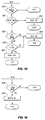
- FIGURES 8-16 are schematic flow charts which serve to illustrate the manner in which the microprocessor is programmed to operate the system of FIGURE 1. Referring now to the drawings and in particular to FIGURE 1, a pasta cooking system in accordance with the present invention is indicated generally by the
reference numeral 10. Thesystem 10 is similar to that illustrated and described in the above referenced U. S. Patent 3,958,503. Accordingly, thesystem 10 includes acabinet 12 which supports acooking vat 14 and aholding vat 16. Theholding vat 16 is essentially a deep sink having a drain with a manually operable valve, neither of which is illustrated. Aswivel faucet 18 is provided to be used to wash pasta or add water to theholding vat 16, or to use water as otherwise desired. Abasket lift 20 is provided to raise and lower a large container for bulk pasta during the cooking cycle, or to raise and lower one or more individual serving baskets. All of the above components may be essentially as described and illustrated in the above referenced patent. - The
cooking vat 14 is illustrated in greater detail in FIGURE 2 and is comprised of a deep drawn, single piece, stainless steel unit having opposite front and rear walls 14a and 14b,opposite side walls bottom wall 14e, and is suitably supported in thecabinet 12. A manually operateddrain valve 22 is provided to drain water from the cooking vat into the local sewer system or other waste disposal means throughconduit 24. Anoverflow weir 26 is positioned in the front wall 14a of thevat 14 and is connected through appropriate plumbing 28 to thedrain 24. Theoverflow weir 26 is thus in constant fluid communication with thewaste disposal drain 24. - A
water inlet line 30 is connected to a source of pressure, such as the local water supply, and is connected to both thefaucet 18 and to a solenoid controlledwater fill valve 32 throughlines fill valve 32 is connected through ahose 38 to aspray nozzle 40 mounted in the rear wall 14b of thecooking vat 14. Either hot or cold water may be provided to thefill valve 32. A submersibleelectric heating element 42 is positioned near the bottom of thevat 14 and is connected to the power supply which is operated by a control circuit which will presently be described in detail mounted generally in anenclosure 44 in the lower part of thecabinet 12. - As can best be seen in FIGURE 4, low and high water
level detector probes temperature probe 50 are mounted on asupport block 52 attached to the rear wall 14b of thevat 14. Ashield 54 is suspended from theblock 52 to protect the three probes. In accordance with an important aspect of the invention, the waterlevel detecting probes cooking vat 14, use alternating current to detect the change in resistance when water touches the lower ends of the probes. The lower end of the lowwater level probe 46 is positioned significantly above theelectric heating element 42 and is used to ensure that theelectric element 42 cannot be energized without an adequate supply of water in the cooking vat. The lower end of the high waterlevel detecting probe 48 is positioned just below the level of theweir 26, and is used by the control circuit to establish a normaloperating water level 15 in the cooking vat for both the cooking and reconstituting cycles. - The
water nozzle 40 is disposed just above the level of theweir 26 and has a number of small openings which establish a water flow around the perimeter of the surface of the water during a skim cycle, as will presently be described in greater detail in connection with FIGURE 5, and over the side walls and bottom of the cooking vat to rinse the vat during a drain cycle. The amount of water introduced through thevalve 32 andnozzle 40 is less than the rate at which water is drained through thevalve 22 when opened so that rinsing can occur automatically during a drain cycle as hereafter described. - A microprocessor based controller for the
system 10 is indicated schematically and designated generally by the reference numeral 60 in FIGURE 6. The controller 60 includes a commerciallyavailable microprocessor 62 which may conveniently include both programmable and dynamic memories necessary for storing an operating program, and for using the program to operate thesystem 10 in response to operator inputs through the keyboard. The power supplies for the various components of this system are eliminated for convenience of illustration, but are conventional and well known in the art. - As previously mentioned, the
low level probe 46 andhigh level probe 48 are single conductor rods which are merely suspended in the water. The rods may be of any suitable conductive material so that an alternating electrical potential, transformed from the local utility power supply, can be applied between therods vat 14 so that the resistance of the air or water between the respective probes and the vat wall can be measured. A significant reduction in the measured resistance indicates that water touches at least the lower end of the respective rods. - Thus, an alternating current from a
power supply 64 is coupled throughcapacitor 66,resistor 68 andcapacitor 70 to thehigh level probe 48 and throughcapacitor 72 andresistor 74 to ground, and thus to the wall of thevat 14, which is, of course, grounded. Theresistor 74 and the resistance of the water between theprobe 48 and the vat forms a biasing network for the positive input of theoperational amplifier 76. Theamplifier 76 is biased in the conventional manner by the resistive network illustrated to operate in a switching mode in response to the presence or absence of water touching theprobe 48 so as to provide essentially a digital signal online 78 to themicroprocessor 62. - Similarly, the alternating current power supply is connected to the low
water level probe 46 throughcapacitor 80,resistor 82 and capacitor 84 so that the resistance between theprobe 46 and the wall of the vat is in parallel with resistor 86 and capacitor 87 to form the voltage divider coupled to the input ofoperational amplifier 88. Theoperational amplifier 88 is also biased to operate in the switching mode so as to produce essentially a high/low digital level on input 90 to themicroprocessor 62. - The
temperature probe 50 is a conventional two-wire, temperature sensing probe which is operated by direct current source 91 and is coupled tooperational amplifier 92, all in a conventional manner to produce aninput 94 to themicroprocessor 62. The input switches to indicate when the water temperature transitions through a temperature below boiling, typically about 205°. A variable resistor 96 is provided in the biasing network to adjust this temperature. As will presently be described, themicroprocessor 62 operates theheater 42 in a thermostatic type on/off mode to maintain a desired simmer temperature of about 205°. - The outputs from the control panel illustrated in FIGURE 6 are connected to the
microprocessor 62 as represented collectively bydata bus 101. These outputs are derived from manual actuation of switches which include the ten numeric buttons 1 through 0 for programming the timer, indicated collectively by thereference numeral 103, and mode switches 104-108 which represent boil temperature, on/off, skim, start time and simmer temperature, respectively. A four digitalphanumeric display 110 is controlled by outputs represented bydata bus 120.Indicator lamps - In addition, the microprocessor is coupled to an alarm sound through
line 126, to operate the basket lowering and raising mechanism as represented byline 128, to turn the power the heating coils on and off as represented byline 130 and to turn the water valve on and off as represented byline 132. The microprocessor is permanently programmed to operate the system using the program represented by the flow charts of FIGURES 8-16. - As illustrated in FIGURE 8, when the power is first turned on, the program resets the central processing unit and clears the random access memory as represented by
block 150. Next, the particular software version which is being employed in the system is displayed as represented byblock 152. The program then enters the main loop as represented byblock 154 and proceeds to repeatedly cycle through the subroutines illustrated in FIGURES 9-16, the headings of which are displayed in theblock 154. - Thus, during the "basket lift" subroutine, a timer which provides enough time for the basket lift to completely lower and return is first checked to see if the count is equal zero as indicated by
block 156. If equal zero, the subroutine is exited. If not, a bit representing the basket status is changed as represented byblock 158 and then the basket reverse bit checked as represented byblock 160. If the basket reverse bit is set, the subroutine is exited. If the basket reverse bit is not set, the timer ofblock 156 is loaded with the predetermined count as represented byblock 162, and the reverse bit is cleared as represented byblock 164 before the subroutine is exited. - After exiting the basket lifts subroutine, the keyboard subroutine of FIGURE 10 is entered where first a check is made to determine if any key is actuated to provide input information, as represented by
block 166. If not, the subroutine is exited. If a key is ready, it is first checked to see if it is an on/off key as represented byblock 168. If yes, the program proceeds to carry out the function inblock 169 of turning the system on. If the on/off key is not the active key, it is checked to determine if the computer is off as represented byblock 170. The computer maintains a status which is toggled by the on/off button on the panel. If the computer is off, the subroutine is exited; if on, the boil or simmer keys are checked as represented by block 172. If a boil or simmer key is active, the function is started as represented byblock 169. If not, the computer next checks to see if the water is low as represented byblock 174, and if so, exits the subroutine. If not, a check is made to see if the system is in a cooking mode, and if so, exits the subroutine. If not, a check is made to see if a number key is active, and if so, the number is entered as represented byblock 178 before exiting the subroutine. The numbers are entered in a display register sequentially and displayed. - Next the computer enters the output subroutine for boil-simmer illustrated in FIGURE 11. First, a check is made to see if the status resulting from the on/off switch is off, and if so, the subroutine is exited as represented by
block 180. If the computer system is not in the off status, a check is made to see if the boil mode has been activated as represented byblock 182, and if so, the set boil mode status is achieved atblock 184 before exiting the subroutine. Similarly, if the simmer switch is active, the simmer mode status is set as representedblock 188 before exiting the subroutine. - A subroutine which responds to an input from the
start time button 107 is illustrated in FIGURE 12 where the water level is first checked as represented asblock 190. If the water is low, the subroutine is exited. If not, the computer off switch is checked at 192. If the on/off status is off, the subroutine is exited, and if on, the skim status mode is checked atblock 194. If the skim mode is on, the subroutine is exited, and if off, the cooking mode is checked atblock 196. If the system is cooking, the cook mode is canceled as represented inblock 198 and the subroutine exited. If not already cooking, the basket lift is lowered as represented by block 200 and the cook mode is set on as represented byblock 202, and the cook time is fetched as represented byblock 204 before exiting the subroutine. - Next the display subroutine represented in FIGURE 13 is entered by first checking to see if the water is low as represented by
block 206. If the water is low, the letters "LO" displayed as represented at 208 and the subroutine exited. If not, the skim mode is checked as represented byblock 209 and if in the skim mode, the remaining time on the skim timer is displayed as represented byblock 210 before exiting the subroutine. As a part of the skim mode initiation, a timer is initiated when the skim mode is started so that the water valve will remain open for a predetermined time, for example, two minutes. If not in the skim mode, the cooking mode is checked as represented byblock 211. If in the cooking mode, the time remaining in the cook timer is displayed as represented by 212. If not in the cook mode, the cook time is loaded from the display register as represented atblock 213 before finally exiting the display program. - Upon entering the water subroutine illustrated in FIGURE 14, the skim mode is checked as represented by
block 220 and, if in the skim mode, the subroutine is exited. If not, a check is made to determine if water level is above the low water level. If so, it is checked to see if the noise timer is equal to zero and if not, the subroutine is exited. The noise timer records the number of times the computer has passed through the main program loop. This timer, which counts down, is typically set at 255 and is used to prevent chatter of the water valve. If the noise timer is equal to zero, the water is turned on as represented byblock 226 and the subroutine exited. If the water is above the low level as indicated atblock 222, it is next checked to determine if the water is above the high level atblock 228. If not, the noise timer is again checked atblock 230 to see if it is equal to zero, and if not, the subroutine is exited. If the noise timer is zero, the heat is turned on as represented byblock 232 and the water is turned on as represented byblock 234 before the subroutine is exited. If the water is below the high, which is the normal operating level, the noise timer is set to the original number as represented byblock 230, the heat is turned on as representedblock 232 and the x-fill timer is loaded as represented byblock 234. The purpose of the x-fill timer is keep the water valve on for fifteen seconds after the high water level probe first detects water to ensure that the final water level is above the end of the probe. This prevents unduly rapid cycling of the water valve as the result of evaporation or other water loss. If the count in the x-fill timer is not zero, as represented byblock 236, the subroutine is exited. If the fill timer is zero, the water is turned off atblock 238 and the subroutine exited. - Next the heat subroutine illustrated in FIGURE 15 is entered by first checking to see if the water level is below the low level as indicated by
block 250 and if so, the subroutine is exited. If the water is above the low level, the heat antichatter timer is checked atblock 252. If the count of the timer is not zero, the heat is turned off atblock 254, and the subroutine exited. If the heat timer is zero, the boil mode status is checked atblock 254 and if in the boil mode is set, the heat is turned on as represented byblock 256 and the subroutine exited. If not in the boil mode, a check is made of the signal from the temperature probe to see if the temperature is greater than the simmer point as represented byblock 258, and if the temperature is less than the simmer point, the heat is turned on as represented byblock 256 before exiting the subroutine. If the temperature is greater than the simmer point, the heat is turned off as represented atblock 260 and the subroutine is exited. - Finally, skim subroutine illustrated in FIGURE 16 is entered by first checking to see if the skim mode is set at
block 264 and if not, the subroutine is immediately exited. If the skim mode is set, the water valve is turned on at 266 and the subroutine exited. - In the normal operation of the
system 10, power for thesystem 10 is turned on by a manual switch, not illustrated, to power up the control system including that represented in FIGURE 5. The water valve will be off, the basket lifts up, the power to the heater turned off and the drain valve closed. The random access memory will have been cleared inblock 150 and the software version will be displayed by the display to indicate that power is on, and the computer will then be operating in themain loop 54. - Assume that no water is in the
cooking vat 14. When the on/off switch is pressed, a water low condition will be detected and displayed to the operator as "LO" as a result of the operation of theblocks blocks block 236. - At any time, the operator can select either the
boil temperature button 104 or the simmer temperature button 108 and thecorresponding display light - At any time the operator may put four digits in the
display 110 by pressing the appropriatenumerical buttons 103, the numbers being scrolled from right-to-left in the display as entered. Assuming that pasta is to be cooked, the boil temperature button will normally be pushed to turn the heating element on continuously until the simmer temperature button is subsequently pushed. When theboil temperature button 104 is pushed, theindicator light 112 is illuminated. When it is desired by the operator to start the cooking cycle, thestart time button 107 is pushed, which results in the basket lowering the pasta into the water. As the cooking period progresses, the time remaining is continually displayed to the operator. When the cooking period has expired, the basket lift automatically raises the pasta from the water, and the full time previously entered in the display is again displayed. The operator can then rinse the pasta with cold water from thefaucet 18 and place the pasta in the individual serving baskets for storage in the adjacent vat. Since the cooking time period has been automatically returned to the display register, the operator need only press thetime start button 107 to start another cooking cycle. - When the cooking operation has been completed, the control automatically reverts to the simmer mode. The computer together with the
temperature probe 50 functions in a thermostatic mode to turn the electrical heating element on and off and maintain the temperature of the water at the desired simmer temperature below boiling, typically about 205°. Using the simmer temperature when operating in the standby mode minimizes the creation of starchy froth due to surface agitation caused by boiling. - When it is desired to reconstitute pasta which has previously been cooked, the desired time is set into the display, for example 15 seconds, and the start time button pressed. The basket lift automatically lowers the pasta into the water which may be at the simmer temperature, or boiling as desired, for the period of time entered into the timer. The time set in the timer reappears at the end of each timed cycle so that subsequent reconstituting cycles requires only the pressing of the
start time button 107. - Whenever an operator desires to remove the foam from the top of the cooking vat, the operator need only press the
skim button 106. This results in thewater fill valve 32 being immediately opened so that water is forced through thenozzle 40 onto the surface of the water. It will noted that thenozzle 40 is slightly above the normal operating level of the water 14a which is defined by the lower end of theprobe 48. Since thenozzle 40 has three small apertures arranged generally as illustrated in FIGURE 4, substantially currents are established in the surface of the water as illustrated by the arrows in the schematic diagram of FIGURE 5. As the water level raises and overflows theweir 26 into thedrains 28 and 24, the surface flow currents carry the starchy foam over the weir into the drain. It has been found to be very important that theweir 26 to have a substantial horizontal width so that a generally uniform layer of water will cascade over the full width of the weir. Otherwise, the foam, which can be quite stiff, tends to bridge between the two sides of the opening, preventing effective removal from the vat. Similarly, it is important for the height for the opening in the vat above the weir to be sufficient to permit the foam to flow freely into the drain without contacting the upper side of the opening and thereby to prevent effective skimming. - The water is introduced during the skimming cycle for a predetermined time period, typically about two minutes, without attention from the operator. After that time period, the
water valve 32 is automatically closed. Thus, the entire skimming cycle can be accomplished at any time by the operator merely pushing the skim button. It is customary to perform the skimming function while the unit is in the simmer temperature mode. The skim cycle thus removes the starchy foam and prolongs the time during which a given vat of water can be used for cooking and/or reconstitution without being discarded through thedrain 22. This not only conserves electrical energy required to reheat cold water used to refill the vat, but also minimizes down time of the unit during critical periods of operation. - When it is desired to drain the vat, the operator need only open the
drain valve 22. This can be done at any time without danger of harming the system due to the low level detector. When thevalve 22 is open, as soon as the water drops below the high level probe, thevalve 32 is immediately turned on to spray water from thenozzle 40 as water continues to drain from the vat. This is due to the fact that the water drains through thedrain valve 22 at a much greater rate than water can be introduced through thenozzle 40. As a result, the spray from thenozzle 40 immediately sets up currents along the side walls of thevat 14 as the water level lowers to rinse the side walls, and finally the bottom wall with considerable efficiency due to the fact that the sprayed water spreads around the side walls to reasonably cover the bottom wall. It will be noted that as the water level falls below the low level probe, theheating element 42 is automatically disabled so that it is protected as the water falls below the heating element. - When the opportunity presents itself, the drain cycle can be terminated by merely closing the manually operated
drain valve 22, at which time water again fills thevat 40 as previously described because the fill valve remains open. - Thus from the above detailed description of preferred embodiments of the invention, it will be appreciated that an improved system for cooking pasta has been described which substantially reduces the manual labor required in filling, operating, and cleaning the unit, which makes the unit available for use for longer periods of time, and which reduces the consumption of energy, yet which is economical to manufacture.
- Although preferred embodiments of the invention have been described in detail, it is to be understood that changes, substitutions, and alterations can be made therein without departing from the spirit and scope of the invention as defined by the appended claims.
Claims (13)
- A system for preparing pasta comprising:
a cooking vat for holding a supply of water having a drain including a value for draining water from the vat and an overflow weir defining a maximum water level in the vat at which point water flows from the vat by gravity into a waste drain,
heating means for heating water in the vat,
means for adding water to the vat from a supply of water under pressure including an electrically operated fill valve,
high level detecting means for detecting a normal high water level which is below the level of the overflow drain, and
control means responsive to the high level detecting means for operating the fill valve in response to the high level detecting means to add water to the vat whenever the high level detecting means indicates that water is below the normal high water level, whereby the vat can be automatically filled and the water maintained at levels between the high water level and the maximum overflow level during pasta preparation. - The system of Claim 1 wherein the control means further includes means for selectively opening the fill valve without regard to the high level detecting means during a skim cycle to add water to the vat until water overflows through the overflow drain to remove starchy foam from the surface of the water.
- The system of Claim 1 or 2 wherein the drain valve, when open, drains water from the vat at a substantially greater rate than water is added to the vat through the fill valve, and the fill valve remains open during a drain cycle to rinse the vat and then refill the vat when the drain valve is closed at the end of the drain cycle.
- The system of Claim 2 or 3 further comprising:
means for introducing water to the vat in a flow pattern which creates surface currents tending to carry starchy foam on the surface of the water over the weir during the skim cycle. - The system of Claim 3 or 4 further comprising:
means for introducing water to the vat in a flow pattern which tends to rinse the walls of the vat as water is drained from the vat during the drain cycle. - The system of Claim 1, 2, 3 or 4, wherein:
the heating means is an electrical heating element disposed in the lower portion of the vat and immersed in water when the vat is filled with water, and further comprising
low water level detection means for detecting a low water level above the heating means and substantially below the normal water level and wherein:
the control means is responsive to low water level detection means for disabling the heating element when the water level is below the low water level. - The system of Claim 1, 2, 3, 4, 5 or 6, wherein:
the cooking vat is electrically conductive;
the detecting means comprises a single conductive element positioned to become immersed in the water when the water reaches the normal high water level and positioned adjacent a wall of the vat, and
the control means includes means for applying an alternating current potential between the conductive element and the wall of the vat and detecting the change in the resistance therebetween when water provides a conductive path between the conductive element and the vat. - A system for preparing pasta comprising:
a cooking vat for holding a supply of water having a drain including a valve for draining water form the vat,
heating means for heating water in the vat,
an overflow weir defining a maximum water level in the vat at which point water flows from the vat by gravity into a waste drain, and
means for selectively adding water to the vat to cause water to overflow the weir any carry contamination floating on the surface over the weir in a surface skimming operation. - The system of Claim 8 wherein the means for selectively adding water to the vat includes manually operable water faucet means disposed above and moveable relative to the surface of the water in the vat.
- The system of Claim 8 or 9 wherein the cooking vat includes front and rear walls and the overflow weir is formed by an opening disposed in the front wall with the weir being the lower edge of the opening, the weir being substantially straight and horizontally disposed and having sufficient horizontal width to pas starchy foam without significant bridging, the opening being sufficiently large to avoid significant interference with the flow of starch from over the weir.
- The system of Claim 10 wherein the means for selectively adding water includes means located near the rear wall of the vat for establishing currents in the surface of the water which facilitates the flow of foam from the surface of the water over the weir.
- A system for preparing pasta comprising:
a cooking vat for holding a supply of water having a drain including a valve for draining water from the vat and an overflow weir defining a maximum water level in the vat at which point water flows over the weir by gravity into a waste drain,
electrical healing means disposed near the bottom of the vat for heating water in the vat,
electrically operated basket lift means for lowering and raising a food product into and out of water in the cooking vat,
means for adding water to the vat from a supply of water under pressure including an electrically operated fill valve,
high level detecting means for detecting a normal high water level which is below the level of the overflow drain,
low level detecting means for detecting a low water level which is above the electrical healing means,
temperature sensing means for detecting when the temperature of the water in the vat is at a simmer temperature below boiling temperature, and
control means responsive to the high level detecting means, the low level detecting means, and the temperature detecting means and including manual input means for selecting an "on" mode, a boil mode, a simmer mode, a skim mode, and a cook mode for a selected period of time, and for
automatically opening the fill valve whenever the systems is in the "on" mode and the water level in the vat is below the normal high water level to attempt to maintain the water at the normal high water level,
opening the fill valve when in the skim mode to add water to the vat and overflow the weir,
turning the heating means on continuously during the boil mode unless the water level is below the low level detecting means,
maintaining the temperature of the water at the simmer temperature during the simmer mode unless the water level is below the low level detecting means, and
timing the duration of the cook mode in response to a manual start time input. - The system of Claim 12 further comprising basket lift means responsive to the control means for automatically lowering a basket containing pasta into the water at the start of a cooking mode and raising the basket from the water at the completion of the cook mode as determined by the timer.
Applications Claiming Priority (2)
| Application Number | Priority Date | Filing Date | Title |
|---|---|---|---|
| US07/702,773 US5313876A (en) | 1991-05-17 | 1991-05-17 | Spaghetti cooking system |
| US702773 | 1991-05-17 |
Publications (2)
| Publication Number | Publication Date |
|---|---|
| EP0513817A2 true EP0513817A2 (en) | 1992-11-19 |
| EP0513817A3 EP0513817A3 (en) | 1993-01-20 |
Family
ID=24822534
Family Applications (1)
| Application Number | Title | Priority Date | Filing Date |
|---|---|---|---|
| EP19920108237 Withdrawn EP0513817A3 (en) | 1991-05-17 | 1992-05-15 | Spaghetti cooking system |
Country Status (4)
| Country | Link |
|---|---|
| US (1) | US5313876A (en) |
| EP (1) | EP0513817A3 (en) |
| JP (1) | JP3234635B2 (en) |
| CA (1) | CA2068845A1 (en) |
Cited By (11)
| Publication number | Priority date | Publication date | Assignee | Title |
|---|---|---|---|---|
| EP0649622A1 (en) * | 1993-10-21 | 1995-04-26 | Hobart Corporation | Screen box for a pasta cooker |
| EP0649623A3 (en) * | 1993-10-21 | 1995-09-27 | Hobart Corp | Pasta cooker. |
| EP1096863A4 (en) * | 1998-07-15 | 2002-03-06 | Joseph Barravecchio | Method and apparatus for rethermalizing pre-cooked food portions |
| EP1919335A4 (en) * | 2005-08-08 | 2010-08-25 | R P Inv S Inc | COOKING DEVICE FOR FROZEN FOODS |
| ITVR20100029A1 (en) * | 2010-02-17 | 2011-08-18 | A & Jp S R L | COOKING AND MOBILE KITCHEN EQUIPMENT EQUIPPED WITH THIS DEVICE. |
| ITVR20100028A1 (en) * | 2010-02-17 | 2011-08-18 | A & Jp S R L | COOKING AND MOBILE KITCHEN EQUIPMENT EQUIPPED WITH THIS DEVICE. |
| US8186265B2 (en) | 2005-08-08 | 2012-05-29 | Ron's Enterprises, Inc. | Device to efficiently cook food |
| US8850965B2 (en) | 2005-08-08 | 2014-10-07 | Ronald M. Popeil | Device to efficiently cook food |
| CN107853979A (en) * | 2017-12-04 | 2018-03-30 | 苏州诺浩众创信息科技研发有限公司 | A kind of intelligent electric cooker with function of washing rice |
| CN110960077A (en) * | 2018-09-30 | 2020-04-07 | 佛山市顺德区美的电热电器制造有限公司 | Cooking appliance and control method thereof |
| US11382450B2 (en) * | 2018-06-18 | 2022-07-12 | Electrolux Professional S.P.A. | Pasta cooking appliance |
Families Citing this family (37)
| Publication number | Priority date | Publication date | Assignee | Title |
|---|---|---|---|---|
| US5574822A (en) * | 1993-03-19 | 1996-11-12 | Bradford White Corporation | Compact electric water heater |
| US5445062A (en) * | 1993-05-21 | 1995-08-29 | Polster; Louis S. | Cooker/rethermalizer |
| US5918344A (en) * | 1996-07-12 | 1999-07-06 | Shop Vac Corporation | Self-evacuating vacuum cleaner |
| USD409440S (en) * | 1997-03-25 | 1999-05-11 | Henny Penny Corporation | Fryer tray carrier |
| US5937741A (en) * | 1997-12-17 | 1999-08-17 | Manger; William M. | Automatic pasta preparer |
| US5942269A (en) * | 1997-12-19 | 1999-08-24 | Henny Penny Corporation | Method for manipulating cooking medium during cooking operations |
| USD412642S (en) | 1998-03-25 | 1999-08-10 | Henny Penny Corporation | Fryer tray carrier with cross-braced support |
| US5974955A (en) * | 1998-03-25 | 1999-11-02 | Henny Penny Corporation | Lifting lid assembly for fryer |
| USD414649S (en) | 1998-03-25 | 1999-10-05 | Henny Penny Corporation | Fryer transfer cart |
| US6085640A (en) * | 1999-11-01 | 2000-07-11 | Henny Penny Corporation | Carrier for deep fat fryer |
| US6182305B1 (en) * | 1999-03-30 | 2001-02-06 | Kohler Co. | Cooking sink with cutting board |
| US6407469B1 (en) * | 1999-11-30 | 2002-06-18 | Balboa Instruments, Inc. | Controller system for pool and/or spa |
| JP2002081573A (en) * | 2000-09-07 | 2002-03-22 | Paloma Ind Ltd | Valve opening and closing device for flyer |
| JP4272804B2 (en) * | 2000-09-19 | 2009-06-03 | パロマ工業株式会社 | Flyer |
| USD462567S1 (en) | 2001-08-28 | 2002-09-10 | Henny Penny Corporation | Automatic basket lifting fryer |
| CA2461120A1 (en) * | 2003-03-14 | 2004-09-14 | The Vollrath Company, L.L.C. | Food server fluid level control |
| US6953913B1 (en) * | 2004-07-26 | 2005-10-11 | Premier Restaurant Equipment Co. | Hot pan |
| US7604001B2 (en) * | 2005-06-03 | 2009-10-20 | Craghead John W | Kitchen cooktop system |
| US7853130B2 (en) * | 2006-03-29 | 2010-12-14 | Premark Feg L.L.C. | Steam generator for a steam cooker having an automated draining process |
| CA2649712C (en) | 2006-04-18 | 2013-01-22 | Oy Halton Group Ltd. | Low flow exhaust system |
| TW200815711A (en) * | 2006-09-18 | 2008-04-01 | Seven Universe Ind Co Ltd | Gas stove |
| CA2568468C (en) * | 2006-11-17 | 2015-01-20 | Paul M. Kehoe | Electric cooker |
| US9289096B2 (en) * | 2007-11-16 | 2016-03-22 | Wolfedale Engineering Limited | Temperature control device and method |
| WO2009062281A1 (en) | 2007-11-16 | 2009-05-22 | Wolfedale Engineering Limited | Temperature control apparatus for a barbeque grill |
| US9320388B2 (en) * | 2009-11-15 | 2016-04-26 | Legupro Ab | Liquid movement and control within a container for food preparation |
| US8616121B1 (en) * | 2010-03-22 | 2013-12-31 | Paul Hansalik | Cooktop drain |
| US20130323386A1 (en) * | 2012-06-01 | 2013-12-05 | Andrew Luketic | Automated circulating reservoir thaw device |
| WO2014036669A1 (en) * | 2012-09-07 | 2014-03-13 | Zhang Bens | Pressurization- or decompression-based infrared detection water tank |
| CA2870397A1 (en) * | 2013-11-06 | 2015-05-06 | Lucien Fauteux | Automated self-contained cooking assembly |
| CN107847069B (en) * | 2015-07-07 | 2020-11-06 | 皇家飞利浦有限公司 | Pressure cooking device |
| CN108236396B (en) * | 2016-12-23 | 2024-01-16 | 广东美的生活电器制造有限公司 | Cooking machine pulping method |
| CN108236403B (en) * | 2016-12-23 | 2024-01-16 | 广东美的生活电器制造有限公司 | Cooking machine pulping method |
| AU2018300993B2 (en) * | 2017-07-12 | 2024-06-13 | Home Tech Innovation, Inc. | Food cartridges and carriers for use in a cooking device |
| US10976097B2 (en) | 2017-09-15 | 2021-04-13 | Home Tech Innovation, Inc. | Apparatus and methods for at least semi-autonomous meal storage and cooking |
| IT201800004840A1 (en) * | 2018-04-24 | 2019-10-24 | COOKING PROCEDURE | |
| US12082736B2 (en) | 2019-02-14 | 2024-09-10 | Techmagic Inc. | Automatic dish serving system, a restaurant, an automatic system for a restaurant, an automatic dish serving method, a program and a storage medium |
| JP7255250B2 (en) * | 2019-03-13 | 2023-04-11 | 三菱電機株式会社 | Storage hot water heater |
Family Cites Families (15)
| Publication number | Priority date | Publication date | Assignee | Title |
|---|---|---|---|---|
| US2287396A (en) * | 1941-05-09 | 1942-06-23 | Joe Lowe Corp | Fat leveling system |
| US2533930A (en) * | 1948-01-12 | 1950-12-12 | Herman H Harr | Beverage preparing and dispensing apparatus |
| US3107601A (en) * | 1958-09-02 | 1963-10-22 | Richard L Longmire | Filtration and recirculation system for deep fat cooking apparatus |
| US2978975A (en) * | 1958-11-10 | 1961-04-11 | Rossi Peter | Apparatus for cooking farinaceous materials |
| US3383951A (en) * | 1965-06-08 | 1968-05-21 | Manitowoc Co | Multiple variable torque converter apparatus |
| US3788302A (en) * | 1971-10-29 | 1974-01-29 | William Underwood Co | Maintaining the water level in baking beans |
| GB1470524A (en) * | 1973-08-09 | 1977-04-14 | Still Sons Ltd W | Water boilers |
| US3958503A (en) * | 1974-05-03 | 1976-05-25 | The Frymaster Corporation | Spaghetti cooking system |
| US4450757A (en) * | 1982-09-20 | 1984-05-29 | Angelo Po Grandi Impianti S.P.A. | Automatic machine for cooking soup-paste, rice, pot herbs or other food-stuffs in water |
| US4491146A (en) * | 1982-09-22 | 1985-01-01 | Groen Division/Dover Corporation | Liquid level control |
| US4508026A (en) * | 1983-07-25 | 1985-04-02 | Anetsberger Brothers, Inc. | Basket moving mechanism for deep fat fryer |
| EP0164415A1 (en) * | 1983-12-09 | 1985-12-18 | United Midwest International Corporation | Swimming pool cleaning system and apparatus |
| IT1184698B (en) * | 1984-04-12 | 1987-10-28 | Giovanni Barbieri | FOOD COOKING APPLIANCE |
| FR2596250B3 (en) * | 1986-03-27 | 1988-02-26 | Aldeguer Rene | DEVICE FOR COOKING PASTA |
| US5103801A (en) * | 1990-03-08 | 1992-04-14 | Keating Of Chicago, Inc. | Automatic cooking vessel |
-
1991
- 1991-05-17 US US07/702,773 patent/US5313876A/en not_active Expired - Fee Related
-
1992
- 1992-05-15 CA CA002068845A patent/CA2068845A1/en not_active Abandoned
- 1992-05-15 EP EP19920108237 patent/EP0513817A3/en not_active Withdrawn
- 1992-05-18 JP JP16818692A patent/JP3234635B2/en not_active Expired - Fee Related
Cited By (15)
| Publication number | Priority date | Publication date | Assignee | Title |
|---|---|---|---|---|
| EP0649622A1 (en) * | 1993-10-21 | 1995-04-26 | Hobart Corporation | Screen box for a pasta cooker |
| US5452648A (en) * | 1993-10-21 | 1995-09-26 | Hobart Corporation | Screen box for a pasta cooker |
| EP0649623A3 (en) * | 1993-10-21 | 1995-09-27 | Hobart Corp | Pasta cooker. |
| EP1096863A4 (en) * | 1998-07-15 | 2002-03-06 | Joseph Barravecchio | Method and apparatus for rethermalizing pre-cooked food portions |
| US8707857B2 (en) | 2005-08-08 | 2014-04-29 | Ronald M. Popeil | Cooking device to deep fat fry foods |
| US8186265B2 (en) | 2005-08-08 | 2012-05-29 | Ron's Enterprises, Inc. | Device to efficiently cook food |
| US8309151B2 (en) | 2005-08-08 | 2012-11-13 | Ron's Enterprises, Inc. | Device to efficiently cook food |
| EP1919335A4 (en) * | 2005-08-08 | 2010-08-25 | R P Inv S Inc | COOKING DEVICE FOR FROZEN FOODS |
| US8850965B2 (en) | 2005-08-08 | 2014-10-07 | Ronald M. Popeil | Device to efficiently cook food |
| ITVR20100029A1 (en) * | 2010-02-17 | 2011-08-18 | A & Jp S R L | COOKING AND MOBILE KITCHEN EQUIPMENT EQUIPPED WITH THIS DEVICE. |
| ITVR20100028A1 (en) * | 2010-02-17 | 2011-08-18 | A & Jp S R L | COOKING AND MOBILE KITCHEN EQUIPMENT EQUIPPED WITH THIS DEVICE. |
| CN107853979A (en) * | 2017-12-04 | 2018-03-30 | 苏州诺浩众创信息科技研发有限公司 | A kind of intelligent electric cooker with function of washing rice |
| US11382450B2 (en) * | 2018-06-18 | 2022-07-12 | Electrolux Professional S.P.A. | Pasta cooking appliance |
| CN110960077A (en) * | 2018-09-30 | 2020-04-07 | 佛山市顺德区美的电热电器制造有限公司 | Cooking appliance and control method thereof |
| CN110960077B (en) * | 2018-09-30 | 2021-07-20 | 佛山市顺德区美的电热电器制造有限公司 | Cooking appliance and control method thereof |
Also Published As
| Publication number | Publication date |
|---|---|
| US5313876A (en) | 1994-05-24 |
| JP3234635B2 (en) | 2001-12-04 |
| EP0513817A3 (en) | 1993-01-20 |
| JPH06153839A (en) | 1994-06-03 |
| CA2068845A1 (en) | 1992-11-18 |
Similar Documents
| Publication | Publication Date | Title |
|---|---|---|
| US5313876A (en) | Spaghetti cooking system | |
| JPS63150034A (en) | Cooking apparatus | |
| US3790391A (en) | Apparatus for steam pressure cooking of food | |
| US4214514A (en) | Cooker for individual portions of particulate foodstuff | |
| AU676607B2 (en) | Pasta cooker | |
| US6063421A (en) | Method and apparatus for rethermalizing pre-cooked food portions | |
| JP3937857B2 (en) | Rice washing machine | |
| JP3536356B2 (en) | Drainage end detection device for rice washing rice cooker | |
| JP3163804B2 (en) | Operation display of rice washing rice cooker | |
| JP3536336B2 (en) | Water control of rice washing rice cooker | |
| KR940003677B1 (en) | Automatic cooking device and method | |
| JP3271311B2 (en) | Rice cooker | |
| JP2000350660A (en) | Operation control device in rice washing rice cooker | |
| JPS5836350Y2 (en) | boiling noodle bowl | |
| JPS5854015Y2 (en) | boiling noodle bowl | |
| JP3491293B2 (en) | Operation control device in rice washing rice cooker | |
| JP2903928B2 (en) | Rice cooker and preheating control method thereof | |
| JP3525598B2 (en) | Washing equipment for rice washing rice cooker | |
| KR20040058605A (en) | Multi-fryer | |
| JP3321973B2 (en) | Rice washing rice cooker operation control device | |
| JPH0638874A (en) | Automatic rice washing and rice cooking device | |
| JP3528320B2 (en) | Reservation operation device in rice washing rice cooker | |
| JPH0994159A (en) | Automatic rice washing and cooking apparatus | |
| JPH02283333A (en) | Full-automatic rice-washing and rice-cooking jar | |
| JPH064052B2 (en) | Rice cooker |
Legal Events
| Date | Code | Title | Description |
|---|---|---|---|
| PUAI | Public reference made under article 153(3) epc to a published international application that has entered the european phase |
Free format text: ORIGINAL CODE: 0009012 |
|
| AK | Designated contracting states |
Kind code of ref document: A2 Designated state(s): AT BE CH DE DK ES FR GB GR IT LI LU MC NL PT SE |
|
| PUAL | Search report despatched |
Free format text: ORIGINAL CODE: 0009013 |
|
| AK | Designated contracting states |
Kind code of ref document: A3 Designated state(s): AT BE CH DE DK ES FR GB GR IT LI LU MC NL PT SE |
|
| STAA | Information on the status of an ep patent application or granted ep patent |
Free format text: STATUS: THE APPLICATION IS DEEMED TO BE WITHDRAWN |
|
| 18D | Application deemed to be withdrawn |
Effective date: 19930721 |