EP0513471A2 - Surgical instrument - Google Patents
Surgical instrument Download PDFInfo
- Publication number
- EP0513471A2 EP0513471A2 EP92100368A EP92100368A EP0513471A2 EP 0513471 A2 EP0513471 A2 EP 0513471A2 EP 92100368 A EP92100368 A EP 92100368A EP 92100368 A EP92100368 A EP 92100368A EP 0513471 A2 EP0513471 A2 EP 0513471A2
- Authority
- EP
- European Patent Office
- Prior art keywords
- surgical instrument
- pliers
- recess
- instrument according
- guide
- Prior art date
- Legal status (The legal status is an assumption and is not a legal conclusion. Google has not performed a legal analysis and makes no representation as to the accuracy of the status listed.)
- Withdrawn
Links
Images


Classifications
-
- A—HUMAN NECESSITIES
- A61—MEDICAL OR VETERINARY SCIENCE; HYGIENE
- A61B—DIAGNOSIS; SURGERY; IDENTIFICATION
- A61B17/00—Surgical instruments, devices or methods, e.g. tourniquets
- A61B17/28—Surgical forceps
- A61B17/29—Forceps for use in minimally invasive surgery
-
- A—HUMAN NECESSITIES
- A61—MEDICAL OR VETERINARY SCIENCE; HYGIENE
- A61B—DIAGNOSIS; SURGERY; IDENTIFICATION
- A61B17/00—Surgical instruments, devices or methods, e.g. tourniquets
- A61B17/28—Surgical forceps
- A61B17/2812—Surgical forceps with a single pivotal connection
- A61B17/2833—Locking means
-
- A—HUMAN NECESSITIES
- A61—MEDICAL OR VETERINARY SCIENCE; HYGIENE
- A61B—DIAGNOSIS; SURGERY; IDENTIFICATION
- A61B17/00—Surgical instruments, devices or methods, e.g. tourniquets
- A61B17/28—Surgical forceps
- A61B17/29—Forceps for use in minimally invasive surgery
- A61B17/2909—Handles
-
- B—PERFORMING OPERATIONS; TRANSPORTING
- B25—HAND TOOLS; PORTABLE POWER-DRIVEN TOOLS; MANIPULATORS
- B25B—TOOLS OR BENCH DEVICES NOT OTHERWISE PROVIDED FOR, FOR FASTENING, CONNECTING, DISENGAGING OR HOLDING
- B25B7/00—Pliers; Other hand-held gripping tools with jaws on pivoted limbs; Details applicable generally to pivoted-limb hand tools
- B25B7/14—Locking means
- B25B7/16—Locking means combined with means for tightening the operating arms of jaws
-
- A—HUMAN NECESSITIES
- A61—MEDICAL OR VETERINARY SCIENCE; HYGIENE
- A61B—DIAGNOSIS; SURGERY; IDENTIFICATION
- A61B17/00—Surgical instruments, devices or methods, e.g. tourniquets
- A61B17/32—Surgical cutting instruments
- A61B17/320016—Endoscopic cutting instruments, e.g. arthroscopes, resectoscopes
-
- A—HUMAN NECESSITIES
- A61—MEDICAL OR VETERINARY SCIENCE; HYGIENE
- A61B—DIAGNOSIS; SURGERY; IDENTIFICATION
- A61B17/00—Surgical instruments, devices or methods, e.g. tourniquets
- A61B2017/0046—Surgical instruments, devices or methods, e.g. tourniquets with a releasable handle; with handle and operating part separable
-
- A—HUMAN NECESSITIES
- A61—MEDICAL OR VETERINARY SCIENCE; HYGIENE
- A61B—DIAGNOSIS; SURGERY; IDENTIFICATION
- A61B17/00—Surgical instruments, devices or methods, e.g. tourniquets
- A61B17/28—Surgical forceps
- A61B17/2812—Surgical forceps with a single pivotal connection
- A61B17/2833—Locking means
- A61B2017/2837—Locking means with a locking ratchet
-
- A—HUMAN NECESSITIES
- A61—MEDICAL OR VETERINARY SCIENCE; HYGIENE
- A61B—DIAGNOSIS; SURGERY; IDENTIFICATION
- A61B17/00—Surgical instruments, devices or methods, e.g. tourniquets
- A61B17/28—Surgical forceps
- A61B17/29—Forceps for use in minimally invasive surgery
- A61B17/2909—Handles
- A61B2017/2912—Handles transmission of forces to actuating rod or piston
- A61B2017/2919—Handles transmission of forces to actuating rod or piston details of linkages or pivot points
- A61B2017/292—Handles transmission of forces to actuating rod or piston details of linkages or pivot points connection of actuating rod to handle, e.g. ball end in recess
-
- A—HUMAN NECESSITIES
- A61—MEDICAL OR VETERINARY SCIENCE; HYGIENE
- A61B—DIAGNOSIS; SURGERY; IDENTIFICATION
- A61B17/00—Surgical instruments, devices or methods, e.g. tourniquets
- A61B17/28—Surgical forceps
- A61B17/29—Forceps for use in minimally invasive surgery
- A61B2017/2926—Details of heads or jaws
- A61B2017/2932—Transmission of forces to jaw members
- A61B2017/2933—Transmission of forces to jaw members camming or guiding means
- A61B2017/2934—Transmission of forces to jaw members camming or guiding means arcuate shaped guiding means
-
- A—HUMAN NECESSITIES
- A61—MEDICAL OR VETERINARY SCIENCE; HYGIENE
- A61B—DIAGNOSIS; SURGERY; IDENTIFICATION
- A61B17/00—Surgical instruments, devices or methods, e.g. tourniquets
- A61B17/28—Surgical forceps
- A61B17/29—Forceps for use in minimally invasive surgery
- A61B2017/2926—Details of heads or jaws
- A61B2017/2932—Transmission of forces to jaw members
- A61B2017/2939—Details of linkages or pivot points
- A61B2017/294—Connection of actuating rod to jaw, e.g. releasable
-
- A—HUMAN NECESSITIES
- A61—MEDICAL OR VETERINARY SCIENCE; HYGIENE
- A61B—DIAGNOSIS; SURGERY; IDENTIFICATION
- A61B90/00—Instruments, implements or accessories specially adapted for surgery or diagnosis and not covered by any of the groups A61B1/00 - A61B50/00, e.g. for luxation treatment or for protecting wound edges
- A61B90/03—Automatic limiting or abutting means, e.g. for safety
- A61B2090/031—Automatic limiting or abutting means, e.g. for safety torque limiting
-
- A—HUMAN NECESSITIES
- A61—MEDICAL OR VETERINARY SCIENCE; HYGIENE
- A61B—DIAGNOSIS; SURGERY; IDENTIFICATION
- A61B90/00—Instruments, implements or accessories specially adapted for surgery or diagnosis and not covered by any of the groups A61B1/00 - A61B50/00, e.g. for luxation treatment or for protecting wound edges
- A61B90/08—Accessories or related features not otherwise provided for
- A61B2090/0813—Accessories designed for easy sterilising, i.e. re-usable
Landscapes
- Health & Medical Sciences (AREA)
- Life Sciences & Earth Sciences (AREA)
- Surgery (AREA)
- Engineering & Computer Science (AREA)
- Medical Informatics (AREA)
- Nuclear Medicine, Radiotherapy & Molecular Imaging (AREA)
- Biomedical Technology (AREA)
- Heart & Thoracic Surgery (AREA)
- Ophthalmology & Optometry (AREA)
- Molecular Biology (AREA)
- Animal Behavior & Ethology (AREA)
- General Health & Medical Sciences (AREA)
- Public Health (AREA)
- Veterinary Medicine (AREA)
- Mechanical Engineering (AREA)
- Surgical Instruments (AREA)
Abstract
Description
Die Erfindung betrifft ein chirurgisches Instrument insbesondere für die Endoskopie mit einem schließbaren Maul aus Maulteilen, wie Zangen- oder Scherenschenkel, welche an einem Zugelement festgelegt sind, wobei zumindest ein Maulteil eine Drehachse mit dem Zugelement bildet und um diese Drehachse drehbar angeordnet ist und wobei das Zugelement ein Schaftrohr zumindest teilweise durchzieht.The invention relates to a surgical instrument, in particular for endoscopy, with a closable mouth made of jaw parts, such as pliers or scissor legs, which are attached to a tension element, at least one jaw part forming an axis of rotation with the tension element and being arranged rotatably about this axis of rotation, and wherein Pulling element at least partially runs through a shaft tube.
Derartige chirurgische Instrumente sind als Zangen, Scheren, Klemmen od. dgl. in vielfältigen Ausführungsformen bekannt und dienen den unterschiedlichsten Zwecken. In der Regel bestehen sie aus zwei Maulteilen, welche relativ zueinander bewegt werden, wobei dann ein Klemmen, Schneiden oder Scheren erfolgt.Surgical instruments of this type are known as pliers, scissors, clamps or the like in various embodiments and serve a wide variety of purposes. As a rule, they consist of two jaw parts which are moved relative to one another, with clamping, cutting or shearing then taking place.
Nur beispielhaft wird auf die DE-OS 39 21 935 verwiesen, aus welcher eine Endoskopiezange bekannt ist. Die Zangenschenkel sind dort über einen Drehbolzen miteinander verbunden. Andererseits dieses Drehbolzens ist an die Zangenschenkel ein Zugseil, eine Zustange od. dgl. angekoppelt. Mit dem Zugseil ist ein Führungselement verbunden, welches zumindest einen Führungskanal aufweist, in welchen ein Hebelansatz eingreift, welcher einem Zangenschenkel jenseits des Drehbolzens bzw. eines Drehpunktes angeformt ist. Wird an diesem Führungselement gezogen, so schließt oder öffnet sich das durch die Zangenschenkel gebildete Maul.Reference is made only to DE-OS 39 21 935 by way of example, from which an endoscopic forceps is known. The pliers legs are connected to each other by a pivot pin. On the other hand, this pivot pin is coupled to the pliers legs with a pull rope, a rod or the like. With the pull rope is a guide element connected, which has at least one guide channel, in which a lever shoulder engages, which is formed on a pliers leg beyond the pivot pin or a fulcrum. If this guide element is pulled, the mouth formed by the pliers legs closes or opens.
Nachteilig bei diesen bisher bekannten Zangen ist vor allem, daß sie nach Gebrauch nur unter erheblichen Mühen auseinander genommen, gereinigt und sterilisiert werden können. Auch der Zusammenbau erfordert wiederum einen hohen Zeitaufwand bzw. ist mit einem Berühren der an sich steril zu haltenden Teile verbunden.A disadvantage of these previously known pliers is, above all, that after use they can only be taken apart, cleaned and sterilized with considerable effort. The assembly also requires a lot of time or involves touching the parts that are to be kept sterile.
Ferner läßt bei vielen chirurgischen Instrumenten diese Art die Bewegungsmechanik sehr zu wünschen übrig, vor allem, wenn es um die Kraftübertragung auf die Maulteile geht.Furthermore, with many surgical instruments, this type of movement mechanics leaves much to be desired, especially when it comes to the transmission of force to the jaw parts.
Weiterhin sind aus den deutschen Gebrauchsmustern 87 12 328.2 und 88 14 560.3 Endoskopiezangen bekannt, bei denen die Maulteile mit dem Zugelement eine Drehachse bilden. Die Führung dieser Maulteile erfolgt in entsprechenden Wanddurchbrechungen des Schaftrohres, was allerdings sehr ungenau ist. Auch die Kraftübertragung zum Öffnen bzw. Schließen des Maules läßt sehr zu wünschen übrig. Ferner muß zur Reinigung die obere Hülse von der Spirale abgedreht werden.Furthermore, from
Der vorliegenden Erfindung liegt die Aufgabe zugrunde, eine möglichst perfekte Bewegungsmechanik bei optimaler Kraftübertragung auf die Maulteile zu schaffen, wobei gleichzeitig ein außerordentlich leichtes und wenig zeitaufwendiges Auseinandernehmen des chirurgischen Instrumentes möglich ist.The object of the present invention is to create a movement mechanism that is as perfect as possible with optimal power transmission to the jaw parts, while at the same time an extraordinarily light and less time-consuming disassembly of the surgical instrument is possible.
Zur Lösung dieser Aufgabe führt, daß zumindest einem Maulteil von außen her eine Ausnehmung eingeformt ist, deren Mittelpunkt um die Drehachse am Zugelement dreht, wobei die Ausnehmung in Gebrauchslage ein in der Wand des Schaftrohres vorgesehenes Ringstück zumindest teilweise umfängt und das Maulteil bei seiner Schließ- oder Öffnungsbewegung um dieses Ringstück dreht.The solution to this problem is that at least one jaw part is formed from the outside, the center of which rotates about the axis of rotation on the tension element, the recess in the position of use at least partially encompassing a ring piece provided in the wall of the shaft tube and the jaw part rotating about this ring piece during its closing or opening movement.
Das Zusammenspiel zwischen dem Ringstück im Schaftrohr und der Ausnehmung ist von besonderer Bedeutung. Sobald das Zugelement sich in dem Schaftrohr bewegt, wird diese axiale Bewegung durch ein Gleiten der Ausnehmung um das Ringstück in eine Drehbewegung des bzw. der Maulteile umgesetzt. Somit gleiten zumindest Teile der Ausnehmung immer an den Wänden des Ringstückes entlang.The interaction between the ring piece in the shaft tube and the recess is of particular importance. As soon as the pulling element moves in the shaft tube, this axial movement is converted into a rotary movement of the jaw part or parts by sliding the recess around the ring piece. Thus at least parts of the recess always slide along the walls of the ring piece.
Damit nicht nur eine einseitige Bewegung des Maulteiles möglich ist, sollte die Ausnehmung etwa halbkreisförmig ausgebildet sein. Bei einem Zug am Zugelement wird hierdurch das Maulteil geschlossen, während in entgegengesetzter Richtung das Maulteil geöffnet wird.So that not only one-sided movement of the jaw part is possible, the recess should be approximately semicircular. When the pulling element is pulled, the jaw part is closed, while the jaw part is opened in the opposite direction.
Damit ein gutes Zusammenspiel zwischen Ringstück und Ausnehmung gewährleistet ist, sollte der Radius der Ausnehmung nur geringfügig größer sein, als der Radius des Ringstückes. In Gebrauchslage liegen somit sowohl der Mittelpunkt der Ausnehmung als auch der Mittelpunkt des Ringstückes nahe beieinander, so daß möglichst viel Flächenberührung zwischen Ringstück und Ausnehmung vorhanden ist. Hierdurch wird die Führung des Maulteiles verbessert.In order to ensure a good interaction between the ring piece and the recess, the radius of the recess should only be slightly larger than the radius of the ring piece. In the position of use, both the center of the recess and the center of the ring piece are close together, so that there is as much surface contact as possible between the ring piece and the recess. This improves the guidance of the jaw part.
In einem Ausführungsbeispiel der Erfindung kann ein Maulteil feststehend ausgebildet sein, während sich das andere Maulteil relativ zu diesem feststehenden Maulteil bewegt. Beide sind über den oben genannten Gelenkbolzen miteinander verbunden. Hier genügt es selbstverständlich, wenn in dem bewegbaren Maulteil die Ausnehmung vorgesehen ist und wenn das Schaftrohr nur einen Durchbruch oder eine Nut und nur ein ensprechendes Ringstück zum Eingleiten in die Ausnehmung besitzt. Allerdings sollte dann das feststehende Maulteil eine gesonderte Ausnehmung besitzen, in welche der Führungsschenkel des bewegbaren Maulteiles verschwinden kann.In one exemplary embodiment of the invention, one jaw part can be designed to be stationary, while the other jaw part moves relative to this stationary jaw part. Both are connected to each other via the hinge pin mentioned above. It is of course sufficient here if the recess is provided in the movable jaw part and if the shaft tube has only one opening or one groove and only has a corresponding ring piece for sliding into the recess. However, the fixed jaw part should then have a separate recess into which the guide leg of the movable jaw part can disappear.
In den bevorzugten Ausführungsbeispielen sind allerdings beide Maulteile bewegbar und somit indentisch ausgebildet, wobei dann auch zwei entsprechende Durchbrüche oder Nuten und zwei entsprechende Ringstücke in der Schaftwand angeordnet sind.In the preferred exemplary embodiments, however, both jaw parts can be moved and are therefore designed identically, with two corresponding openings or grooves and two corresponding ring pieces then being arranged in the shaft wall.
Zur Befestigung der beiden Maulteile genügt dann eine Gabel mit zwei Gabelschenkeln an dem Zugelement, wobei die Maulteile über einen entsprechenden Stift mit den Gabelschenkeln verbunden sind. Bei einem Herausnehmen des Zugelementes zusammen mit den Maulteilen können infolge der Ausbildung der Ausnehmung die Führungsschenkel in den Bereich zwischen die Gabelschenkel einfahren, so daß sie sich beim Herausnehmen des Zugelementes nicht störend auswirken. Somit kann dieses Zugelement zusammen mit den Maulteilen getrennt vom Schaft sterilisiert und gereinigt werden. Gleichzeitig ist auf einfache Weise auch eine Reinigung des Schaftinneren möglich.A fork with two fork legs on the pulling element is then sufficient to fasten the two jaw parts, the jaw parts being connected to the fork legs via a corresponding pin. When the pulling element is removed together with the jaw parts, the guide legs can move into the area between the fork legs as a result of the design of the recess, so that they do not have a disruptive effect when the pulling element is removed. This pulling element can be sterilized and cleaned together with the jaw parts separately from the shaft. At the same time, cleaning the inside of the shaft is also possible in a simple manner.
Der Zusammenbau erfolgt wiederum auf einfache Weise, indem die beiden Maulteile etwa waagerecht angeordnet werden. Hierbei verschwinden die Führungsschenkel wieder zwischen den Gabelschenkeln und das Zugelement kann zusammen mit den Maulteilen in das Schaftrohr eingesetzt werden. Beim Eingleiten der Ringstücke in die Ausnehmung werden dann wiederum die Führungsschenkel aus ihrer versteckten Lage geschwenkt und gleiten in den Durchbruch ein, wobei die Maulteile um den Stift bzw. Gelenkbolzen drehen.The assembly is again carried out in a simple manner by arranging the two jaw parts approximately horizontally. Here, the guide legs disappear again between the fork legs and the pulling element can be inserted into the shaft tube together with the jaw parts. When the ring pieces slide into the recess, the guide legs are then swiveled out of their hidden position and slide into the opening, the jaw parts rotating around the pin or pivot pin.
Das Ringstück kann im übrigen auch eine andere Ausgestaltung aufweisen. Beispielsweise kann hier ein Drehbolzen in eine sackschlitzartige Ausnehmung eingesetzt sein.The ring piece can also have a different configuration. For example, a Pivot pin can be inserted into a slot-like recess.
Damit beim Einsetzen der Maulteile in das Schaftrohr gleich eine Zentrierung erfolgt, so daß die Führungsschenkel die Durchbrüche finden, ist erfindungsgemäß eine Führungsklammer 31 vorgesehen, welche dem Schaftrohr aufgesetzt werden kann. Diese Führungsklammer besteht in den vorliegendem Ausführungsbeispiel aus zwei offenen Bögen, welche über Raststreifen miteinander verbunden sind. Zwischen den Bögen werden die Maulteile aufgenommen. Die Raststreifen besitzen wiederum Rastnasen, deren Lage axial mit den Führungsschenkeln übereinstimmt. Diese Rastnasen klipsen dann in die Durchbrüche ein, so daß von dem Schaftinneren her die Führungsschenkel in jedem Fall den Durchbruch finden. Dies ist eine bevorzugte Ausführungsform der Erfindung.So that a centering takes place immediately when the jaw parts are inserted into the shaft tube so that the guide legs find the openings, a
Eine andere Möglichkeit der Zentrierung bzw. der Erleichterung des Einsetzens der Maulteile in das Schaftrohr besteht darin, daß an dem Zugelement ein Kolbenstück vorhanden ist, in welches zumindest eine Führungsnut eingeformt ist. Diese Führungsnut spielt dann beim Einsetzen des Kolbenstückes in das Schaftrohr mit einer entsprechenden Führungsnase in dem Schaftrohr zusammen. Hierdurch wird gleichzeitig eine Verdrehsicherung gewährleistet.Another possibility of centering or facilitating the insertion of the jaw parts into the shaft tube is that a piston piece is present on the tension element, into which at least one guide groove is formed. This guide groove then interacts with a corresponding guide lug in the shaft tube when the piston piece is inserted into the shaft tube. This also ensures an anti-rotation device.
Insgesamt ist das chirurgische Instrument außerordentlich einfach aufgebaut und leicht zu bedienen. Es läßt eine hohe Kraftübertragung auf die Maulteile zu, so daß die Schneidwirkung verbessert ist. Hervorzuheben ist vor allem das leichte Auseinandernehmen. Hierzu braucht lediglich das Zugelement von einem entsprechenden Zangen- bzw. Scherengriff od. dgl. gelöst zu werden.Overall, the surgical instrument is extremely simple and easy to use. It allows a high power transmission to the jaw parts, so that the cutting effect is improved. The easy disassembly is particularly noteworthy. For this purpose, only the pulling element needs to be released from a corresponding pliers or scissor handle or the like.
Diesem Zweck dient vor allem auch eine weitere Ausgestaltung der Erfindung. Zur Bewegung der beiden Maulteile sind entsprechende Zangenschenkel vorgesehen, welche durch die menschliche Hand geöffnet und geschlossen werden können. An dem einen Zangenschenkel ist das Schaftrohr, meist in einer Halterung, festgelegt, während das Zugelement in der Regel mit dem anderen Zangenschenkel verbunden ist. Im vorliegenden Ausführungsbeispiel weist das Zugelement eine Mitnehmerkugel auf, welche in Gebrauchslage in einer Kugelaufnahme in einem Hals dieses Zangenschenkels sitzt. Beide Zangenschenkel drehen dann um einen gemeinsamen Drehpunkt.A further embodiment of the invention also serves this purpose. Corresponding pliers legs are provided for moving the two jaw parts, which can be opened and closed by the human hand. The shaft tube, usually in a holder, is fixed on one pliers leg, while the tension element is usually connected to the other pliers leg. In the present exemplary embodiment, the pulling element has a driver ball which, in the position of use, is seated in a ball receptacle in a neck of this pliers leg. Both pliers legs then rotate around a common pivot point.
Damit nun das Zugelement auf einfache Weise von seinem Zangenschenkel gelöst werden kann, andererseits aber nicht bei einer normalen Betätigung des chirurgischen Instrumentes aus seiner Halterung gleitet, sollte eine Riegeleinrichtung vorgesehen sein, welche die Bewegung der beiden Zangenschenkel zueinander begrenzt. Die Begrenzung der Bewegung bewirkt, daß bei normaler Betätigung der Zangen die Mitnehmerkugel in jeder Endlage in der Kugelaufnahme verbleibt, daß aber beim Lösen dieser Riegeleinrichtung der eine Zangenschenkel soweit geschwenkt werden kann, daß die Mitnehmerkugel einfach aus der Kugelaufnahme gleitet und dann das Zugelement zusammen mit den Maulteilen aus dem Schaftrohr gezogen werden kann.So that the pulling element can now be detached from its pliers leg in a simple manner, but on the other hand does not slide out of its holder during normal operation of the surgical instrument, a locking device should be provided which limits the movement of the two pliers legs relative to one another. The limitation of the movement means that with normal operation of the pliers, the driver ball remains in the ball seat in every end position, but when the locking device is released, one of the pliers legs can be pivoted so far that the driver ball simply slides out of the ball holder and then the pulling element together with the jaw parts can be pulled out of the shaft tube.
In einer bevorzugten Ausführungsform weist diese Riegeleinrichtung im wesentlichen einen Rundbogen auf, der ebenfalls um den Drehpunkt der beiden Zangenschenkel dreht. Zu seiner Aufnahme ist in den einen Zangenschenkel eine Führungsrinne eingeformt, in welcher der Rundbogen gleitet. In der einen Endlage, in welcher die Bewegung der beiden Zangenschenkel zueinander begrenzt werden soll, ragt der Rundbogen mit einem Anschlagbolzen über eine Anschlagfläche hinaus, so daß der eine Zangenschenkel nur bis zu diesem Anschlagbolzen bewegt werden kann. Wird dagegen der Rundbogen in seiner Lage verändert, so verschwindet dieser Anschlagbolzen in dem Zangenschenkel. D.h., der Zangenschenkel kann bis zur Anschlagfläche geschwenkt werden, wobei in dieser Endlage die Mitnehmerkugel aus der Kugelaufnahme gleiten kann.In a preferred embodiment, this locking device essentially has a round arch, which also rotates around the pivot point of the two pliers legs. To accommodate it, a guide groove is formed in one of the pliers legs, in which the round arch slides. In the one end position, in which the movement of the two pliers limbs to one another is to be limited, the round arch projects with a stop bolt beyond a stop surface, so that the one pliers limb can only be moved up to this stop bolt. However, if the The position of the round arch changes, this stop bolt disappears in the pliers leg. Ie, the pliers leg can be swiveled up to the stop surface, whereby the driver ball can slide out of the ball seat in this end position.
Bevorzugt soll der Rundbogen in seiner Endlage, in der er mit einem Anschlagbolzen über die Anschlagfläche hinaussteht, lösbar festgelegt sein. Dies geschieht auf einfache Weise, indem der Rundbogen in dieser Endlage eine im Zangenschenkel vorgesehene Rastnase hintergreift. Durch einen einfachen Druck auf eine Lasche od. dgl. an dem Rundbogen kann der Rundbogen aus dieser Rastnasenlagerung herausgeschoben werden, so daß er dann frei ist und um den Drehpunkt drehen kann.The arch should preferably be releasably fixed in its end position, in which it projects with a stop bolt beyond the stop surface. This is done in a simple manner by the round arch engaging behind a locking lug provided in the pliers limb in this end position. By simply pressing a tab or the like on the round arch, the round arch can be pushed out of this latching bearing so that it is then free and can rotate about the pivot point.
Die vorliegende Erfindung befaßt sich auch mit einer weiteren Ausgestaltung der Zangenschenkel bzw. deren Festlegung zueinander, die bevorzugt bei dem vorliegenden chirurgischen Instrument Anwendung finden soll. Allerdings soll die vorliegende Erfindung nicht auf diese ausschließliche Anwendung beschränkt sein, sondern die nachfolgend beschriebene Ausgestaltung einer Sperreinrichtung ist auf viele chirurgische Instrumente übertragbar, die mit Zangen- bzw. Scherengriffen arbeiten.The present invention also relates to a further configuration of the forceps legs and their fixing to one another, which is preferably to be used in the present surgical instrument. However, the present invention is not intended to be restricted to this exclusive application, but the configuration of a locking device described below can be transferred to many surgical instruments which work with forceps or scissor handles.
Der erfinderische Gedanke bezieht sich vor allem auf die Möglichkeit, die Zangenschenkel in einem bestimmten Verhältnis zueinander festzulegen.The inventive idea relates above all to the possibility of fixing the pliers legs in a certain relationship to one another.
Hierfür sind Sperreinrichtungen bekannt, wobei beispielsweise zwei Sperrleisten an jedem Schenkel befestigt sind und sich über- bzw. untergreifen, wobei jeweiligen Zähne miteinander in Eingriff stehen. Nachteilig ist dabei, daß zum Lösen der Sperreinrichtung eine zweite Hand notwendig ist.Locking devices are known for this purpose, two locking bars, for example, being attached to each leg and overlapping or engaging, the respective teeth being in engagement with one another. The disadvantage here is that a second hand is required to release the locking device.
Eine andere Sperreinrichtung besteht aus einer Sperrleiste, welche einerseits gelenkig mit dem einen Zangenschenkel verbunden ist und andererseits von einer Feder gegen einen Rastzahn an dem anderen Zangenschenkel gedrückt wird. Wird davon ausgegangen, daß der Benutzer die Zange bzw. Schere mit Daumen und Zeigefinger bedient, so kann diese Sperreinrichtung nur mit der anderen Hand gelöst werden.Another locking device consists of a locking bar, which on the one hand is articulated to one pliers leg and on the other hand is pressed by a spring against a locking tooth on the other pliers leg. If it is assumed that the user operates the pliers or scissors with his thumb and forefinger, this locking device can only be released with the other hand.
Andere Sperreinrichtungen sind entweder schwer zu bedienen oder aber sehr kompliziert aufgebaut.Other locking devices are either difficult to use or have a very complicated structure.
Die vorliegende weitere Ausgestaltung der Erfindung entwickelt einen Zangen- bzw. Scherengriff, bei welchem die Sperreinrichtung sehr einfach aufgebaut und vor allem sehr leicht mit nur einer Hand zu betätigen ist und zwar mit der Hand, die auch den Zangen- bzw. Scherengriff selbst betätigt.The present further embodiment of the invention develops a pliers or scissor handle, in which the locking device is very simple and, above all, very easy to operate with only one hand and with the hand that also operates the plier or scissor handle itself.
Diesem Zweck dient, daß an die Sperrleiste ein Hebelschenkel ggfs. mit einer Fingermulde anschließt.For this purpose, a lever arm connects to the locking bar, if necessary, with a finger recess.
Das Drehen der Sperrleiste, welche die Sperrzähne außer Eingriff mit dem Einrastzahn bringt, kann mittels eines Fingers derjenigen Bedienhand bewirkt werden, welche auch den Zangen- bzw. Scherengriff hält. Meist wird dies mittels dem Mittelfinger, Ringfinger oder kleinen Finger geschehen.The turning of the locking bar, which brings the locking teeth out of engagement with the latching tooth, can be effected by means of a finger of the operating hand which also holds the pliers or scissor handle. This is usually done using the middle finger, ring finger or little finger.
Bevorzugt soll die Sperrleiste unter dem Druck eines Kraftspeichers stehen, wobei der Druck bewirkt, daß die Sperrleiste in Eingriff mit dem Einrastzahn bleibt. Dies bedeutet, daß vom Bediener zum Lösen der Sperreinrichtung lediglich eine Bewegung eines Fingers in eine Richtung durchgeführt werden muß. Die Einrastbewegung wird dann von dem Kraftspeicher übernommen.The locking bar should preferably be under the pressure of an energy accumulator, the pressure causing the locking bar to remain in engagement with the latching tooth. This means that the operator only has to move one finger in one direction to release the locking device. The latching movement is then taken over by the energy accumulator.
Die Sperrleiste kann dem Zangenschenkel mit dem Einrastzahn anliegen oder ihn umgreifen. Bevorzugt wird jedoch in den Zangenschenkel ein Schlitz eingeformt, den die Sperrleiste durchgreift. Hierdurch stört die Sperrleiste die normale Zangen- bzw. Scherengrifftätigkeit am wenigsten. Ferner wird hierdurch die Sperrleiste gesicherter geführt.The locking bar can rest against the pliers leg with the snap-in tooth or can encompass it. However, preference is given to the Pliers legs a slot is formed, which passes through the locking bar. As a result, the locking bar disturbs the normal pliers or scissor handle activity the least. Furthermore, the locking bar is guided more securely.
Greift die Sperrleiste den Zangenschenkel von außen her an, so ist dort dem Zangenschenkel ein zusätzlicher Einrastzahn angeformt. Durchgreift die Sperrleiste allerdings in dem bevorzugten Ausführungsbeispiel den Zangenschenkel, so genügt es, wenn dort eine Schlitzkante keilförmig zu einem Einrastzahn geformt ist.If the locking bar attacks the pliers leg from the outside, an additional latching tooth is formed there on the pliers leg. However, in the preferred embodiment, if the locking bar extends through the pliers limb, it is sufficient if a slot edge is wedge-shaped there to form a snap-in tooth.
Gedacht ist auch an eine klammerförmige Aufnahme für die Sperrleiste an dem anderen Zangenschenkel, in welche die Sperrleiste eingreift.Also contemplated is a bracket-shaped receptacle for the locking bar on the other pliers leg, in which the locking bar engages.
Für die Lagerung der Sperrleiste an dem anderen Zangenschenkel ist an einen einfachen Gelenkstift gedacht, um den herum die Sperrleiste drehen kann. Damit ein günstiger Angriff des als Federstreifen ausgebildeten Kraftspeichers erfolgt, soll die Anlenkung mittels einer hakenförmigen Anformung erfolgen, welche zwischen sich und der eigentlichen Sperrleiste eine Eingriffsmulde ausbildet, in die der Kraftspeicher eingreifen und gegen den Haken drücken kann. Dabei ist in einem bevorzugten Ausführungsbeispiel der Kraftspeicher als ein einfacher Federstreifen ausgebildet, der an einer Innenfläche des Zangenschenkels festliegt. Gegen diesen Federstreifen stützt sich dann eine Stirnfläche des Hakens oberhalb des Gelenkstiftes ab, so daß die Sperrleiste unter einer Vorspannung in eine Richtung zum Einrastzahn hin steht.A simple hinge pin, around which the locking bar can rotate, is intended for mounting the locking bar on the other pliers leg. In order that the energy accumulator designed as a spring strip is attacked favorably, the articulation should take place by means of a hook-shaped projection which forms an engagement trough between itself and the actual locking bar, into which the energy accumulator can engage and press against the hook. In a preferred exemplary embodiment, the energy accumulator is designed as a simple spring strip which is fixed on an inner surface of the pliers leg. An end face of the hook is then supported against this spring strip above the hinge pin, so that the locking bar is under a prestress in one direction towards the latching tooth.
Weitere Vorteile, Merkmale und Einzelheiten der Erfindung ergeben sich aus der nachfolgenden Beschreibung bevorzugter Ausführungsbeispiele sowie anhand der Zeichnung; diese zeigt in
- Fig. 1 einen Längsschnitt durch ein erfindungsmäßes chirurgisches Instrument;
- Fig. 2 eine Explosionsdarstellung von Teilen des chirurgischen Instrumentes gem. Fig. 1, teilweise gebrochen dargestellt ;
- Fig. 3 einen Längsschnitt durch einen Teilbereich des chirgischen Instrumentes gem. Fig. 1 in einer weiteren Gebrauchslage;
- Fig. 4 einen Längsschnitt durch einen Teilbereich des chirurgischen Instrumentes gem. Fig 1 in zwei unterschiedlichen Gebrauchslagen;
- Fig. 5 einen teilweise dargestellten Längsschnitt durch ein weiteres Ausführungsbeispiel des chirurgischen Instrumentes gem. Fig. 1;
- Fig. 6 einen teilweise gebrochen dargestellten Ausschnitt aus Fig. 5 um 90 Grad gedreht;
- Fig. 7 einen teilweise dargestellten Längsschnitt durch ein weiteres Ausführungsbeispiel eines chirurgischen Instrumentes gem. Fig. 1;
- Fig. 8 einen Längsschnitt durch einen Teilbereich eines weiteren Ausführungsbeispiels eines chirurgischen Instrumentes;
- Fig. 9 einen teilweise dargestellten Längsschnitt durch ein weiteres Ausführungsbeispiel eines chirurgischen
Instruments ähnlich Figur 7; - Fig. 10 einen Längsschnitt durch einen Teilbereich eines weiteren Ausführungsbeispiels eines chirurgischen Instrumentes;
- Fig. 11 eine Draufsicht auf einen Teil des chirurgischen Instrumentes gemäß Figur 10;
- Fig. 12 eine Draufsicht auf ein Maulteil des chirurgischen Instrumentes geäß Figur 10;
- Fig. 13 eine Draufsicht auf einen erfindungsgemässen Zangen- bzw. Scherengriff in Öffnungslage;
- Fig. 14 Querschnitte durch verschiedene Ausführungsformen von Rastelementen;
- Fig. 15 eine Draufsicht auf ein weiteres Ausführungsbeispiel eines erfindungsgemäßen Zangen- bzw. Scherengriffes in Öffnungslage;
- Fig. 16 eine Draufsicht auf das Ausführungsbeispiel des erfindungsgemäßen Zangen- bzw.
Scherengriffs gemäß Figur 15 in einer weiteren Gebrauchslage; - Fig. 17 eine vergrößert dargestellte Draufsicht auf einen Teilbereich des erfindungsgemäßen Zangen- bzw. Scherengriffes entsprechend Figur 13;
- Fig. 18 eine vergrößert dargestellte Draufsicht auf den Teilbereich des Zangen- bzw. Scherengriffs entsprechend Figur 17 in einer weiteren Gebrauchslage;
- Fig. 19 eine Draufsicht auf ein weiteres Ausführungsbeispiel eines erfindungsgemäßen Zangen- bzw. Scherengriffs in Öffnungslage;
- Fig. 20 eine Draufsicht auf den Zangen- bzw.
Scherengriff gemäß Figur 19, jedoch in Schließlage; - Fig. 21 und 22 Draufsichten auf ein weiteres Ausführungsbeispiel eines erfindungsgemäßen Zangen- bzw. Scherengriffs entsprechend den Fig. 19
und 20.
- 1 shows a longitudinal section through a surgical instrument according to the invention.
- Fig. 2 is an exploded view of parts of the surgical instrument acc. Fig. 1, shown partially broken;
- Fig. 3 shows a longitudinal section through a portion of the surgical instrument acc. 1 in a further position of use;
- Fig. 4 shows a longitudinal section through a portion of the surgical instrument. 1 in two different positions of use;
- Fig. 5 is a partially shown longitudinal section through a further embodiment of the surgical instrument acc. Fig. 1;
- FIG. 6 shows a section from FIG. 5, shown partially broken, rotated by 90 degrees;
- Fig. 7 is a partially shown longitudinal section through another embodiment of a surgical instrument acc. Fig. 1;
- 8 shows a longitudinal section through a partial region of a further exemplary embodiment of a surgical instrument;
- 9 shows a partially illustrated longitudinal section through a further exemplary embodiment of a surgical instrument similar to FIG. 7;
- 10 shows a longitudinal section through a partial region of a further exemplary embodiment of a surgical instrument;
- 11 shows a plan view of a part of the surgical instrument according to FIG. 10;
- 12 shows a plan view of a jaw part of the surgical instrument according to FIG. 10;
- 13 shows a plan view of a pliers or scissor handle according to the invention in the open position;
- 14 shows cross sections through different embodiments of locking elements;
- 15 shows a plan view of a further exemplary embodiment of a pliers or scissor handle according to the invention in the open position;
- FIG. 16 shows a plan view of the exemplary embodiment of the pliers or scissor handle according to FIG. 15 in a further position of use;
- FIG. 17 shows an enlarged plan view of a partial area of the pliers or scissor handle according to FIG. 13;
- 18 shows an enlarged plan view of the partial area of the pliers or scissor handle corresponding to FIG. 17 in a further position of use;
- 19 shows a plan view of a further exemplary embodiment of a pliers or scissor handle according to the invention in the open position;
- 20 shows a plan view of the pliers or scissor handle according to FIG. 19, but in the closed position;
- 21 and 22 are top views of a further exemplary embodiment of a pliers or scissor handle according to the invention corresponding to FIGS. 19 and 20.
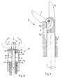
Ein erfindungsgemäßes chirurgisches Instrument R, wie beispielsweise eine Zange oder Schere für die Endoskopie, weist ein Schaftrohr 1 auf, in welchem eine Zugstange 2 geführt ist. Im vorliegenden Ausführungsbeispiel ist die Zugstange 2 im wesentlichen aus einer Stange 3 sowie einem Kolbenstück 4 zusammengesetzt, wobei das Kolbenstück 4 einen größeren Durchmesser aufweist als die Stange 3. Einends ist an die Stange 3 über ein Anschlußstück 5 eine Mitnehmerkugel 6 angeformt, während andernends in dem Kolbenstück 4 zwei bewegbare Maulteile 7 und 8 lagern. An Stelle der Maulteile 7 und 8 können hier auch Scherenteile, Zangenschenkel oder ähnliche Instrumententeile festgelegt sein.A surgical instrument R according to the invention, such as pliers or scissors for endoscopy, has a
Die Mitnehmerkugel 6 dient zum Anschluß an einen Scheren- oder Zangengriff in bekannter Ausführung, wobei dann die Mitnehmerkugel 6 in einer entsprechenden Ausnehmung des Scherenteiles sitzt und das Anschlußstück 5 einen Schlitz durchgreift. Von diesem Scherengriff ist ferner ein weiteres Führungsstück 9 gezeigt, welches ebenfalls von der Stange 3 durchsetzt ist.The
Sowohl für das Führungsstück 9 bzw. das gesamte Scherenteil als auch für die Zugstange 2 sind vielfältige Ausführungsformen denkbar und bekannt und sollen von der vorliegenden Erfindung umfaßt werden. Beispielsweise kann die Stange 3 auch durch ein flexibles Zugseil ersetzt werden. Ferner ist in Fig. 5 erkennbar, daß zur Rückführung der Zugstange 2 Federn 10 in dem Schachtrohr 1 angeordnet sein können. Hier sind, wie gesagt, vielfältige Ausführungsformen bekannt.Various embodiments are conceivable and known both for the
Wesentlich im Rahmen der vorliegenden Erfindung ist dagegen die Ausgestaltung der Maulteile 7 und 8, deren Anordnung und Verbindung an dem Kolbenstück 4 sowie der vordere Bereich des Schachtrohres 1 zum Führen dieser Maulteile 7 bzw. 8. Jedes Maulteil 7, 8 weist eine Schneid- oder Klemmkante 11 auf, welche generell als Arbeitskante bezeichnet werden kann. Von der Spitze 12 des Maulteils 7, 8 schließt dann eine gebogenen Rückwand 13 an, in welche eine halbkreisförmige Ausnehmung 14 eingeformt ist. Durch diese halbkreisförmige Ausnehmung 14 wird ein Führungsschenkel 15 ausgebildet, der später näher beschrieben ist.What is essential in the context of the present invention, however, is the configuration of the
Beide Maulteile 7 und 8 sind im Bereich ihrer Führungsschenkel 15 bzw. neben den halbkreisförmigen Ausnehmungen 14 über einen Stift 16 mit dem Kolbenstück 4 verbunden, wobei hierzu in dem Kolbenstück 4, wie in Fig.2 gezeigt, eine Gabel aus zwei Gabelschenkeln 17 und 18 vorgesehen ist. Diese beiden Schenkel 17 und 18 nehmen zwischen sich die Maulteile 7 und 8 auf, so daß dann lediglich der Stift 16 durch die entsprechenden Gelenkbohrungen 19, 20 bzw. 21 der Schenkel 17, 18 bzw. der Maulteile 7 und 8 eingesetzt werden muß.Both
In Fig. 2 ist ferner eine Rückansicht eines Maulteiles 7/8 gezeigt, welches nur als Ausführungsbeispiel gedacht sein soll. Hierbei ist das Maulteil 7/8 im wesentlichen halbschalenförmig ausgebildet, so daß sich eine teilkalottenartige Rückwand 13 ausbildet. Daran schließt sich dann die Ausnehmung 14 an, welche jedoch zum Führungsschenkel 15 hin lediglich im Bereich eines Anschlußstreifens 22 vorgesehen ist.FIG. 2 also shows a rear view of a
In den Figuren 1 und 2 ist ferner erkennbar, daß sich im Schaft 1 beidseits Durchbrüche 23 befinden, welche der später erwähnten Aufnahme der Führungsschenkel 15 dienen. Zu einem Schaftrohrrandrand 24 hin sind die Durchbrüche 23 von einem, querschnittlich gesehen, halbkreisförmigen Ringstück 25 begrenzt, das in der entsprechenden Form aus der Wand 26 des Schaftrohres 1 herausgeformt ist. Dieses Ringstück 25 bildet zum Schaftrohrrand 24 hin, eine trichterförmige Einzugswand 27, während es den Durchbruch 23 ebenfalls trichterförmig erweitert, durch eine entsprechende Gleitkante 28 freigibt.In Figures 1 and 2 it can also be seen that there are
Die Funktionsweise der vorliegenden Erfindung ist folgende:
Zu Reinigungszwecken bzw. zum Desinfizieren wird die Mitnehmerkugel 6 oder eine ähnliche Halterung von dem entsprechenden Griffteil gelöst und die Zugstange 2 zu- sammen mit den Maulteilen 7 und 8 aus dem Anschlußstück 9 bzw. dem Schaftrohr 1 herausgezogen. Nunmehr kann sowohl das Schaftrohr in seinem Inneren wie auch die Zugstange 2 mit den Maulteilen 7 und 8 intensiv und in allen Bereichen gereinigt werden.The operation of the present invention is as follows:
For cleaning purposes or for disinfecting, the
Zum Zusammenbau wird die Zugstange 2 wieder in das Schaftrohr 1 bzw. das Führungsstück 9 eingesetzt, wobei sich die Maulteile 7 und 8 in der in Fig. 1 gezeigten Gebrauchslage befinden. Dabei verschwinden die Führungsschenkel 15 beider Maulteile 7 und 8 zwischen den Gabelschenkeln 17 und 18, so daß sie zwischen den Ringstücken 25 durchgreifen können.For assembly, the
Sobald sich die Führungsschenkel 15 beider Maulteile 7 und 8 innerhalb der lichten Weite der Ringstücke 25 befin- den, schlägt die Rückwand 13 jedes Maulteiles 7 bzw. 8 an dem Schaftrohrrand 24 an, so daß die Maulteile 7 und 8 in Schließrichtung z bewegt werden. Hierbei öffnet sich die Ausnehmung 14 jedes Maulteiles 7 und 8 zu dem entsprechendem Ringstück 25 hin, wobei die Einzugswand 27 in die Ausnehmung 14 eingleitet, während der Führungsschenkel 15 der Gleitkante 28 aufgleitet und in den Durchbruch 23 einfährt. Diese unterschiedlichen Gebrauchslagen sind in den Figuren 3 und 4 stufenweise dargestellt. In Fig.4 unten ist erkennbar, wie das Ringstück 25 in die halbkreisförmige Ausnehmung 14 eingreift. Diese umschließt das Ringstück 25 zumindest teilweise.As soon as the
In einer einer weiteren Gebrauchslage gem. Fig. 3 sind die Führungsschenkel 15 bereits weitgehend in die Durchbrüche 23 eingefahren und die Maulteile 7 und 8 auf dem Wege zu einer Schließstellung. Diese Schließstellung ist letztendlich in Fig. 4 oben für ein Maulteil 7 dargestellt. Dabei sitzt der Führungsschenkel 15 in dem Durchbruch 23, während das Ringstück 25 in der Ausnehmung 14 auf das Maulteil 7 drückt. Hierdurch ergibt sich eine sehr günstige Kraftverteilung.In a further position of use acc. Fig. 3, the
In einem weiteren Ausführungsbeispiel R1 der Erfindung gem. Fig. 7 ist dem entsprechenden Kolbenstück 4a ein Maulteil 8 a einstückig angeformt. Dieses feststehende Maulteil 8a ist über einen Gelenkbolzen 29 mit dem bewegbaren Maulteil 7 verbunden, welches, wie oben beschrieben, ausgestaltet ist. Damit das festehende Maulteil 8a zumindest den Führungsschenkel 15 des Maulteiles 7 aufnehmen kann, ist in dem feststehenden Maulteil 8a eine Ausnehmung 30 ausgebildet.In a further embodiment R1 of the invention acc. Fig. 7 is a
In diesem Ausführungsbeispiel braucht in der Wand 26 des Schaftrohres 1a nur ein Durchbruch 23 für einen Führungsschenkel 15 vorgesehen sein. Deshalb ist hier auch zum Schaftrohrrand 24 hin nur ein Ringstück 25a ausgebildet.In this exemplary embodiment, only one
Beim Herausziehen des Kolbenstückes 4a verschwindet der Führungsschenkel 15 in der Ausnehmung 30 und bildet so kein Hindernis für die Herausnahme. Beim Einsetzen dagegen schlägt das Ringstück 25a in der Ausnehmung 14 an, so daß die Ausnehmung 14 dieses Ringstück 25a umfaßt, wobei der Führungsschenkel 15 in den Durchbruch 23 einfährt und das Maulteil 7 um den Gelenkbolzen 29 gedreht wird.When the piston piece 4a is pulled out, the
In der Praxis hat sich gezeigt, daß insbesondere bei Verwendung von flexiblen Zugseilen anstelle von starren Zugstange 2 das Suchen der Durchbrüche 23 Schwierigkeiten macht. Um diesem Nachteil zu begegnen, ist dem Schachtrohr 1 gem. den Figuren 5 unnd 6 eine Führungsklammer 31 aufgesetzt. Diese Führungsklammer 31 bildet durch zwei offene Bögen 32 und 33 einen offenen U-förmigen Raum aus, in welchem sich die Maulteile 7 und 8 bewegen können. Beide Bögen 32 und 33 sind mittels Raststreifen 35 und 36 miteinander verbunden, wobei an jedem Raststreifen 35 und 36 nach innen eine Rastnase 37 angeformt ist, welche in den Durchbruch 23 einrasten kann. Hierdurch wird die Führungsklammer 31 lagefixiert, so daß auch die Maulteile 7 und 8 in den Raum 34 bezüglich des Schaftrohres 1 genau geführt sind. Da sich die Rastnasen 37 ebenso wie die Führungsschenkel 15 außermittig befinden, wird so gewährleistet, daß die Führungsschenkel 15 in die Durchbrüche 23 eingreifen und dabei die Rastnasen 37 aus den Durchbrüchen 23 verdrängen, so daß die Führungsklammer 31 abgenommen werden kann.In practice, it has been found that, in particular when using flexible pulling cables instead of rigid pulling
In dem weiteren Ausführungsbeispiel eines erfindungsgemäßen chirurgischen Instrumentes R2 gemäß Figur 8 ist erkennbar, daß ein entsprechendes Schaftrohr 1b keine Durchbrüche 23 für die entsprechenden Führungsschenkel 15 aufweist. Das Schaftrohr 1b ist somit nach außen hin eine geschlossene Hülse, so daß sich auch in einem Durchbruch kein Schmutz, Gewebereste od. Blut ansammeln kann.In the further exemplary embodiment of a surgical instrument R2 according to the invention according to FIG. 8, it can be seen that a corresponding shaft tube 1b has no
Damit dennoch die Maulteile 7 und 8 mit den Ringstücken 25 in entsprechender Weise zusammenwirken, sind in das Schaftrohr 1b von innen her Nuten 40 eingeformt, in welche die Führungsschenkel 15 eingreifen können. Dabei ist selbstverständlich denkbar, daß die Führungsschenkel 15 wesentlich kürzer als dargestellt ausgebildet sind.So that the
Ferner ist in Figur 8 anstelle der oben beschriebenen Führungsklammer 31 eine andere Zentriermöglichkeit bzw. Führung eines Kolbenstückes 4a vorgesehen, welche eine Führungsklammer 31 entfallen läßt. Das Kolbenstück 4a ist als eine verlängerte Hülse ausgebildet. Wobei ihr beidseits von außen her Führungsnuten 41 eingeformt sind. In diese Führungsnuten 41 greifen Führungsnase 42 ein, welche dem Schaftrohr 1b innen angeformt sind. Diese Führungsnasen 42 bewirken zusammen mit den Führungsnuten 41 eine Zentrierung des Kolbenstückes 4a und damit auch der Maulteile 7 und 8. Ferner bewirken sie eine Verdrehsicherheit.Furthermore, in FIG. 8, instead of the
In der weiteren Ausführungsform R3 eines erfindungsgemäßen chirurgischen Instrumentes gemäß Figur 9 ist lediglich gezeigt, daß auch hier ein Schaftrohr 1c keinen Durchbruch aufweist, wie dieser noch gemäß Figur 7 vorgesehen war. Statt dessen ist auch dort dem Schaftrohr 1c nach dem Ringstück 25a von innen her eine Nut 40a eingeformt, in welche der Führungsschenkel 15 eingleiten kann.In the further embodiment R3 of a surgical instrument according to the invention according to FIG. 9, it is only shown that here, too, a shaft tube 1c has no breakthrough, as was also provided according to FIG. 7. Instead of this, a groove 40a is also formed there from the inside of the shaft tube 1c after the
Die Figuren 10 bis 12 betreffen eine andere Ausgestaltung der Maulteile 7/8 und deren Führung an einem Ringstück 25a. Das Ringstück 25a weist hier zwar auch eine Einzugswand 27 und eine Gleitkante 28 auf, allerdings sind pro Ringstück 25a zwei scheibenförmige Elemente 43 vorgesehen, zwischen denen ein Drehbolzen 44 mit wesentlich geringererem Durchmesser angeordnet ist.Figures 10 to 12 relate to another embodiment of the
Dieser Drehbolzen 44 sitzt in Gebrauchslage in einer Ausnehmung 14a, welche als Sackschlitz ausgebildet ist. Der Grund dieser Ausnehmung 14a ist ebenfalls halbkreisförmig, so daß auch hier ein Mittelpunkt M ausgebildet ist, der in Gebrauchslage in etwa mit einem Mittelpunkt M1 des Drehbolzens 44 übereinstimmt.In the use position, this
Auch die scheibenförmigen Elemente 43 sitzen in Gebrauchslage in entsprechenden Aussparungen 45 der Maulteile 7/8 und drehen in diesen. Hierdurch findet eine gute Abstützung der Maulteile 7/8 statt.The disc-shaped
In Figur 11 ist des weiteren erkennbar, daß in das Schaftrohr 1d eine Dehnungsfuge 46 eingeschnitten ist, welche eventuelle Passungenauigkeiten ausgleicht.In Figure 11 it can also be seen that an
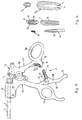
Ein erfindungsgemäßer Zangen- bzw. Scherengriff P für ein chirurgisches Instrument R weist gemäß Figur 13 zwei Zangenschenkel 51 und 52 auf, welche an einem Drehpunkt 53 miteinander gelenkig verbunden sind. Um den Drehpunkt 53 herum erfolgt eine Öffnungs- bzw. Schließbewegung in Richtung des Doppelpfeiles 54. Derartige Zangen- bzw. Scherengriffe finden auch ihren Einsatz bei chirurgischen Instrumenten, wie diese in der Europäischen Patentschrift 0 279 358 gezeigt sind. In der Regel schließt an eine entsprechende Halterung 55 des Zangenschenkels 51 eine eigentliche Arbeitseinrichtung des chirurgischen Instrumentes, insbesondere das Schaftrohr 1, an, welches dann von der Zugstange 2 durchzogen ist, die über die Mitnehmerkugel 6 mit einem Hals 56 des anderen Zangenschenkels 2 verbunden ist.A forceps or scissors handle P according to the invention for a surgical instrument R has, according to FIG. 13, two
Zur Betätigung der Zangenschenkel 51 und 52, d.h., zur Durchführung der Öffnungs- bzw. Schließbewegungen in Richtung des Doppelpfeiles 54 sind im vorliegenden Ausführungsbeispiel Griffösen 57 und 58 jedem Zangeschenkel 51 bzw. 52 angeformt. Anstelle der Griffösen 57 und 58 können auch an dem Zangenschenkeln 51 und 52 beispielsweise einfache Griffrillen od. dgl. vorgesehen sein.To actuate the
Wesentlich ist, daß die Zangenschenkel 51 und 52 durch eine Sperreinrichtung E im Abstand zueinander festgelegt werden können. Diese Sperreinrichtung E weist einen Hebel 60 auf, der mit dem Zangenschenkel 51 über einen Gelenkstift 61 drehbar verbunden ist. Hierzu sind dem Zangenschenkel 51 zwei Laschen 52 angeformt, welche den Hebel 60 klammerartig umgreifen.It is essential that the
Die Sperrleiste 69 ist einer Aufnahme 71 zugeordnet, die sich an dem anderen Zangenschenkel 52 befindet. In diesem Ausführungsbeispiel gemäß Figur 13 besteht die Aufnahme aus zwei Klammerstreifen 72 und 73, welche dem Zangenschenkel 52 bevorzugt einstückig angeformt sind. Inwändig sind den beiden Klammerstreifen 72 und 73 jeweils Rastzähne 74 eingeformt, welche mit entsprechenden Rastzähnen 75 auf der Außenfläche der Sperrleiste 69 zusammenwirken.The locking
Die Funktionsweise des erfindungsgemäßen Zangen- bzw. Scherengriffs ist folgende:The operation of the pliers or scissor handle according to the invention is as follows:
Zur freien Bewegung der beiden Zangenschenkel 51 und 22 wird die Sperreinrichtung E gelöst, indem über den Hebel 60 die Sperrleiste 69 aus dem Eingriffsbereich der Aufnahme 71 geschwenkt wird. Die Rastzähne 74 sind außer Eingriff mit den Rastzähnen 75. Durch den Bediener wird der Hebel 60 in der entsprechenden Stellung gehalten, wobei beispielsweise der kleine Finger des Bedieners in der Fingermulde 70 liegen kann.For free movement of the two
Sollen die Zangenschenkel 51 und 52 in einem bestimmten Verhältnis zueinander festgelegt werden, so bringt der Bediener die Sperrleiste 69 in eine Position, in der diese in die Aufnahme 71 einfahren kann. Dabei rasten die Rastzähne 75 in den Rastzähnen 74 ein. Bei Bedarf kann diese Sperre wieder durch einen entsprechenden Druck auf den Hebelschenkel 78 aufgehoben werden.If the
In Figur 14 ist eine Draufsicht auf und ein Querschnitt durch die Sperrleiste 69 dargestellt. Neben ihr ist im Querschnitt die Aufnahme 71 zu erkennen und vor allem auch die Rastzähne 74. Darüber ist ein Querschnitt durch die Aufnahme 71 dargestellt, wobei vor allem eine ovale Innenform erkennbar ist, welche eine bessere Führung der im Querschnitt ovalen Sperrleiste 69 gewährleistet.FIG. 14 shows a top view of and a cross section through the locking
In einem weiteren Ausführungsbeispiel kann eine Aufnahme 71a auch nur nach einer Aufnahmeöffnung 77 mit wenigen Rastzähnen 74 belegt sein. Der entsprechende Querschnitt ist ebenfalls in Figur 14 darüber dargestellt.In a further exemplary embodiment, a receptacle 71a can also be populated with a few locking
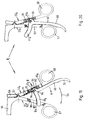
Die Figuren 15 und 16 verdeutlichen, daß die Sperreinrichtung E1 auch umgedreht angeordnet sein kann, d.h., daß sich der Hebel 60 an dem Zangenschenkel 52 und die Aufnahme 71 an dem Zangenschenkel 51 befindet. Auch diese Ausführungsform soll vom Erfindungsgedanken umfaßt sein, da sie mit der in Figur 13 gezeigten Ausführungsform äquivalent ist.Figures 15 and 16 illustrate that the locking device E1 can also be arranged upside down, i.e. that the
In den Figuren 15 bis 18 ist jedoch noch eine besonders bevorzugte Riegeleinrichtung Q dargestellt, welche zum eine gewährleistet, daß bei der Bewegung der Zangenschenkel 51 und 52 die Verbindung der Zugstange 2 an dem Hals 56 erhalten bleibt, daß andererseits aber diese Verbindung auf einfache Weise gelöst werden kann, damit eine Entnahme der Zugstange aus dem Schaftrohr 1 und damit eine Reinigung der entsprechenden Teile sehr leicht möglich ist.In Figures 15 to 18, however, a particularly preferred locking device Q is shown, which on the one hand ensures that the connection of the
Hierzu weist die Riegeleinrichtung Q bevorzugt einen Rundbogen 80 auf, der um den Drehpunkt 53 angeordnet ist. Dieser Rundbogen 80 ist auch um diesen Drehpunkt 53 in einer entsprechenden Führungsrinne 81 bewegbar, wobei er allerdings, wie in Figur 17 gezeigt in einer bestimmten Gebrauchslage festgelegt werden kann. In dieser Gebrauchslage ragt aus einer Anschlagfläche 82 des Zangenschenkels 41 ein Anschlagbolzen 83 als Teil des Rundbogens 80 hervor und begrenzt somit eine Drehbewegung des Zangenschenkels 52 auf einen Winkel w. Dieser Winkel w ist so ausgelegt, daß sich die Mitnehmerkugel 6 nach wie vor so in einer Kugelaufnahme 84 befindet, daß sie nicht aus dieser Kugelaufnahme 84 herausgleiten kann. Dies ist gestrichelt in Figur 17 angedeutet. In dieser Lage schlägt übrigens der Rundbogen 80 andernends des Anschlagbolzens 83 an einer Rastnase 85 an und ist so drehsicher festgelegt.For this purpose, the locking device Q preferably has a
Zum Lösen des Rundbogens 80 wird dieser über eine Lasche 86 angehoben, so daß er die Rastnase 85 überfahren kann, wie dies in Figur 18 dargestellt ist. Hierbei verschwindet der Anschlagbolzen 83 innerhalb der Führungsrinne 81 und bietet so keine Begrenzung mehr für die Drehbewegung des Zangenschenkels 52. Aus diesem Grunde kann der Zangenschenkel 53 eine Bewegung um den Winkel v vollziehen, wobei die Kugelaufnahme 84 in eine Stellung gerät, bei der die Mitnehmerkugel 6 aus der Kugelaufnahme 84 gleiten kann. Nunmehr kann die Zugstange 2 ohne weiteres aus dem Schaftrohr 1 entnommen werden.To loosen the
Nach einer Reinigung aller Teile genügt es, wenn die Zugstange 2 in das Schaftrohr 1 eingeschoben wird, wobei dann die Mitnehmerkugel 6 ohne weiteres in die Kugelaufnahme 84 eingleitet. Nunmehr wird der Zangenschenkel 52 gegen den Zangenschenkel 51 bewegt, so daß es zu einem Schließen der beiden Zangenschenkel kommt. Dabei trifft ein Rückschubbolzen 87 auf den Rundbogen 80 und schiebt diesen zusammen mit der Lasche 86 in eine Rastlage, in welcher der Rundbogen 80 die Rastnase 85 hintergreift und der Anschlagbolzen 83 aus der Anschlagfläche 82 hervorsteht. Bei einer jetzt folgenden weiteren Bedienung der Zangenschenkel 51 und 52 kann die Kugelaufnahme 84 nicht in eine Lage geraten, bei die Mitnehmerkugel versehentlich aus der Kugelaufnahme 84 gleitet.After all the parts have been cleaned, it is sufficient if the
Der Rundbogen 80 kann auch wahlweise mit derselben Funktion im Zangenschenkel 52 angeordnet sein. In einem weiteren Ausführungsbeispiel einer Sperreinrichtung E ist in einem Zangenschenkel 52a eine Ausnehmung 92 eingeformt, in welcher ein einem Hebel 60a angeformter Haken 93 sitzt. Dieser Haken 93 durchsetzt endwärts ein Gelenkstift 61a, wobei der Haken 93 ferner mit dem Hebel 60a eine Eingriffsmulde 94 ausbildet, in welche in Gebrauchslage ein Federstreifen 95 eingreift. Gegen diesen Federstreifen 95 stützt sich eine Stirnfläche 96 des Hakens 93 ab, wobei durch den unter Vorspannung stehenden Federstreifen 95 eine Bewegung des Hebels 60a in Richtung x bewirkt wird. Der Federstreifen 95, welche über entsprechende Schrauben 97 an dem Zangenschenkel 52a festgelegt ist, drückt auf die Stirnfläche 96, so daß der Hebel 60a um den Gelenkstift 61a dreht.The arch 80 can also be optionally arranged with the same function in the
Sollen die Zangenschenkel 51a und 52a in einem bestimmten Verhältnis zueinander festgelegt werden, so genügt es, wenn der Bediener seinen Gegendruck gegen den Federstreifen 95 aufhebt, so daß dieser Federstreifen 95 den Hebel 60a um den Gelenkstift 61a drehen kann und der Einrastzahn 103 in einen der Sperrzähne 104 einrastet. Bei Bedarf kann diese Sperre wieder durch einen entsprechenden Druck auf den Hebelschenkel 68 aufgehoben werden.If the
Der Haken 93 ist im übrigen in einem Bereich zwischen dem Hebelschenkel 68 und einer Sperrleiste 69 angeordnet. An dem Hebelschenkel 68 schließt noch die Fingermulde 70 an.The
Die Sperrleiste 69a durchgreift einen Schlitz 101 in dem anderen Zangenschenkel 51a, wobei eine obere Schlitzkante 102 keilförmig ausgebildet ist und einen Einrastzahn 103 ausbildet. Mit diesem Einrastzahn 103 wirken Sperrzähne 104 auf der Oberseite der Sperrleiste 69a zusammen, wie dies insbesondere in Figur 2 gezeigt ist.The locking bar 69a passes through a
In den Figuren 21 und 22 ist zusätzlich gezeigt, daß statt einer Fingermulde am Hebelschenkel 68 eine Grifföse 105 vorgesehen ist, wodurch eine Bewegen des Hebelschenkels 68 sowohl nach vorne als auch nach hinten ohne Umsetzen des Fingers möglich ist.


Claims (27)
dadurch gekennzeichnet,
daß zumindest einem Maulteil (7, 8) von außen her eine Ausnehmung (14, 14a) eingeformt ist, deren Mittelpunkt (M) um die Drehachse (16, 29) am Zugelement (2) dreht, wobei die Ausnehmung (14, 14a) in Gebrauchslage ein in der Wand des Schaftrohres (1) vorgesehenes Ringstück (25) zumindest teilweise umfängt und das Maulteil (7, 8) bei seiner Schließ- oder Öffnungsbewegung um dieses Ringstück (25) dreht.Surgical instrument, in particular for endoscopy, with a closable mouth made of jaw parts such as pliers or scissor legs, which are attached to a tension element, wherein at least one jaw part forms an axis of rotation with the tension element and is rotatably arranged about this axis of rotation and wherein the tension element runs through a shaft tube,
characterized,
that at least one jaw part (7, 8) has a recess (14, 14a) formed from the outside, the center point (M) of which rotates about the axis of rotation (16, 29) on the pulling element (2), the recess (14, 14a) in the position of use, a ring piece (25) provided in the wall of the shaft tube (1) at least partially surrounds and the jaw part (7, 8) rotates about this ring piece (25) during its closing or opening movement.
Applications Claiming Priority (4)
| Application Number | Priority Date | Filing Date | Title |
|---|---|---|---|
| DE4112818 | 1991-04-19 | ||
| DE4112818 | 1991-04-19 | ||
| DE9109113U | 1991-07-24 | ||
| DE9109113U DE9109113U1 (en) | 1991-07-24 | 1991-07-24 |
Publications (2)
| Publication Number | Publication Date |
|---|---|
| EP0513471A2 true EP0513471A2 (en) | 1992-11-19 |
| EP0513471A3 EP0513471A3 (en) | 1993-02-03 |
Family
ID=25902985
Family Applications (1)
| Application Number | Title | Priority Date | Filing Date |
|---|---|---|---|
| EP19920100368 Withdrawn EP0513471A3 (en) | 1991-04-19 | 1992-01-11 | Surgical instrument |
Country Status (2)
| Country | Link |
|---|---|
| US (1) | US5290309A (en) |
| EP (1) | EP0513471A3 (en) |
Cited By (19)
| Publication number | Priority date | Publication date | Assignee | Title |
|---|---|---|---|---|
| DE4318951C1 (en) * | 1993-05-25 | 1994-12-22 | Ethicon Endo Surgery Europe | Endoscopic gripping instrument |
| DE4323584A1 (en) * | 1993-07-14 | 1995-01-19 | Delma Elektro Med App | Detachable medical instrument |
| DE4332497A1 (en) * | 1993-09-24 | 1995-03-30 | Stefan Koscher | Surgical instrument |
| WO1995015720A1 (en) * | 1993-12-08 | 1995-06-15 | Aesculap Ag | Tubular-handled surgical instrument |
| DE4414474C1 (en) * | 1994-04-26 | 1995-07-20 | Aesculap Ag | Surgical instrument with locking blade between hinging arms |
| WO1996018346A1 (en) * | 1994-12-14 | 1996-06-20 | Klaus Waizenegger | Surgical instrument |
| EP0737083A1 (en) * | 1993-12-27 | 1996-10-16 | Heartport, Inc. | Thoracoscopic devices and methods for arresting the heart |
| WO1997010760A2 (en) * | 1995-09-18 | 1997-03-27 | Karl Schad | Surgical instrument |
| EP0793448A1 (en) * | 1994-07-14 | 1997-09-10 | Symbiosis Corporation | Track guided end effector assembly |
| DE19717234C1 (en) * | 1997-04-24 | 1998-11-05 | Aesculap Ag & Co Kg | Remotely actuated surgical gripping instrument |
| US6086606A (en) * | 1998-05-06 | 2000-07-11 | Knodel; Bryan D. | Manually-operable surgical tool suitable for laparoscopic operations, readily adaptable for different functions by quick change of tissue-contacting operational elements |
| EP0782412B1 (en) * | 1994-09-20 | 2000-12-13 | Stephan Koscher | Surgical instrument |
| DE10353006A1 (en) * | 2003-11-13 | 2005-06-02 | Aesculap Ag & Co. Kg | Surgical instrument with tubular shank, has pusher with pressing surface abutting surface of jaws when pull-push member is displaced |
| DE10353552A1 (en) * | 2003-11-14 | 2005-06-30 | Pajunk Gmbh | Surgical instrument for removing tissue specimen of human body, has two handle parts with teeth, and pressure lever to lift one tooth from other tooth to actuate handle parts when pressure is exerted on lever |
| WO2013000678A1 (en) * | 2011-06-29 | 2013-01-03 | Wuertz Johann | Surgical instrument |
| EP2745781A1 (en) * | 2012-12-19 | 2014-06-25 | Karl Storz GmbH & Co. KG | Endoscopic instrument for retrograde biopsy, in particular synovial biopsy |
| EP3100690A1 (en) * | 2015-06-02 | 2016-12-07 | RZ-Medizintechnik GmbH | Instrument for endoscopic surgery |
| EP3178419A1 (en) * | 2015-12-10 | 2017-06-14 | Karl Storz GmbH & Co. KG | Coupling device for a separable medical instrument |
| WO2022069393A1 (en) * | 2020-09-29 | 2022-04-07 | Aesculap Ag | Surgical instrument having a blocking means |
Families Citing this family (23)
| Publication number | Priority date | Publication date | Assignee | Title |
|---|---|---|---|---|
| US5411481A (en) * | 1992-04-08 | 1995-05-02 | American Cyanamid Co. | Surgical purse string suturing instrument and method |
| US5478351A (en) * | 1992-06-24 | 1995-12-26 | Microsurge, Inc. | Endoscopic surgical tool with handle and detachable tool assembly |
| DE4496959T1 (en) * | 1993-09-14 | 1996-09-26 | Microsurge Inc | Endoscopic surgical instrument with guided jaws or jaws and locking control |
| US5490861A (en) * | 1994-07-14 | 1996-02-13 | Symbiosis Corporation | Track guided end effector assembly for use with endoscopic instruments |
| FR2751199B1 (en) * | 1996-07-18 | 1998-10-23 | Jean Marie Hugueny | PINCHING DEVICE, PARTICULARLY OF THE BIOPSY PLIER TYPE |
| US5891140A (en) * | 1996-12-23 | 1999-04-06 | Cardiothoracic Systems, Inc. | Electrosurgical device for harvesting a vessel especially the internal mammary artery for coronary artery bypass grafting |
| US5851211A (en) * | 1997-04-22 | 1998-12-22 | Khoury; Jamil Al | Suture needle holder method and apparatus |
| US5893878A (en) * | 1997-04-24 | 1999-04-13 | Pierce; Javin | Micro traumatic tissue manipulator apparatus |
| GB2354170A (en) * | 1999-09-16 | 2001-03-21 | Minop Ltd | A tool and an effector, e.g. surgical forceps, scissors or spreader |
| DE10136964A1 (en) * | 2001-07-28 | 2003-02-13 | Aesculap Ag & Co Kg | Surgical instrument |
| DE10305584A1 (en) * | 2002-02-04 | 2003-08-07 | Arthrex Inc | Endoscopic instrument, provided with gripping device suitable for gripping surgical thread and precise positioning of knot |
| DE10236070B4 (en) * | 2002-08-07 | 2009-10-08 | Richard Wolf Gmbh | Medical forceps |
| US7585304B2 (en) * | 2004-02-02 | 2009-09-08 | Teleflex Medical Incorporated | Endoscopic clip applying apparatus with improved aperture for clip release and related method |
| DE102006028001B4 (en) * | 2006-06-14 | 2009-11-26 | Paul Peschke Gmbh | Surgical grasping forceps |
| US8092489B2 (en) * | 2007-04-17 | 2012-01-10 | Usgi Medical, Inc. | Tissue grasping apparatus |
| US9456839B2 (en) * | 2010-06-18 | 2016-10-04 | Intuitive Surgical Operations, Inc. | Scissor bias for direct pull surgical instrument |
| DE102014117393A1 (en) * | 2013-12-19 | 2015-06-25 | Karl Storz Gmbh & Co. Kg | Turnable and bendable medical instrument |
| JP6463832B2 (en) * | 2014-07-28 | 2019-02-06 | テレフレックス メディカル インコーポレイテッド | Needle scissor-type end effector and method of use |
| US10548618B2 (en) * | 2015-09-14 | 2020-02-04 | Warsaw Orthopedic, Inc. | Surgical instrument and method |
| DE102015119691A1 (en) * | 2015-11-13 | 2017-05-18 | Kls Martin Gmbh + Co. Kg | Demountable surgical instrument |
| WO2017091812A1 (en) | 2015-11-25 | 2017-06-01 | Talon Medical, LLC | Tissue engagement devices, systems, and methods |
| EP3709896A1 (en) | 2017-11-15 | 2020-09-23 | United States Endoscopy Group, Inc. | End effectors actuation platform |
| WO2019099749A1 (en) * | 2017-11-15 | 2019-05-23 | United States Endoscopy Group, Inc. | Avulsion forceps |
Citations (6)
| Publication number | Priority date | Publication date | Assignee | Title |
|---|---|---|---|---|
| FR2082987A5 (en) * | 1970-11-26 | 1971-12-10 | Martinaud Camille | |
| US3972333A (en) * | 1973-03-02 | 1976-08-03 | Leveen Harry H | Disposable surgical tool |
| FR2479680A1 (en) * | 1980-04-02 | 1981-10-09 | Metallisations Traitements Opt | Elongate tubular biopsy tweezers - comprise concentric sliding tubes with protruding jaws hinging on each |
| GB2140735A (en) * | 1983-06-01 | 1984-12-05 | Wolf Gmbh Richard | Forceps having a handle and an exchangeable forceps insert |
| US4712545A (en) * | 1984-04-05 | 1987-12-15 | Acufex Microsurgical, Inc. | Surgical instrument |
| EP0279358A2 (en) * | 1987-02-18 | 1988-08-24 | Lutz Kothe | Medical device |
Family Cites Families (3)
| Publication number | Priority date | Publication date | Assignee | Title |
|---|---|---|---|---|
| DE2802403C2 (en) * | 1978-01-20 | 1979-11-22 | Waldemar Link (Gmbh & Co), 2000 Hamburg | Adjustable quick release fastener for surgical and orthopedic instruments |
| DE4010775A1 (en) * | 1990-04-04 | 1991-10-17 | Wolf Gmbh Richard | MEDICAL PLIERS |
| US5176702A (en) * | 1991-04-04 | 1993-01-05 | Symbiosis Corporation | Ratchet locking mechanism for surgical instruments |
-
1992
- 1992-01-11 EP EP19920100368 patent/EP0513471A3/en not_active Withdrawn
- 1992-02-03 US US07/829,481 patent/US5290309A/en not_active Expired - Fee Related
Patent Citations (6)
| Publication number | Priority date | Publication date | Assignee | Title |
|---|---|---|---|---|
| FR2082987A5 (en) * | 1970-11-26 | 1971-12-10 | Martinaud Camille | |
| US3972333A (en) * | 1973-03-02 | 1976-08-03 | Leveen Harry H | Disposable surgical tool |
| FR2479680A1 (en) * | 1980-04-02 | 1981-10-09 | Metallisations Traitements Opt | Elongate tubular biopsy tweezers - comprise concentric sliding tubes with protruding jaws hinging on each |
| GB2140735A (en) * | 1983-06-01 | 1984-12-05 | Wolf Gmbh Richard | Forceps having a handle and an exchangeable forceps insert |
| US4712545A (en) * | 1984-04-05 | 1987-12-15 | Acufex Microsurgical, Inc. | Surgical instrument |
| EP0279358A2 (en) * | 1987-02-18 | 1988-08-24 | Lutz Kothe | Medical device |
Cited By (29)
| Publication number | Priority date | Publication date | Assignee | Title |
|---|---|---|---|---|
| US5514156A (en) * | 1993-05-25 | 1996-05-07 | Ethicon Endo-Surgery, Inc. | Collapsible endoscopic forceps |
| DE4318951C1 (en) * | 1993-05-25 | 1994-12-22 | Ethicon Endo Surgery Europe | Endoscopic gripping instrument |
| DE4323584A1 (en) * | 1993-07-14 | 1995-01-19 | Delma Elektro Med App | Detachable medical instrument |
| DE4332497A1 (en) * | 1993-09-24 | 1995-03-30 | Stefan Koscher | Surgical instrument |
| US5630832A (en) * | 1993-12-08 | 1997-05-20 | Aesculap Ag | Tubular-shafted surgical instrument |
| WO1995015720A1 (en) * | 1993-12-08 | 1995-06-15 | Aesculap Ag | Tubular-handled surgical instrument |
| EP0737083A1 (en) * | 1993-12-27 | 1996-10-16 | Heartport, Inc. | Thoracoscopic devices and methods for arresting the heart |
| EP0737083A4 (en) * | 1993-12-27 | 1997-12-29 | Heartport Inc | Thoracoscopic devices and methods for arresting the heart |
| DE4414474C1 (en) * | 1994-04-26 | 1995-07-20 | Aesculap Ag | Surgical instrument with locking blade between hinging arms |
| EP0793448A4 (en) * | 1994-07-14 | 1998-12-09 | Symbiosis Corp | Track guided end effector assembly |
| EP0793448A1 (en) * | 1994-07-14 | 1997-09-10 | Symbiosis Corporation | Track guided end effector assembly |
| EP0782412B1 (en) * | 1994-09-20 | 2000-12-13 | Stephan Koscher | Surgical instrument |
| WO1996018346A1 (en) * | 1994-12-14 | 1996-06-20 | Klaus Waizenegger | Surgical instrument |
| WO1997010760A3 (en) * | 1995-09-18 | 1997-04-17 | Karl Schad | Surgical instrument |
| WO1997010760A2 (en) * | 1995-09-18 | 1997-03-27 | Karl Schad | Surgical instrument |
| DE19717234C1 (en) * | 1997-04-24 | 1998-11-05 | Aesculap Ag & Co Kg | Remotely actuated surgical gripping instrument |
| US5951577A (en) * | 1997-04-24 | 1999-09-14 | Aesculap Ag & Co. Kg | Surgical instrument |
| US6086606A (en) * | 1998-05-06 | 2000-07-11 | Knodel; Bryan D. | Manually-operable surgical tool suitable for laparoscopic operations, readily adaptable for different functions by quick change of tissue-contacting operational elements |
| DE10353006A1 (en) * | 2003-11-13 | 2005-06-02 | Aesculap Ag & Co. Kg | Surgical instrument with tubular shank, has pusher with pressing surface abutting surface of jaws when pull-push member is displaced |
| DE10353006B4 (en) * | 2003-11-13 | 2006-02-02 | Aesculap Ag & Co. Kg | Surgical tubular shaft instrument |
| DE10353552A1 (en) * | 2003-11-14 | 2005-06-30 | Pajunk Gmbh | Surgical instrument for removing tissue specimen of human body, has two handle parts with teeth, and pressure lever to lift one tooth from other tooth to actuate handle parts when pressure is exerted on lever |
| DE10353552B4 (en) * | 2003-11-14 | 2005-11-03 | Pajunk Gmbh | Surgical instrument |
| WO2013000678A1 (en) * | 2011-06-29 | 2013-01-03 | Wuertz Johann | Surgical instrument |
| EP2745781A1 (en) * | 2012-12-19 | 2014-06-25 | Karl Storz GmbH & Co. KG | Endoscopic instrument for retrograde biopsy, in particular synovial biopsy |
| US9526479B2 (en) | 2012-12-19 | 2016-12-27 | Karl Storz Gmbh & Co. Kg | Endoscopic instrument for retrograde biopsy, in particular synovial biopsy |
| EP3100690A1 (en) * | 2015-06-02 | 2016-12-07 | RZ-Medizintechnik GmbH | Instrument for endoscopic surgery |
| WO2016193280A1 (en) * | 2015-06-02 | 2016-12-08 | Rz Medizintechnik Gmbh | Instrument for endoscopic surgery |
| EP3178419A1 (en) * | 2015-12-10 | 2017-06-14 | Karl Storz GmbH & Co. KG | Coupling device for a separable medical instrument |
| WO2022069393A1 (en) * | 2020-09-29 | 2022-04-07 | Aesculap Ag | Surgical instrument having a blocking means |
Also Published As
| Publication number | Publication date |
|---|---|
| EP0513471A3 (en) | 1993-02-03 |
| US5290309A (en) | 1994-03-01 |
Similar Documents
| Publication | Publication Date | Title |
|---|---|---|
| EP0513471A2 (en) | Surgical instrument | |
| EP1021131B1 (en) | Handle for medical instrument | |
| DE69834350T2 (en) | RONGEUR | |
| EP0594946B1 (en) | Gripping and/or cutting device for endoscopic surgery | |
| EP0710087B1 (en) | Surgical instrument | |
| EP0758214B1 (en) | Instrument for use in endoscopic operations | |
| DE10102089C1 (en) | Surgical instrument | |
| DE4332497C2 (en) | Surgical instrument | |
| EP1054636A1 (en) | Handle for a medical instrument | |
| DE102006012754A1 (en) | Surgical instrument | |
| WO1999018863A1 (en) | Instrument or forceps for medical, in particular endoscopic, use | |
| EP1222903A1 (en) | Surgical instrument for implanting an intervertebral prosthesis | |
| EP1750599B1 (en) | Grip element for a surgical instrument | |
| DE10111510B4 (en) | Surgical forceps | |
| DE4115937A1 (en) | Surgical cutting instrument - has frame to support guide for sliding blade which is actuated by pivoting handle | |
| EP0797407B1 (en) | Surgical instrument | |
| EP1488749A1 (en) | Medical instrument | |
| DE3620385C1 (en) | Forceps for the percutaneous removal of renal calculi | |
| DE10341561B4 (en) | Medical device | |
| DE10060769A1 (en) | Medical instrument | |
| DE3921935A1 (en) | Surgical instrument | |
| EP0342402B1 (en) | Medical instrument | |
| DE102009060595B4 (en) | Sliding shaft instrument for surgery | |
| DE102007030874A1 (en) | Surgical instrument e.g. shear, for patient, has actuating sections formed such that tool element is movable between element positions due to relative movement of shaft and support element in distal and proximal directions, respectively | |
| DE4223162A1 (en) | Gripper for surgical instruments with two clamping jaws - has gripping jaw inner faces shaped in closed position such as to produce milled surface |
Legal Events
| Date | Code | Title | Description |
|---|---|---|---|
| PUAI | Public reference made under article 153(3) epc to a published international application that has entered the european phase |
Free format text: ORIGINAL CODE: 0009012 |
|
| AK | Designated contracting states |
Kind code of ref document: A2 Designated state(s): AT BE CH DE DK ES FR GB IT LI NL PT SE |
|
| PUAL | Search report despatched |
Free format text: ORIGINAL CODE: 0009013 |
|
| AK | Designated contracting states |
Kind code of ref document: A3 Designated state(s): AT BE CH DE DK ES FR GB IT LI NL PT SE |
|
| 17P | Request for examination filed |
Effective date: 19930220 |
|
| 17Q | First examination report despatched |
Effective date: 19950127 |
|
| GRAH | Despatch of communication of intention to grant a patent |
Free format text: ORIGINAL CODE: EPIDOS IGRA |
|
| STAA | Information on the status of an ep patent application or granted ep patent |
Free format text: STATUS: THE APPLICATION IS DEEMED TO BE WITHDRAWN |
|
| 18D | Application deemed to be withdrawn |
Effective date: 19960821 |