EP0513152B1 - Needle packing assembly - Google Patents
Needle packing assembly Download PDFInfo
- Publication number
- EP0513152B1 EP0513152B1 EP91903862A EP91903862A EP0513152B1 EP 0513152 B1 EP0513152 B1 EP 0513152B1 EP 91903862 A EP91903862 A EP 91903862A EP 91903862 A EP91903862 A EP 91903862A EP 0513152 B1 EP0513152 B1 EP 0513152B1
- Authority
- EP
- European Patent Office
- Prior art keywords
- needle
- packing assembly
- liner
- annular seal
- seal
- Prior art date
- Legal status (The legal status is an assumption and is not a legal conclusion. Google has not performed a legal analysis and makes no representation as to the accuracy of the status listed.)
- Expired - Lifetime
Links
- 238000012856 packing Methods 0.000 title claims abstract description 35
- 239000000463 material Substances 0.000 claims abstract description 15
- 238000007789 sealing Methods 0.000 claims abstract description 14
- 239000004033 plastic Substances 0.000 claims abstract description 13
- 229920003023 plastic Polymers 0.000 claims abstract description 13
- 239000012530 fluid Substances 0.000 claims abstract description 8
- 239000004698 Polyethylene Substances 0.000 claims abstract description 4
- -1 polyethylene Polymers 0.000 claims abstract description 4
- 229920000573 polyethylene Polymers 0.000 claims abstract description 4
- 229910001220 stainless steel Inorganic materials 0.000 claims description 4
- 239000010935 stainless steel Substances 0.000 claims description 4
- 238000011065 in-situ storage Methods 0.000 claims 1
- 239000010425 asbestos Substances 0.000 description 2
- 239000004519 grease Substances 0.000 description 2
- 230000001050 lubricating effect Effects 0.000 description 2
- 229910052895 riebeckite Inorganic materials 0.000 description 2
- OKTJSMMVPCPJKN-UHFFFAOYSA-N Carbon Chemical compound [C] OKTJSMMVPCPJKN-UHFFFAOYSA-N 0.000 description 1
- 239000004699 Ultra-high molecular weight polyethylene Substances 0.000 description 1
- 230000001419 dependent effect Effects 0.000 description 1
- 210000004907 gland Anatomy 0.000 description 1
- 239000010439 graphite Substances 0.000 description 1
- 229910002804 graphite Inorganic materials 0.000 description 1
- 239000000203 mixture Substances 0.000 description 1
- 238000005507 spraying Methods 0.000 description 1
- 229920000785 ultra high molecular weight polyethylene Polymers 0.000 description 1
Images
Classifications
-
- B—PERFORMING OPERATIONS; TRANSPORTING
- B05—SPRAYING OR ATOMISING IN GENERAL; APPLYING FLUENT MATERIALS TO SURFACES, IN GENERAL
- B05B—SPRAYING APPARATUS; ATOMISING APPARATUS; NOZZLES
- B05B1/00—Nozzles, spray heads or other outlets, with or without auxiliary devices such as valves, heating means
- B05B1/30—Nozzles, spray heads or other outlets, with or without auxiliary devices such as valves, heating means designed to control volume of flow, e.g. with adjustable passages
- B05B1/3033—Nozzles, spray heads or other outlets, with or without auxiliary devices such as valves, heating means designed to control volume of flow, e.g. with adjustable passages the control being effected by relative coaxial longitudinal movement of the controlling element and the spray head
- B05B1/304—Nozzles, spray heads or other outlets, with or without auxiliary devices such as valves, heating means designed to control volume of flow, e.g. with adjustable passages the control being effected by relative coaxial longitudinal movement of the controlling element and the spray head the controlling element being a lift valve
- B05B1/3046—Nozzles, spray heads or other outlets, with or without auxiliary devices such as valves, heating means designed to control volume of flow, e.g. with adjustable passages the control being effected by relative coaxial longitudinal movement of the controlling element and the spray head the controlling element being a lift valve the valve element, e.g. a needle, co-operating with a valve seat located downstream of the valve element and its actuating means, generally in the proximity of the outlet orifice
-
- F—MECHANICAL ENGINEERING; LIGHTING; HEATING; WEAPONS; BLASTING
- F16—ENGINEERING ELEMENTS AND UNITS; GENERAL MEASURES FOR PRODUCING AND MAINTAINING EFFECTIVE FUNCTIONING OF MACHINES OR INSTALLATIONS; THERMAL INSULATION IN GENERAL
- F16J—PISTONS; CYLINDERS; SEALINGS
- F16J15/00—Sealings
- F16J15/16—Sealings between relatively-moving surfaces
- F16J15/18—Sealings between relatively-moving surfaces with stuffing-boxes for elastic or plastic packings
- F16J15/24—Sealings between relatively-moving surfaces with stuffing-boxes for elastic or plastic packings with radially or tangentially compressed packing
-
- F—MECHANICAL ENGINEERING; LIGHTING; HEATING; WEAPONS; BLASTING
- F16—ENGINEERING ELEMENTS AND UNITS; GENERAL MEASURES FOR PRODUCING AND MAINTAINING EFFECTIVE FUNCTIONING OF MACHINES OR INSTALLATIONS; THERMAL INSULATION IN GENERAL
- F16K—VALVES; TAPS; COCKS; ACTUATING-FLOATS; DEVICES FOR VENTING OR AERATING
- F16K41/00—Spindle sealings
- F16K41/02—Spindle sealings with stuffing-box ; Sealing rings
Definitions
- This invention relates to a needle packing assembly for a spraygun, more particularly for sealing the valve needle of a spraygun.
- the needle is sealed by a gland assembly normally of woven asbestos filled with a P.T.F.E. and a grease mixture. Sometimes graphite is used in the grease.
- An aim of the invention is to overcome the above mentioned disadvantage and to provide an improved needle packing assembly which eliminates the use of asbestos for health reasons.
- a needle packing assembly for a spraygun comprising an annular seal of ultra-high molecular weight plastics material and a liner of yieldable plastics material of a lower molecular weight within the annular seal, a sealing lip being formed at one end of the inner annular wall of the annular seal, the liner being forced against the annular seal to expand and form a self lubricating bearing for a needle passing through the assembly, the sealing lip engaging the needle to prevent the passage of a fluid past the seal.
- the annular seal has a shoulder in the interior of the seal against which the liner abuts.
- the sealing lip forms an angle of 15° with a reduced diameter of the inner wall of the annular seal.
- the needle packing assembly comprises an annular seal 1 of ultra-high molecular weight plastics material such as polyethylene.
- the seal 1 has a cone shaped wall 2 at one end and a bevel 3 at its other.
- a stepped concentric passage 4 passes through the seal with a reduced diameter 5 forming a stepped shoulder 6.
- the outer end of the inner wall of the passage has a sealing lip 7 formed by a 15° angle with the reduced diameter 5 of the inner wall as shown in the enlarged detail of Fig. 3 forming a lead in chamfer to lip T for ease of assembly of the needle. This lip engages a needle 8 of a valve preventing ingress of the fluid being sprayed past the seal.
- the needle packing assembly also comprises a sleeve shaped liner 9 made of a lower molecular weight yieldable plastics material, such as P.T.F.E. to provide a slidable seal with the needle 8.
- This liner abuts against the shoulder 6 and is forced against the shoulder by a stainless steel packing piece 10 formed with a collar 11 of reduced diameter around which are arranged a number of stainless steel disc springs 12, the other end of the packing piece having a bevelled end face 13.
- the springs 12 and packing piece 10 are forced against the liner 9 by a screw-threaded stainless steel packing nut 14 encircling the collar 11 and the needle 8, the end wall 15 of the nut applying an adjustable pressure on the springs when the nut is screwed onto a sleeve 16 of the spraygun 17.
- Adjustment of the nut 14 expands the liner 9, sealing it against the needle 8 and forces the cone shaped wall 2 against a matching taper in the sprayhead sealing it against needle 8 preventing ingress of the fluid material being sprayed past the seal.
- the body of the spraygun 17 (see Fig. 1) has an opening 18 through which a tommy bar can be inserted to locate in holes 19 in the nut to tighten it. It will be appreciated that this adjustment can be readily carried out without having to remove the sprayhead from the spraygun.
- the assembly is mounted in front of the trigger 20 and comprises an annular seal 21 made of an ultra-high molecular plastics material such as polyethylene.
- the annular seal has cone shape ends 22 and 23 and is mounted in the body 24.
- a liner 25 of a yieldable plastics material such as P.T.F.E. which has self-lubricating properties.
- An adjustable nut 26 is screw-threaded into the body 1 and has a cone shaped forward end 27 which engages the cone shaped end 23 of the annular seal and liner to force them into the gun body. By adjustment of the nut the liner expands into engagement with a needle 28 lubricating it. This forward force applies pressure to the annular seal to force a lip 29 against the needle preventing the ingress of fluid back through the seal. Any wear of the needle or liner can be adjusted by adjustment of the nut 26.
- the most suitable material for the annular sleeve is an ultra-high molecular weight polyethylene, other ultra-high molecular weight plastics material may be used.
- the liner is described as being made of a lower molecular weight yieldable plastics material, such as P.T.F.E., any suitable yieldable plastics material can be used.
Landscapes
- Engineering & Computer Science (AREA)
- General Engineering & Computer Science (AREA)
- Mechanical Engineering (AREA)
- Nozzles (AREA)
- Details Of Valves (AREA)
Abstract
Description
- This invention relates to a needle packing assembly for a spraygun, more particularly for sealing the valve needle of a spraygun.
- In existing sprayguns, for example US-A- 3836082, for spraying fluids using conventional atomising air, the needle is sealed by a gland assembly normally of woven asbestos filled with a P.T.F.E. and a grease mixture. Sometimes graphite is used in the grease.
- The needles of these existing needle valves are subjected to wear and to improve the seal an adjustment has to be made of a spring loaded collar. This has the disadvantage of having to remove the front of the spraygun to provide access to the needle packing assembly.
- An aim of the invention is to overcome the above mentioned disadvantage and to provide an improved needle packing assembly which eliminates the use of asbestos for health reasons.
- According to the present invention there is provided a needle packing assembly for a spraygun comprising an annular seal of ultra-high molecular weight plastics material and a liner of yieldable plastics material of a lower molecular weight within the annular seal, a sealing lip being formed at one end of the inner annular wall of the annular seal, the liner being forced against the annular seal to expand and form a self lubricating bearing for a needle passing through the assembly, the sealing lip engaging the needle to prevent the passage of a fluid past the seal. Preferably, the annular seal has a shoulder in the interior of the seal against which the liner abuts. Particular embodiments of the invention are disclosed in the dependent claims.
- Conveniently, the sealing lip forms an angle of 15° with a reduced diameter of the inner wall of the annular seal.
- Embodiments of the needle packing assembly will now be described, by way of example only, with reference to the accompanying drawings, in which:
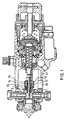
- Fig. 1 is a longitudinal cross-section of an automatic spraygun fitted with a first embodiment of a needle packing assembly according to the invention;
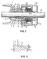
- Fig. 2 is a cross-sectional detail of the needle packing assembly; and
- Fig. 3 is an enlarged detail of a sealing lip of the annular seal.
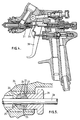
- Fig. 4 is a cross-sectional elevation of a hand-held spraygun fitted with a second embodiment of the needle packing assembly according to the invention; and
- Fig. 5 is an enlarged detail of the needle packing assembly shown in Fig. 4.
- The needle packing assembly comprises an annular seal 1 of ultra-high molecular weight plastics material such as polyethylene. The seal 1 has a cone
shaped wall 2 at one end and a bevel 3 at its other. A stepped concentric passage 4 passes through the seal with a reduced diameter 5 forming astepped shoulder 6. The outer end of the inner wall of the passage has asealing lip 7 formed by a 15° angle with the reduced diameter 5 of the inner wall as shown in the enlarged detail of Fig. 3 forming a lead in chamfer to lip T for ease of assembly of the needle. This lip engages aneedle 8 of a valve preventing ingress of the fluid being sprayed past the seal. - The needle packing assembly also comprises a sleeve shaped
liner 9 made of a lower molecular weight yieldable plastics material, such as P.T.F.E. to provide a slidable seal with theneedle 8. This liner abuts against theshoulder 6 and is forced against the shoulder by a stainlesssteel packing piece 10 formed with acollar 11 of reduced diameter around which are arranged a number of stainlesssteel disc springs 12, the other end of the packing piece having abevelled end face 13. Thesprings 12 and packingpiece 10 are forced against theliner 9 by a screw-threaded stainlesssteel packing nut 14 encircling thecollar 11 and theneedle 8, theend wall 15 of the nut applying an adjustable pressure on the springs when the nut is screwed onto asleeve 16 of thespraygun 17. - Adjustment of the
nut 14 expands theliner 9, sealing it against theneedle 8 and forces the cone shapedwall 2 against a matching taper in the sprayhead sealing it againstneedle 8 preventing ingress of the fluid material being sprayed past the seal. - To facilitate adjustment of the needle packing assembly, the body of the spraygun 17 (see Fig. 1) has an
opening 18 through which a tommy bar can be inserted to locate inholes 19 in the nut to tighten it. It will be appreciated that this adjustment can be readily carried out without having to remove the sprayhead from the spraygun. - In the second embodiment of the needle packing assembly shown in Figs. 4 and 5, the assembly is mounted in front of the
trigger 20 and comprises anannular seal 21 made of an ultra-high molecular plastics material such as polyethylene. The annular seal hascone shape ends body 24. Located in theannular seal 21 is aliner 25 of a yieldable plastics material such as P.T.F.E. which has self-lubricating properties. Anadjustable nut 26 is screw-threaded into the body 1 and has a cone shapedforward end 27 which engages the cone shapedend 23 of the annular seal and liner to force them into the gun body. By adjustment of the nut the liner expands into engagement with aneedle 28 lubricating it. This forward force applies pressure to the annular seal to force alip 29 against the needle preventing the ingress of fluid back through the seal. Any wear of the needle or liner can be adjusted by adjustment of thenut 26. - Although the most suitable material for the annular sleeve is an ultra-high molecular weight polyethylene, other ultra-high molecular weight plastics material may be used. Similarly although the liner is described as being made of a lower molecular weight yieldable plastics material, such as P.T.F.E., any suitable yieldable plastics material can be used.
Claims (11)
- A needle packing assembly for a spraygun, characterised in that it comprises an annular seal (1;21) of ultra-high molecular weight plastics material and a liner (9;25) of a yieldable plastics material of a lower molecular weight within the annular seal (1;21), a sealing lip (7;29) being formed at one end of the inner annular wall of the annular seal (1;21), the liner (9;25) being forced against the annular seal (1;21) to expand and form a self-lubricating bearing for a needle (8;28) passing through the assembly, the sealing lip (7;29) engaging the needle (8;28) to prevent the passage of a fluid past the seal (1;21).
- A needle packing assembly as claimed in Claim 1, characterised in that the annular seal (1;21) has a shoulder (6) in the interior of the seal against which the liner (9;25) abuts.
- A needle packing assembly as claimed in Claim 2, characterised in that the sealing lip (7) is formed by an angle of 15° with a reduced diameter (5) of the inner wall of the annular seal (1).
- A needle packing assembly as claimed in any preceding claim, characterised in that the annular seal (1;21) is made of polyethylene.
- A needle packing assembly as claimed in any preceding claim, characterised in that the liner (9;25) is made from P.T.F.E.
- A needle packing assembly as claimed in any preceding claim, characterised in that the liner (9) is forced against the annular seal (1) by a spring loaded packing piece (10).
- A needle packing assembly as claimed in Claim 6, characterised in that the spring pressure is applied by stainless steel disc springs (12).
- A needle packing assembly as claimed in Claims 6 or 7, characterised in that the packing piece (10) has a chamfered face (13) which engages a chamfered face (3) of the annular seal (1).
- A needle packing assembly as claimed in any of Claims 6 to 8, characterised in that the force is adjustable by a packing nut (14) engaging the springs (12) and able to be in screw-threaded engagement with a sleeve in the body of a spraygun.
- A needle packing assembly as claimed in any of Claims 1 to 5, characterised in that the liner (25) and sealing lip (29) are forced against the needle (28) when in situ in a spraygun by a screw-threaded nut (26).
- A spraygun incorporating a needle packing assembly as claimed in any preceding claim, characterised in that the body of the spraygun has an aperture to facilitate adjustment of the packing assembly.
Applications Claiming Priority (3)
| Application Number | Priority Date | Filing Date | Title |
|---|---|---|---|
| GB9002525 | 1990-02-05 | ||
| GB9002525A GB2240610B (en) | 1990-02-05 | 1990-02-05 | Needle packing assembly |
| PCT/GB1991/000166 WO1991011644A1 (en) | 1990-02-05 | 1991-02-05 | Needle packing assembly |
Publications (2)
| Publication Number | Publication Date |
|---|---|
| EP0513152A1 EP0513152A1 (en) | 1992-11-19 |
| EP0513152B1 true EP0513152B1 (en) | 1995-05-03 |
Family
ID=10670443
Family Applications (1)
| Application Number | Title | Priority Date | Filing Date |
|---|---|---|---|
| EP91903862A Expired - Lifetime EP0513152B1 (en) | 1990-02-05 | 1991-02-05 | Needle packing assembly |
Country Status (7)
| Country | Link |
|---|---|
| US (1) | US5209501A (en) |
| EP (1) | EP0513152B1 (en) |
| JP (1) | JPH04505208A (en) |
| DE (1) | DE69109467T2 (en) |
| ES (1) | ES2071985T3 (en) |
| GB (1) | GB2240610B (en) |
| WO (1) | WO1991011644A1 (en) |
Families Citing this family (31)
| Publication number | Priority date | Publication date | Assignee | Title |
|---|---|---|---|---|
| CA2047014C (en) * | 1990-07-20 | 1998-05-05 | Peter L. Frank | Air valve for portable paint gun |
| US6820824B1 (en) | 1998-01-14 | 2004-11-23 | 3M Innovative Properties Company | Apparatus for spraying liquids, disposable containers and liners suitable for use therewith |
| US7143960B2 (en) * | 2001-03-14 | 2006-12-05 | 3M Innovative Properties Company | Liquid sample reservoir suitable for use with a spraying apparatus |
| GB0210446D0 (en) * | 2002-05-08 | 2002-06-12 | 3M Innovative Properties Co | Conformable pouch reservoir for spray gun |
| GB0210448D0 (en) | 2002-05-08 | 2002-06-12 | 3M Innovative Properties Co | Valve closure for spray gun reservoir |
| US6776419B2 (en) * | 2002-06-05 | 2004-08-17 | Gregory S. Antoun | Seal for a reciprocating plunger |
| US7845582B2 (en) * | 2002-12-18 | 2010-12-07 | 3M Innovative Properties Company | Spray gun reservoir with oversize, fast-fill opening |
| US7083119B2 (en) * | 2003-09-25 | 2006-08-01 | 3M Innovative Properties Company | Security clip for spray gun connector |
| US7380680B2 (en) | 2004-01-16 | 2008-06-03 | Illinois Tool Works Inc. | Fluid supply assembly |
| US7665672B2 (en) | 2004-01-16 | 2010-02-23 | Illinois Tool Works Inc. | Antistatic paint cup |
| US7165732B2 (en) * | 2004-01-16 | 2007-01-23 | Illinois Tool Works Inc. | Adapter assembly for a fluid supply assembly |
| US7086549B2 (en) | 2004-01-16 | 2006-08-08 | Illinois Tool Works Inc. | Fluid supply assembly |
| US20050242107A1 (en) * | 2004-04-29 | 2005-11-03 | Kosmyna Michael J | Part dispenser assembly |
| US20050258271A1 (en) * | 2004-05-18 | 2005-11-24 | Kosmyna Michael J | Disposable paint cup |
| US7766250B2 (en) | 2004-06-01 | 2010-08-03 | Illinois Tool Works Inc. | Antistatic paint cup |
| US7354074B2 (en) * | 2004-06-03 | 2008-04-08 | Illinois Tool Works Inc. | Adapter assembly for a fluid supply assembly |
| US7757972B2 (en) * | 2004-06-03 | 2010-07-20 | Illinois Tool Works Inc. | Conversion adapter for a fluid supply assembly |
| US7353964B2 (en) * | 2004-06-10 | 2008-04-08 | Illinois Tool Works Inc. | Fluid supply assembly |
| EP1835997B1 (en) | 2004-12-16 | 2012-06-13 | Saint-Gobain Abrasives, Inc. | Liquid supply cup and liner assembly for spray guns |
| EP1844302A2 (en) * | 2005-01-31 | 2007-10-17 | Illinois Tool Works Inc. | Fluid supply assembly with measuring guide |
| US11040360B2 (en) | 2006-06-20 | 2021-06-22 | Saint-Gobain Abrasives, Inc. | Liquid supply assembly |
| DK2029285T3 (en) | 2006-06-20 | 2013-03-11 | Saint Gobain Abrasives Inc | The liquid supply device |
| ES1064341Y (en) * | 2006-11-24 | 2007-06-01 | Grupo Sagola Soc De Promocion | PRESS-STAPS FOR AIR GUNS |
| WO2011145162A1 (en) * | 2010-05-17 | 2011-11-24 | 株式会社島津製作所 | Seal structure of passage connecting portion |
| CA2835088C (en) | 2011-05-06 | 2018-01-16 | Saint-Gobain Abrasives, Inc. | Paint cup assembly with an extended ring |
| ES2739299T3 (en) | 2011-06-30 | 2020-01-30 | Saint Gobain Abrasives Inc | Paint container set |
| CN102401186A (en) * | 2011-07-14 | 2012-04-04 | 世林(漯河)冶金设备有限公司 | Three eccentric butterfly valve packs of cutting off pretension structure of blast furnace |
| MX2014007887A (en) | 2011-12-30 | 2014-10-06 | Saint Gobain Abrasives Inc | Convertible paint cup assembly with air inlet valve. |
| CN109578602B (en) * | 2018-11-21 | 2020-02-11 | 浙江工贸职业技术学院 | Pilot-operated stop valve |
| US20220040714A1 (en) * | 2018-12-21 | 2022-02-10 | Abb Schweiz Ag | Valve |
| US11009149B2 (en) | 2019-04-19 | 2021-05-18 | Mueller International, Llc | Bonnet and stuffing box assembly |
Family Cites Families (28)
| Publication number | Priority date | Publication date | Assignee | Title |
|---|---|---|---|---|
| US52742A (en) * | 1866-02-20 | Improvement in piston-rod packing | ||
| US801960A (en) * | 1903-07-30 | 1905-10-17 | Badeker Metallic Packing Company | Metallic packing. |
| US1444457A (en) * | 1913-04-30 | 1923-02-06 | George B Gates | Packing |
| GB123332A (en) * | 1917-03-08 | 1919-02-27 | John Sebastian Hecht | Improvements in or relating to Obturator Rings. |
| US1359428A (en) * | 1920-06-29 | 1920-11-16 | Charles H Rutherford | Grease-retainer for automobile rear axles |
| FR573510A (en) * | 1923-02-13 | 1924-06-25 | Device for ensuring the waterproofing of pressed leathers used as a gasket | |
| FR684147A (en) * | 1929-04-13 | 1930-06-21 | Sulzer Ag | Cable gland for high pressures |
| DE715496C (en) * | 1939-06-23 | 1941-12-23 | Siemens Ag | Stuffing box for sealing cable entries in electrical apparatus |
| US2307152A (en) * | 1940-11-25 | 1943-01-05 | Murray William | Packing device for rotatable or reciprocable elements |
| US2564912A (en) * | 1947-11-28 | 1951-08-21 | William H Mckissick | Stuffing box |
| DE834305C (en) * | 1949-06-08 | 1952-03-17 | Levitation Ltd | Sealing device intended for use between parts of a fluid pressure apparatus which move in a straight line with respect to one another |
| GB799991A (en) * | 1956-03-09 | 1958-08-13 | Adams Ltd L | A control valve |
| US3096096A (en) * | 1959-02-13 | 1963-07-02 | George W Banks | Sealing means for spindles of fluid valves |
| US3059937A (en) * | 1959-02-18 | 1962-10-23 | Volvo Ab | Sealing device for hydraulic systems |
| US3218087A (en) * | 1962-07-09 | 1965-11-16 | Boeing Co | Foot seal |
| GB1105606A (en) * | 1964-06-05 | 1968-03-06 | Saunders Valve Co Ltd | Means for sealing a spindle |
| BE662017A (en) * | 1964-08-13 | |||
| US3836082A (en) * | 1973-08-01 | 1974-09-17 | Binks Mfg Co | Trigger assembly for a spray gun |
| DE2609635C3 (en) * | 1976-03-09 | 1982-01-28 | Fa. J. Gg. Büttner, 8500 Nürnberg | Back sealing of a valve for hot media |
| US4131286A (en) * | 1976-06-30 | 1978-12-26 | Garlock Inc. | Seal and method for attaching seal |
| US4166579A (en) * | 1976-09-07 | 1979-09-04 | Stewart-Warner Corporation | Paint sprayer safety interlock |
| US4079950A (en) * | 1977-04-18 | 1978-03-21 | Incom International Inc. | Self-adjusting cable rod seal |
| US4353560A (en) * | 1981-12-07 | 1982-10-12 | W-K-M Wellhead Systems, Inc. | Metal seal assembly with deformable sealing ring |
| US4406468A (en) * | 1982-04-14 | 1983-09-27 | Champion Spark Plug Company | Seal assembly |
| JPS596471A (en) * | 1982-06-29 | 1984-01-13 | Iwata Tosouki Kogyo Kk | Shaft sealing device of sliding part |
| US4558874A (en) * | 1983-07-05 | 1985-12-17 | Whitey Co. | Valve stem packing assembly |
| US5050804A (en) * | 1990-08-03 | 1991-09-24 | Wagner Spray Tech Corporation | Shaft seal for portable paint gun |
| US5083749A (en) * | 1991-01-29 | 1992-01-28 | Whitey Co. | Plastic needle valve |
-
1990
- 1990-02-05 GB GB9002525A patent/GB2240610B/en not_active Expired - Fee Related
-
1991
- 1991-02-05 DE DE69109467T patent/DE69109467T2/en not_active Expired - Lifetime
- 1991-02-05 ES ES91903862T patent/ES2071985T3/en not_active Expired - Lifetime
- 1991-02-05 US US07/705,116 patent/US5209501A/en not_active Expired - Fee Related
- 1991-02-05 WO PCT/GB1991/000166 patent/WO1991011644A1/en not_active Ceased
- 1991-02-05 JP JP3504003A patent/JPH04505208A/en active Pending
- 1991-02-05 EP EP91903862A patent/EP0513152B1/en not_active Expired - Lifetime
Also Published As
| Publication number | Publication date |
|---|---|
| GB2240610A (en) | 1991-08-07 |
| EP0513152A1 (en) | 1992-11-19 |
| DE69109467D1 (en) | 1995-06-08 |
| US5209501A (en) | 1993-05-11 |
| JPH04505208A (en) | 1992-09-10 |
| DE69109467T2 (en) | 1995-09-14 |
| GB2240610B (en) | 1993-12-08 |
| WO1991011644A1 (en) | 1991-08-08 |
| GB9002525D0 (en) | 1990-04-04 |
| ES2071985T3 (en) | 1995-07-01 |
Similar Documents
| Publication | Publication Date | Title |
|---|---|---|
| US5209501A (en) | Needle packing assembly | |
| US4560109A (en) | Shaft sealing device for sliding portion of needle valve in paint spray gun | |
| US5078323A (en) | Air valve for portable paint gun | |
| US5050804A (en) | Shaft seal for portable paint gun | |
| US4331175A (en) | Mounting of pressure vessels | |
| US5014887A (en) | Valve for a container for dispensing a pressurized fluid | |
| CA1174879A (en) | Nut and thread protector | |
| US4893650A (en) | One way high pressure flow control fittings | |
| EP0179853A4 (en) | Pump for dispensing liquid from a container. | |
| US6216963B1 (en) | Device for regulating speed of deployment of sprinkler heads in preactive sprinkler systems | |
| HU208564B (en) | Pressure-limiting valve | |
| US4411439A (en) | Sealing member with anti-extrusion means and protective coating | |
| US4500119A (en) | Fluid swivel coupling | |
| EP1925859B1 (en) | Packing gland for spray guns | |
| US2545000A (en) | Valve and fitting | |
| EP1306593B1 (en) | Valve needle, used in particular in spraying of coating liquids | |
| US4288896A (en) | Method for manufacturing an improved plug valve | |
| US2781148A (en) | Quick acting closure | |
| US4958769A (en) | Compressed O-ring spray gun needle valve seal | |
| CA2047014C (en) | Air valve for portable paint gun | |
| US2878896A (en) | Lubricant fitting | |
| US5050843A (en) | Plug valve with metal-to-metal sealing | |
| US4193419A (en) | Connector apparatus for pressurized lines | |
| US2486113A (en) | Hydraulic coupler | |
| US3472254A (en) | Valve with destructible sealing means |
Legal Events
| Date | Code | Title | Description |
|---|---|---|---|
| PUAI | Public reference made under article 153(3) epc to a published international application that has entered the european phase |
Free format text: ORIGINAL CODE: 0009012 |
|
| 17P | Request for examination filed |
Effective date: 19920812 |
|
| AK | Designated contracting states |
Kind code of ref document: A1 Designated state(s): BE DE ES FR GB IT SE |
|
| 17Q | First examination report despatched |
Effective date: 19940107 |
|
| GRAA | (expected) grant |
Free format text: ORIGINAL CODE: 0009210 |
|
| AK | Designated contracting states |
Kind code of ref document: B1 Designated state(s): BE DE ES FR GB IT SE |
|
| REF | Corresponds to: |
Ref document number: 69109467 Country of ref document: DE Date of ref document: 19950608 |
|
| ITF | It: translation for a ep patent filed | ||
| REG | Reference to a national code |
Ref country code: ES Ref legal event code: FG2A Ref document number: 2071985 Country of ref document: ES Kind code of ref document: T3 |
|
| ET | Fr: translation filed | ||
| PG25 | Lapsed in a contracting state [announced via postgrant information from national office to epo] |
Ref country code: BE Effective date: 19960228 |
|
| PLBE | No opposition filed within time limit |
Free format text: ORIGINAL CODE: 0009261 |
|
| STAA | Information on the status of an ep patent application or granted ep patent |
Free format text: STATUS: NO OPPOSITION FILED WITHIN TIME LIMIT |
|
| 26N | No opposition filed | ||
| BERE | Be: lapsed |
Owner name: ITW LTD Effective date: 19960228 |
|
| PGFP | Annual fee paid to national office [announced via postgrant information from national office to epo] |
Ref country code: FR Payment date: 19970115 Year of fee payment: 7 |
|
| PGFP | Annual fee paid to national office [announced via postgrant information from national office to epo] |
Ref country code: SE Payment date: 19970116 Year of fee payment: 7 |
|
| PG25 | Lapsed in a contracting state [announced via postgrant information from national office to epo] |
Ref country code: SE Free format text: LAPSE BECAUSE OF NON-PAYMENT OF DUE FEES Effective date: 19980206 |
|
| PG25 | Lapsed in a contracting state [announced via postgrant information from national office to epo] |
Ref country code: FR Free format text: THE PATENT HAS BEEN ANNULLED BY A DECISION OF A NATIONAL AUTHORITY Effective date: 19980228 |
|
| EUG | Se: european patent has lapsed |
Ref document number: 91903862.0 |
|
| REG | Reference to a national code |
Ref country code: FR Ref legal event code: ST |
|
| REG | Reference to a national code |
Ref country code: GB Ref legal event code: IF02 |
|
| PGFP | Annual fee paid to national office [announced via postgrant information from national office to epo] |
Ref country code: ES Payment date: 20100225 Year of fee payment: 20 |
|
| PGFP | Annual fee paid to national office [announced via postgrant information from national office to epo] |
Ref country code: IT Payment date: 20100224 Year of fee payment: 20 |
|
| PGFP | Annual fee paid to national office [announced via postgrant information from national office to epo] |
Ref country code: GB Payment date: 20100224 Year of fee payment: 20 Ref country code: DE Payment date: 20100226 Year of fee payment: 20 |
|
| REG | Reference to a national code |
Ref country code: DE Ref legal event code: R071 Ref document number: 69109467 Country of ref document: DE |
|
| REG | Reference to a national code |
Ref country code: GB Ref legal event code: PE20 Expiry date: 20110204 |
|
| REG | Reference to a national code |
Ref country code: ES Ref legal event code: FD2A Effective date: 20110302 |
|
| PG25 | Lapsed in a contracting state [announced via postgrant information from national office to epo] |
Ref country code: GB Free format text: LAPSE BECAUSE OF EXPIRATION OF PROTECTION Effective date: 20110204 Ref country code: ES Free format text: LAPSE BECAUSE OF EXPIRATION OF PROTECTION Effective date: 20110206 |
|
| PG25 | Lapsed in a contracting state [announced via postgrant information from national office to epo] |
Ref country code: DE Free format text: LAPSE BECAUSE OF EXPIRATION OF PROTECTION Effective date: 20110205 |