EP0513093B1 - A capacitive force transducer - Google Patents
A capacitive force transducer Download PDFInfo
- Publication number
- EP0513093B1 EP0513093B1 EP91903234A EP91903234A EP0513093B1 EP 0513093 B1 EP0513093 B1 EP 0513093B1 EP 91903234 A EP91903234 A EP 91903234A EP 91903234 A EP91903234 A EP 91903234A EP 0513093 B1 EP0513093 B1 EP 0513093B1
- Authority
- EP
- European Patent Office
- Prior art keywords
- plates
- transducer assembly
- assembly according
- flanges
- load
- Prior art date
- Legal status (The legal status is an assumption and is not a legal conclusion. Google has not performed a legal analysis and makes no representation as to the accuracy of the status listed.)
- Expired - Lifetime
Links
- 239000003990 capacitor Substances 0.000 claims abstract description 21
- 238000006073 displacement reaction Methods 0.000 claims abstract description 6
- 230000007423 decrease Effects 0.000 claims abstract description 4
- 230000000712 assembly Effects 0.000 claims 3
- 238000000429 assembly Methods 0.000 claims 3
- 239000003989 dielectric material Substances 0.000 claims 1
- 230000000694 effects Effects 0.000 description 2
- 229910000906 Bronze Inorganic materials 0.000 description 1
- 229920001875 Ebonite Polymers 0.000 description 1
- 239000004677 Nylon Substances 0.000 description 1
- 239000000853 adhesive Substances 0.000 description 1
- 230000001070 adhesive effect Effects 0.000 description 1
- 230000002411 adverse Effects 0.000 description 1
- 239000010974 bronze Substances 0.000 description 1
- 230000006835 compression Effects 0.000 description 1
- 238000007906 compression Methods 0.000 description 1
- 238000010276 construction Methods 0.000 description 1
- 230000008878 coupling Effects 0.000 description 1
- 238000010168 coupling process Methods 0.000 description 1
- 238000005859 coupling reaction Methods 0.000 description 1
- 230000001419 dependent effect Effects 0.000 description 1
- 239000000428 dust Substances 0.000 description 1
- 229920001971 elastomer Polymers 0.000 description 1
- 230000001939 inductive effect Effects 0.000 description 1
- 229920001778 nylon Polymers 0.000 description 1
- 238000012856 packing Methods 0.000 description 1
- 239000012858 resilient material Substances 0.000 description 1
- 239000005060 rubber Substances 0.000 description 1
- 125000006850 spacer group Chemical group 0.000 description 1
- 229910001220 stainless steel Inorganic materials 0.000 description 1
- 239000010935 stainless steel Substances 0.000 description 1
- 229920003051 synthetic elastomer Polymers 0.000 description 1
- 239000005061 synthetic rubber Substances 0.000 description 1
- 239000011800 void material Substances 0.000 description 1
- 238000004804 winding Methods 0.000 description 1
Images

Classifications
-
- B—PERFORMING OPERATIONS; TRANSPORTING
- B60—VEHICLES IN GENERAL
- B60T—VEHICLE BRAKE CONTROL SYSTEMS OR PARTS THEREOF; BRAKE CONTROL SYSTEMS OR PARTS THEREOF, IN GENERAL; ARRANGEMENT OF BRAKING ELEMENTS ON VEHICLES IN GENERAL; PORTABLE DEVICES FOR PREVENTING UNWANTED MOVEMENT OF VEHICLES; VEHICLE MODIFICATIONS TO FACILITATE COOLING OF BRAKES
- B60T7/00—Brake-action initiating means
- B60T7/12—Brake-action initiating means for automatic initiation; for initiation not subject to will of driver or passenger
- B60T7/20—Brake-action initiating means for automatic initiation; for initiation not subject to will of driver or passenger specially for trailers, e.g. in case of uncoupling of or overrunning by trailer
-
- G—PHYSICS
- G01—MEASURING; TESTING
- G01L—MEASURING FORCE, STRESS, TORQUE, WORK, MECHANICAL POWER, MECHANICAL EFFICIENCY, OR FLUID PRESSURE
- G01L1/00—Measuring force or stress, in general
- G01L1/14—Measuring force or stress, in general by measuring variations in capacitance or inductance of electrical elements, e.g. by measuring variations of frequency of electrical oscillators
- G01L1/142—Measuring force or stress, in general by measuring variations in capacitance or inductance of electrical elements, e.g. by measuring variations of frequency of electrical oscillators using capacitors
- G01L1/144—Measuring force or stress, in general by measuring variations in capacitance or inductance of electrical elements, e.g. by measuring variations of frequency of electrical oscillators using capacitors with associated circuitry
-
- G—PHYSICS
- G01—MEASURING; TESTING
- G01L—MEASURING FORCE, STRESS, TORQUE, WORK, MECHANICAL POWER, MECHANICAL EFFICIENCY, OR FLUID PRESSURE
- G01L5/00—Apparatus for, or methods of, measuring force, work, mechanical power, or torque, specially adapted for specific purposes
- G01L5/13—Apparatus for, or methods of, measuring force, work, mechanical power, or torque, specially adapted for specific purposes for measuring the tractive or propulsive power of vehicles
- G01L5/136—Force sensors associated with a vehicle traction coupling
Definitions
- This invention relates to a transducer designed to produce an electrical output signal dependent on a mechanically applied force.
- Such transducers find wide use in control systems of various kinds and the most commonly employed transducers rely either on variable inductance (a core or armature moving axially through a pair of aligned coils connected in a balanced circuit) or variable resistance e.g. strain gauges.
- Variable capacitance transducers are also known but are less widely used as it generally assumed that the severely non-linear characteristic (the relationship between displacement and capacitance is hyperbolic) makes them impractical and furthermore, unless very large- area electrodes or multi-plate arrangements are used, the absolute value of the capacitance involved is very small and the changes with displacement can be swamped by stray capacitance from leads and other components.
- variable capacitance has its place in the field of transducers, and advantage can be taken of its characteristics which include simplicity and the ability to withstand an adverse environment.
- a particular need for a rugged electro-mechanical transducer arises in the automatic control of the braking of trailer vehicles. It has been appreciated that in a vehicle assembly, especially a road vehicle assembly, comprising a tractor and trailer (or semi-trailer) with the brakes applied on both vehicles from a source on the tractor, it is desirable to match the relative braking effort in the two vehicles to one another under all load conditions, so that the two vehicles are braked equally, regardless of whether, for example, the trailer is empty or fully loaded.
- the aim of the present invention therefore is to put forward a novel variable capacitance transducer of simple and rugged construction suitable for use in hostile environments.
- an electro-mechanical transducer assembly of the variable capacitance type comprising a first load-transmitting member having a central axis and extending through a second load-transmitting member comprising two axially spaced flanges on the first member lying on opposite sides of a transversely extending portion of the second member, resilient means for transmitting axial loads between each of the flanges and the said portion between them, whereby forces in both axial directions can be resiliently transmitted, the resilient means being symmetrically disposed around the axis, and electrical capacitor plates mounted on, or associated with, both flanges and both faces of the said portion of the second member, the plates being distributed symmetrically around those flanges and that portion, so that on relative axial displacement of the members under load in either direction the capacitance between the plates on one side of the portion increases while that on the other side decreases. It will be appreciated that the symmetrical disposition of the capacitor plates substantially nullifies the effect of non-axial forces on the assembly.
- the resilient means can comprise disc springs.
- the capacitors are not individual capacitors spaced around the axis but are of annular form, the plates being in the form of rings encircling the first-mentioned force-transmitting member.
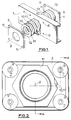
- the drawbeam i.e. the transverse chassis member of a towing vehicle through which the towing load is taken
- the drawbar itself is omitted for clarity and so is the hitch assembly to which the drawbar is detachably secured, but the main pin of the hitch assembly lies on the axis indicated at 2 and has secured to it two substantial flanges 3 and 4.
- Four symmetrically placed bolts passing through holes in the flanges and the drawbeam transmit the towing load, and in fact this is a standard layout, with an ISO standard applicable to the positions of the holes. In the standard arrangements the assembly would be tight, with no play between the flanges and the drawbeam except possibly some hard rubber packing to give a slight degree of resilience.
- capacitors formed by annular electrodes surrounding the main pin of the hitch.
- two electrodes 10 and 11 are insulated from the drawbeam and the adjacent flange by insulating rings 12 and are spaced apart from one another by a ring of dielectric 13, preferably nylon.
- An alternative to putting a wave in each electrode would be to make the dielectric wavy.
- One way of doing this would be to apply evenly circumferentially spaced radial ribs, e.g. by adhesive, to opposite sides of the dielectric alternately, so that they are staggered, for example six each side.
- a further possibility is to use a dielectric of resilient material such as synthetic rubber, but considerable void space is necessary to accommodate the displaced rubber.
- each capacitor has a mean value of about 470pf. If desired, one could increase the capacitance by inserting further ring-shaped electrodes and dielectric rings between them, connecting them alternately in pairs.
- a given assembly with a given travel between zero and full load, can be designed for trailers of anything from, for example, 10 to 70 tons in weight. It will be appreciated that in the layout described the functions of transmitting the load and of generating the electrical signal are kept totally independent, i.e. the loads on the drawbar are not transmitted through the capacitor plates or through any parts associated with them.
- Dust seals or boots 14 extend around the gaps between the flanges and the drawbeam, but even if weather does penetrate the seals, the simple capacitor sensors are relatively insensitive to damage or failure, in contrast, for example, to delicate inductive transducers.
- Figure 4 shows a layout in which the two capacitors, shown at A and B are connected in a half-bridge circuit and driven by anti-phase AC voltages of for example 1 volt peak-to-peak obtained from a centre-tapped secondary winding on the coil of a free-running oscillator which, in a typical case, operates at a frequency of 5kHz.
- the output signal from the sensor is AC coupled into the virtual earth of an amplifier; this eliminates the effect of capacitance of the connecting cables and other stray capacitances to earth.
- the output of the amplifier is then compared in a phase detector circuit with a reference signal from the oscillator to produce a bipolar output signal which, in a typical case, may range between + and - 5 volts.
- the combination of the transducer, oscillator, amplifier and phase detector is capable of giving an approximately linear indication of both compressive and tensile forces in the drawbar.
Landscapes
- Engineering & Computer Science (AREA)
- Chemical & Material Sciences (AREA)
- Physics & Mathematics (AREA)
- General Physics & Mathematics (AREA)
- Combustion & Propulsion (AREA)
- Mechanical Engineering (AREA)
- Power Engineering (AREA)
- Analytical Chemistry (AREA)
- Transportation (AREA)
- Transmission And Conversion Of Sensor Element Output (AREA)
- Measurement Of Length, Angles, Or The Like Using Electric Or Magnetic Means (AREA)
- Transmission Devices (AREA)
- Powder Metallurgy (AREA)
- Ceramic Products (AREA)
- Carbon And Carbon Compounds (AREA)
Applications Claiming Priority (3)
| Application Number | Priority Date | Filing Date | Title |
|---|---|---|---|
| GB9002433 | 1990-02-03 | ||
| GB909002433A GB9002433D0 (en) | 1990-02-03 | 1990-02-03 | Transducers |
| PCT/GB1991/000141 WO1991011351A1 (en) | 1990-02-03 | 1991-01-31 | A capacitive force transducer |
Publications (2)
| Publication Number | Publication Date |
|---|---|
| EP0513093A1 EP0513093A1 (en) | 1992-11-19 |
| EP0513093B1 true EP0513093B1 (en) | 1995-04-05 |
Family
ID=10670378
Family Applications (1)
| Application Number | Title | Priority Date | Filing Date |
|---|---|---|---|
| EP91903234A Expired - Lifetime EP0513093B1 (en) | 1990-02-03 | 1991-01-31 | A capacitive force transducer |
Country Status (9)
| Country | Link |
|---|---|
| US (1) | US5289435A (cs) |
| EP (1) | EP0513093B1 (cs) |
| JP (1) | JPH05504406A (cs) |
| AU (1) | AU7230991A (cs) |
| CS (1) | CS24591A2 (cs) |
| DE (1) | DE69108715T2 (cs) |
| ES (1) | ES2070490T3 (cs) |
| GB (1) | GB9002433D0 (cs) |
| WO (1) | WO1991011351A1 (cs) |
Families Citing this family (11)
| Publication number | Priority date | Publication date | Assignee | Title |
|---|---|---|---|---|
| DE4027753C2 (de) * | 1990-09-01 | 1994-06-09 | Karlheinz Dr Ziegler | Kapazitiver Kraftsensor |
| GB9209259D0 (en) * | 1992-04-29 | 1992-06-17 | Bloxwich Eng | Fifth wheel coupling |
| FR2716509B1 (fr) * | 1994-01-19 | 1996-04-12 | Alliedsignal Automotive Espana | Frein à disque à sécurité accrue. |
| GB9405960D0 (en) * | 1994-03-25 | 1994-05-11 | Bloxwich Eng Ltd | Sensor |
| DE19708144A1 (de) * | 1997-02-28 | 1998-09-03 | Itt Mfg Enterprises Inc | Verfahren zur Vermeidung von Pendelbewegungen der Deichsel eines Kfz.-Anhängers |
| DE19805687B4 (de) * | 1998-02-12 | 2010-11-11 | Alcatel Lucent | Vorrichtung zum Ermitteln einer Kraft |
| US6302424B1 (en) | 1999-12-09 | 2001-10-16 | Holland Hitch Company | Force-sensing fifth wheel |
| DE10101973B4 (de) * | 2001-01-17 | 2007-10-04 | Pacifica Group Technologies Pty Ltd | Kraftsensor zur Messung einer Kraft im Kraftfluss |
| US8607640B2 (en) * | 2010-07-19 | 2013-12-17 | Odd Harald Steen Eriksen | Sensor for measuring large mechanical strains in shear or lateral translation |
| US10131419B2 (en) | 2010-10-15 | 2018-11-20 | Goodrich Corporation | Systems and methods for detecting landing gear ground loads |
| US9848775B2 (en) * | 2013-05-22 | 2017-12-26 | The Board Of Trustees Of The Leland Stanford Junior University | Passive and wireless pressure sensor |
Family Cites Families (12)
| Publication number | Priority date | Publication date | Assignee | Title |
|---|---|---|---|---|
| US2653306A (en) * | 1949-10-03 | 1953-09-22 | Phillips Petroleum Co | Seismometer |
| US2677272A (en) * | 1950-01-23 | 1954-05-04 | Bendix Aviat Corp | Stress indicating apparatus |
| US3033031A (en) * | 1959-07-27 | 1962-05-08 | Waukesha Bearings Corp | Tilting pad type thrust bearings having integral means for measuring thrust loads |
| GB1201755A (en) * | 1969-02-26 | 1970-08-12 | Ford Motor Co | Axle load measurement |
| US3577883A (en) * | 1969-06-26 | 1971-05-11 | Rosemount Eng Co Ltd | Capacitive strain sensor |
| US4197753A (en) * | 1970-04-30 | 1980-04-15 | The Boeing Company | Strain gage |
| CH583110A5 (en) * | 1975-05-23 | 1976-12-31 | Beka St Aubin Sa | Trailer brake system actuated by coupling pressure - has pressure sensitive resistor for generating signals for actuating brake solenoids |
| US4062229A (en) * | 1977-02-22 | 1977-12-13 | General Electric Company | Method of testing the integrity of installed rock bolts |
| SU815577A1 (ru) * | 1978-07-03 | 1981-03-23 | Kochev Viktor M | Самоцентрирующийс захват |
| US4386533A (en) * | 1981-01-26 | 1983-06-07 | Deere & Company | Capacitance transducer |
| FI75122C (fi) * | 1986-03-20 | 1988-05-09 | Jorma Saramo | Anordning foer automatisk sammanpassning av tryckluftbromsarna hos en motordriven fordonskombination. |
| DE3842037A1 (de) * | 1988-12-14 | 1990-06-28 | Wabco Westinghouse Fahrzeug | Einrichtung zur erfassung einer axialkraft einer deichselkupplung |
-
1990
- 1990-02-03 GB GB909002433A patent/GB9002433D0/en active Pending
-
1991
- 1991-01-31 AU AU72309/91A patent/AU7230991A/en not_active Abandoned
- 1991-01-31 JP JP3503905A patent/JPH05504406A/ja active Pending
- 1991-01-31 ES ES91903234T patent/ES2070490T3/es not_active Expired - Lifetime
- 1991-01-31 EP EP91903234A patent/EP0513093B1/en not_active Expired - Lifetime
- 1991-01-31 DE DE69108715T patent/DE69108715T2/de not_active Expired - Fee Related
- 1991-01-31 WO PCT/GB1991/000141 patent/WO1991011351A1/en not_active Ceased
- 1991-02-01 CS CS91245A patent/CS24591A2/cs unknown
-
1992
- 1992-07-27 US US07/915,730 patent/US5289435A/en not_active Expired - Fee Related
Also Published As
| Publication number | Publication date |
|---|---|
| AU7230991A (en) | 1991-08-21 |
| CS24591A2 (en) | 1991-09-15 |
| GB9002433D0 (en) | 1990-04-04 |
| US5289435A (en) | 1994-02-22 |
| ES2070490T3 (es) | 1995-06-01 |
| WO1991011351A1 (en) | 1991-08-08 |
| EP0513093A1 (en) | 1992-11-19 |
| JPH05504406A (ja) | 1993-07-08 |
| DE69108715T2 (de) | 1995-08-17 |
| DE69108715D1 (de) | 1995-05-11 |
Similar Documents
| Publication | Publication Date | Title |
|---|---|---|
| EP0513093B1 (en) | A capacitive force transducer | |
| CN1065959C (zh) | 带应力隔离凹槽的压力变送器 | |
| US4474060A (en) | Torque readout sensor | |
| JP2736929B2 (ja) | 牽引棒連結器の軸線方向力を検出するための装置 | |
| EP0515425B1 (en) | Controlling braking forces in tractor-trailer combinations | |
| US3678378A (en) | Capacitors | |
| US5176368A (en) | Vehicle engine mount | |
| US5149121A (en) | Force measuring device | |
| EP0211519A2 (en) | Capacitive differential pressure transducer | |
| JPH01132411A (ja) | 力測定装置 | |
| EP0091282B1 (en) | Load sensor, e.g. for sensing a vehicle draft load | |
| EP0428890A3 (en) | Trailer coupling with load cell | |
| US11661046B2 (en) | Pedal feel emulator assembly and a brake system including the pedal feel emulator assembly | |
| US4386312A (en) | Linear capacitive sensor system | |
| US4507972A (en) | Pressure gauge | |
| KR100479250B1 (ko) | 자동차용 제동장치 | |
| DE3627127C2 (cs) | ||
| US3828294A (en) | Acceleration transducer having semiconductive piezoresistive element | |
| GB2275117A (en) | Load-sensing in draw-bar couplings for vehicles | |
| US3797302A (en) | On-board aircraft weight transducer with mechanical offset adjustment | |
| US11454522B2 (en) | System to be coupled to a cardan shaft, related cardan shaft and operation method of said system | |
| US4845999A (en) | Magnetoelastic torque transducer with double sleeve | |
| GB2256718A (en) | Load-measuring method and apparatus for vehicles | |
| JP2533142Y2 (ja) | 荷重センサ | |
| GB2078983A (en) | Force transducers |
Legal Events
| Date | Code | Title | Description |
|---|---|---|---|
| PUAI | Public reference made under article 153(3) epc to a published international application that has entered the european phase |
Free format text: ORIGINAL CODE: 0009012 |
|
| 17P | Request for examination filed |
Effective date: 19920829 |
|
| AK | Designated contracting states |
Kind code of ref document: A1 Designated state(s): DE ES FR GB IT SE |
|
| 17Q | First examination report despatched |
Effective date: 19930917 |
|
| GRAA | (expected) grant |
Free format text: ORIGINAL CODE: 0009210 |
|
| AK | Designated contracting states |
Kind code of ref document: B1 Designated state(s): DE ES FR GB IT SE |
|
| ITF | It: translation for a ep patent filed | ||
| REF | Corresponds to: |
Ref document number: 69108715 Country of ref document: DE Date of ref document: 19950511 |
|
| REG | Reference to a national code |
Ref country code: ES Ref legal event code: FG2A Ref document number: 2070490 Country of ref document: ES Kind code of ref document: T3 |
|
| ET | Fr: translation filed | ||
| PLBE | No opposition filed within time limit |
Free format text: ORIGINAL CODE: 0009261 |
|
| STAA | Information on the status of an ep patent application or granted ep patent |
Free format text: STATUS: NO OPPOSITION FILED WITHIN TIME LIMIT |
|
| 26N | No opposition filed | ||
| PGFP | Annual fee paid to national office [announced via postgrant information from national office to epo] |
Ref country code: GB Payment date: 20001211 Year of fee payment: 11 |
|
| PGFP | Annual fee paid to national office [announced via postgrant information from national office to epo] |
Ref country code: SE Payment date: 20010103 Year of fee payment: 11 Ref country code: FR Payment date: 20010103 Year of fee payment: 11 |
|
| PGFP | Annual fee paid to national office [announced via postgrant information from national office to epo] |
Ref country code: ES Payment date: 20010123 Year of fee payment: 11 |
|
| PGFP | Annual fee paid to national office [announced via postgrant information from national office to epo] |
Ref country code: DE Payment date: 20010126 Year of fee payment: 11 |
|
| REG | Reference to a national code |
Ref country code: GB Ref legal event code: IF02 |
|
| PG25 | Lapsed in a contracting state [announced via postgrant information from national office to epo] |
Ref country code: GB Free format text: LAPSE BECAUSE OF NON-PAYMENT OF DUE FEES Effective date: 20020131 |
|
| PG25 | Lapsed in a contracting state [announced via postgrant information from national office to epo] |
Ref country code: SE Free format text: LAPSE BECAUSE OF NON-PAYMENT OF DUE FEES Effective date: 20020201 Ref country code: ES Free format text: LAPSE BECAUSE OF NON-PAYMENT OF DUE FEES Effective date: 20020201 |
|
| PG25 | Lapsed in a contracting state [announced via postgrant information from national office to epo] |
Ref country code: DE Free format text: LAPSE BECAUSE OF NON-PAYMENT OF DUE FEES Effective date: 20020801 |
|
| GBPC | Gb: european patent ceased through non-payment of renewal fee |
Effective date: 20020131 |
|
| EUG | Se: european patent has lapsed |
Ref document number: 91903234.2 |
|
| PG25 | Lapsed in a contracting state [announced via postgrant information from national office to epo] |
Ref country code: FR Free format text: LAPSE BECAUSE OF NON-PAYMENT OF DUE FEES Effective date: 20020930 |
|
| REG | Reference to a national code |
Ref country code: FR Ref legal event code: ST |
|
| REG | Reference to a national code |
Ref country code: ES Ref legal event code: FD2A Effective date: 20030211 |
|
| PG25 | Lapsed in a contracting state [announced via postgrant information from national office to epo] |
Ref country code: IT Free format text: LAPSE BECAUSE OF NON-PAYMENT OF DUE FEES;WARNING: LAPSES OF ITALIAN PATENTS WITH EFFECTIVE DATE BEFORE 2007 MAY HAVE OCCURRED AT ANY TIME BEFORE 2007. THE CORRECT EFFECTIVE DATE MAY BE DIFFERENT FROM THE ONE RECORDED. Effective date: 20050131 |