EP0512853B1 - Ventilated-type disc rotor - Google Patents
Ventilated-type disc rotor Download PDFInfo
- Publication number
- EP0512853B1 EP0512853B1 EP92304159A EP92304159A EP0512853B1 EP 0512853 B1 EP0512853 B1 EP 0512853B1 EP 92304159 A EP92304159 A EP 92304159A EP 92304159 A EP92304159 A EP 92304159A EP 0512853 B1 EP0512853 B1 EP 0512853B1
- Authority
- EP
- European Patent Office
- Prior art keywords
- disc
- internal
- external
- ribs
- cylindrical member
- Prior art date
- Legal status (The legal status is an assumption and is not a legal conclusion. Google has not performed a legal analysis and makes no representation as to the accuracy of the status listed.)
- Expired - Lifetime
Links
- 230000002093 peripheral effect Effects 0.000 claims description 31
- 238000001816 cooling Methods 0.000 claims description 17
- 230000037361 pathway Effects 0.000 claims description 16
- 230000004323 axial length Effects 0.000 claims description 3
- 230000002787 reinforcement Effects 0.000 description 10
- 238000005266 casting Methods 0.000 description 5
- 230000015572 biosynthetic process Effects 0.000 description 2
- 238000005520 cutting process Methods 0.000 description 2
- 230000000694 effects Effects 0.000 description 2
- 238000010276 construction Methods 0.000 description 1
- 230000004048 modification Effects 0.000 description 1
- 238000012986 modification Methods 0.000 description 1
Images








Classifications
-
- F—MECHANICAL ENGINEERING; LIGHTING; HEATING; WEAPONS; BLASTING
- F16—ENGINEERING ELEMENTS AND UNITS; GENERAL MEASURES FOR PRODUCING AND MAINTAINING EFFECTIVE FUNCTIONING OF MACHINES OR INSTALLATIONS; THERMAL INSULATION IN GENERAL
- F16D—COUPLINGS FOR TRANSMITTING ROTATION; CLUTCHES; BRAKES
- F16D65/00—Parts or details
- F16D65/02—Braking members; Mounting thereof
- F16D65/12—Discs; Drums for disc brakes
- F16D65/123—Discs; Drums for disc brakes comprising an annular disc secured to a hub member; Discs characterised by means for mounting
-
- F—MECHANICAL ENGINEERING; LIGHTING; HEATING; WEAPONS; BLASTING
- F16—ENGINEERING ELEMENTS AND UNITS; GENERAL MEASURES FOR PRODUCING AND MAINTAINING EFFECTIVE FUNCTIONING OF MACHINES OR INSTALLATIONS; THERMAL INSULATION IN GENERAL
- F16D—COUPLINGS FOR TRANSMITTING ROTATION; CLUTCHES; BRAKES
- F16D65/00—Parts or details
- F16D65/02—Braking members; Mounting thereof
- F16D65/12—Discs; Drums for disc brakes
- F16D65/128—Discs; Drums for disc brakes characterised by means for cooling
-
- F—MECHANICAL ENGINEERING; LIGHTING; HEATING; WEAPONS; BLASTING
- F16—ENGINEERING ELEMENTS AND UNITS; GENERAL MEASURES FOR PRODUCING AND MAINTAINING EFFECTIVE FUNCTIONING OF MACHINES OR INSTALLATIONS; THERMAL INSULATION IN GENERAL
- F16D—COUPLINGS FOR TRANSMITTING ROTATION; CLUTCHES; BRAKES
- F16D65/00—Parts or details
- F16D65/02—Braking members; Mounting thereof
- F16D2065/13—Parts or details of discs or drums
- F16D2065/1304—Structure
- F16D2065/1316—Structure radially segmented
-
- F—MECHANICAL ENGINEERING; LIGHTING; HEATING; WEAPONS; BLASTING
- F16—ENGINEERING ELEMENTS AND UNITS; GENERAL MEASURES FOR PRODUCING AND MAINTAINING EFFECTIVE FUNCTIONING OF MACHINES OR INSTALLATIONS; THERMAL INSULATION IN GENERAL
- F16D—COUPLINGS FOR TRANSMITTING ROTATION; CLUTCHES; BRAKES
- F16D65/00—Parts or details
- F16D65/02—Braking members; Mounting thereof
- F16D2065/13—Parts or details of discs or drums
- F16D2065/1304—Structure
- F16D2065/132—Structure layered
-
- F—MECHANICAL ENGINEERING; LIGHTING; HEATING; WEAPONS; BLASTING
- F16—ENGINEERING ELEMENTS AND UNITS; GENERAL MEASURES FOR PRODUCING AND MAINTAINING EFFECTIVE FUNCTIONING OF MACHINES OR INSTALLATIONS; THERMAL INSULATION IN GENERAL
- F16D—COUPLINGS FOR TRANSMITTING ROTATION; CLUTCHES; BRAKES
- F16D65/00—Parts or details
- F16D65/02—Braking members; Mounting thereof
- F16D2065/13—Parts or details of discs or drums
- F16D2065/1304—Structure
- F16D2065/1328—Structure internal cavities, e.g. cooling channels
-
- F—MECHANICAL ENGINEERING; LIGHTING; HEATING; WEAPONS; BLASTING
- F16—ENGINEERING ELEMENTS AND UNITS; GENERAL MEASURES FOR PRODUCING AND MAINTAINING EFFECTIVE FUNCTIONING OF MACHINES OR INSTALLATIONS; THERMAL INSULATION IN GENERAL
- F16D—COUPLINGS FOR TRANSMITTING ROTATION; CLUTCHES; BRAKES
- F16D65/00—Parts or details
- F16D65/02—Braking members; Mounting thereof
- F16D2065/13—Parts or details of discs or drums
- F16D2065/134—Connection
- F16D2065/1344—Connection permanent, e.g. by casting
-
- F—MECHANICAL ENGINEERING; LIGHTING; HEATING; WEAPONS; BLASTING
- F16—ENGINEERING ELEMENTS AND UNITS; GENERAL MEASURES FOR PRODUCING AND MAINTAINING EFFECTIVE FUNCTIONING OF MACHINES OR INSTALLATIONS; THERMAL INSULATION IN GENERAL
- F16D—COUPLINGS FOR TRANSMITTING ROTATION; CLUTCHES; BRAKES
- F16D65/00—Parts or details
- F16D65/02—Braking members; Mounting thereof
- F16D2065/13—Parts or details of discs or drums
- F16D2065/134—Connection
- F16D2065/1356—Connection interlocking
Definitions
- This invention relates to a ventilated type disc rotor to be used for a braking system of a vehicle, the rotor comprising :
- DE-A-2,942,151 and DE-A-4,013,244 disclose rotors broadly in accordance with the foregoing description, although the former text is directed especially to the material by which the hub and a friction disc are joined together, and the latter text to the form of a collar on the hub where it meets the discs.
- a disc rotor which is generally designated by reference numeral 1 in these Figures comprises an internal disc 2 and an external disc 3 disposed in a face-to-face relationship with a number of ribs 4 radially arranged between the discs to provide pathways 5 for cooling air defined by any two adjacent ribs so that the two discs are frictionally pressed against each other by way of a brake pad for braking the vehicle and the heat generated on the frictional surfaces of the discs is moved away from there with the air to cool the heated discs.
- the external disc 3 is connected at its inner periphery to a cylindrical member 6, which is by turn connected to the outer periphery of a fitting plate 7 that constitutes a flange to be secured to the vehicle main body.
- Said fitting plate 7 is provided with a central bore 8, fitting holes 9 and auxiliary holes 10 arranged for making the operation of removing said disc rotor from the vehicle main body be carried out without difficulty.
- a known ventilated-type disc rotor as described above is accompanied by a drawback of presenting a phenomenon of thermal deformation of the internal and external discs 2 and 3, which is typically illustrated by broken lines in Figure 18, due to the heat generated on these discs 2 and 3 particularly when the vehicle's brakes are applied while the wheel shafts are rotating at high speed or when the brakes are applied frequently within a short period of time.
- the above object is achieved by providing a ventilated-type disc rotor as set out in the opening paragraph of the present specification, in which
- the frictional surfaces of the external and internal discs are connected only to the ribs and not to the cylindrical member which is fitted to the outer periphery of a flange to be fitted to the main body of a vehicle and a gap is provided between the inner periphery of the external disc and the outer peripheral surface of the cylindrical member, the overall cooling effect of the disc rotor is significantly improved and the thermal deformation of the discs can be minimized because the external disc and the cylindrical member are connected to each other only by way of the radially arranged thick ribs which normally remain cooler than the frictionally heated discs so that the internal stress of the external disc can be reduced and any possibility of occurrence of cracks can be eliminated to improve the abutment of the brake pad and the disc rotor and consequently their durability.
- a bulge is formed on an outer peripheral surface of the cylindrical member.
- the radial ribs comprise first ribs and second ribs which are arranged alternately, with an inner end of each of the first ribs extending radially from inner peripheral surfaces of the internal and external discs toward a centre of the internal and external discs, the second ribs being recessed radially and outwardly from the inner peripheral surfaces of the external and internal discs, and the inner end of each of the first ribs being continuously connected to the internal end of the cylindrical member.
- Desired numbers of bulged reinforcement sections may be formed at and near the inner ends of the ribs.
- Said bulged reinforcement section may be a bridge continuously connecting the inner ends of adjacent ribs to each other in a space between the ends.
- a bulge may be formed on an outer peripheral surface of said cylindrical member.
- the said bulged reinforcement section may be a broadened section at and near the inner end of the rib.
- the said bulged reinforcement section may comprise a broadened section at and near the inner end of the rib and a bridge connecting adjacent broadened sections of a desired number of ribs.
- said bulged reinforcement section may be a bridge arranged in a gap between the inner peripheral surface of the external disc and the outer peripheral surface of the cylindrical member.
- a first rib and a second rib may be arranged alternately, an inner end of said first rib extending radially and inwardly from the inner peripheral surfaces of the external and internal discs, the second rib may be recessed radially and outwardly from the inner peripheral surfaces of the external and internal discs, said first rib may be provided with a broadened section at and near the inner end, and an air pathway may extend to the cylindrical member. Any of these forms of reinforcement may be realized without increasing the number of steps required for producing a ventilated-type disc rotor by casting.
- a ventilated-type disc rotor 1 according to the invention comprises an external disc 11 and an internal disc 12 juxtaposed in a face-to-face relationship and integrally formed with a number of ribs 13 arranged radially therebetween.
- the external disc 11, the internal disc 12 and the ribs 13 may be prepared into a single piece by casting.
- An inner end 14 of the rib 13 radially extends from inner periphery surfaces 15, 16 of the external and internal disc 11, 12 toward the center of the discs.
- the inner end 14 of the rib 13 is integrally connected to a cylindrical member 19.
- the cylindrical member 19 is integrally connected to an outer periphery 18 of a fitting plate 17 which is used for securely fitting the ventilated-type disc rotor 1 to a body of a vehicle.
- the external disc 11, the internal disc 12, the ribs 13, the cylindrical member 19 and the fitting plate or flange are integrally formed by casting to form them as one piece.
- the fitting flange may be welded and the remaining components may be cast and connected to the welded flange so as to form them as one piece.
- any known arts may be utilized to produce an assembly of the discs, the ribs, the cylindrical member and the fitting flange as one piece.
- a gap 21 is formed between an inner peripheral surface 15 of the external disc 11 and an outer peripheral surface 20 of the cylindrical member 19.
- the fitting plate 17 is provided with a central bore 8, fitting holes 9 and auxiliary holes 10 in a conventional manner.
- Figs. 3 through 6 illustrate the second and third embodiments of the invention.
- a bridge 22 of a bulged reinforcement section 13A is formed with every other space 14A between an inner end 14 of a rib 13 and an inner end 14 the adjacent rib 13.
- the bridge 22 is alternately formed in the space 14A.
- Pathways 23, 24 for cooling air are formed at an lower end of the cylindrical body 19 between the external disc 11 and the internal disc 12. Since the inner end 14 of the ribs 13 is continuously connected to the cylindrical member 19 as illustrated in Figs. 3 and 5, the pathway 24 is narrowed by the thickness of the respective bridges 22 with the end 14 of the rib 13. A portion connecting the inner end 14 of the rib 13 and the cylindrical member 19 is reinforced by the bridges 22 or the bulged reinforcement sections 13A.
- Fig. 6 is an enlarged partial view of the portion continuously connecting the inner end 14 of the rib 13 and the cylindrical member 19.
- a bulge 19A is formed on an outer peripheral surface of the cylindrical member 19.
- An area 25 connecting the bulge 19A and an upper surface 13B of the rib 13 is rounded with a relatively large radius of curvature. The bulge 19A and the connecting area 25 strengthen the connection of the rib 13 and the cylindrical member 19.
- the bridge 22 is formed in every other space 14A.
- the bridge 22 may be arranged in every third space 14A as illustrated in Fig. 7 or in every space 14A as illustrated in Fig. 8.
- the formation of the bridges 22 may be appropriately determined depending on the application of the ventilated-type disc rotor.
- Fig. 9 illustrates another embodiment of the invention, where the reinforcement sections 13A provided at and near the inner ends 14 of the ribs 13 are realized in the form of broadened sections 26 which are formed over the entire height of the ribs 13 at and near their inner ends 14.
- the inner end 14 of the rib 13 has a surface same as an inner surface 27 of the cylindrical member 19.
- the inner end 14 may alternatively be radially and outwardly recessed from the inner surface 27 of the cylindrical member 19 by a distance W as illustrated in Fig. 10. Since the inner end 14 of the rib is 13 recessed from the inner surface 27 of the cylindrical member 19 by a distance W, when the inner surface 27 is finished by cutting, it can be avoided to interrupt the cutting operation caused by the construction that the inner end 14 of the rib 13 is positioned in the same surface as the inner surface 27.
- Fig. 11 shows still another embodiment of the invention.
- the broadened section 26 is provided at each inner end 14 of the rib 13.
- the bridge 22 is arranged in every other space 14A to continuously connect the inner end 14 of the ribs 13 to the adjacent end.
- the inner end 14 is radially and outwardly recessed from the inner peripheral surface 27 of the cylindrical member 19 by a distance W. It will be easily understood that the bridges 22 may alternatively be realized in the form of those as illustrated in Fig. 5 or 6.
- a bridge 28 is formed in a gap 21 between the inner surface 15 of the external disc 11 and the outer surface 20 of the cylindrical member 19 so as to prevent the pathway 25 for cooling air from narrowing.
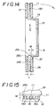
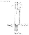
- Fig. 13 through 15 show still another embodiment of the invention, where a first rib 130 and a second rib 131 are alternately arranged.
- An inner end 141 of the second rib 131 is radially and outwardly recessed from the inner peripheral surfaces 15, 16 of the internal and external discs 11, 12. In other words, the inner end 141 of the second rib 131 does not extend to the inner peripheral surfaces 15, 16.
- an inner end 140 of the first rib 130 extends radially and inwardly from the inner peripheral surfaces 15, 16 of the internal and external discs 11, 12.
- the first rib 130 also has a broadened section 260 at and near the inner end 140. In the illustrated embodiment, the width of the broadened section 260 is greater than twice the width of the corresponding rib 130. However, the width of the broadened section 260 is not limited to the illustrated embodiment.
- a cooling air pathway 230 extends to the cylindrical member 19 and has a height greater than the height L of the ribs 130, 131 by M.
- the cooling efficiency of a ventilated-type disc rotor according to the invention is remarkably enhanced by the fact that the external and internal discs of the rotor are connected only by way of ribs to a cylindrical member which is by turn connected to a fitting plate to be fitted to the main body of a vehicle and a cooling air pathway is provided between the inner peripheral surface of the external disc and the outer peripheral surface of the cylindrical member or, in other words, that the external disc that can be heated to considerably high temperature is not directly connected to the cylindrical member that remains cool to minimized the thermal deformation of the discs, prevent formation of cracks in the disc and consequently prolong the service life of the ventilated-type disc rotor.
- the contact between the brake pad and the disc rotor is stabilized to enhance the performance of the brake and prevent generation of the phenomenon of brake jadder.
- the external and internal discs of a ventilated-type disc rotor according to the invention are connected to a cylindrical member only by way of ribs, which are axially made rather large and selectively provided with respective bulged reinforcement sections, the areas connecting the cylindrical member and the ribs are less liable to be thermal deformed and the areas connecting the discs, the ribs and the cylindrical members are less subjected to internal stress so that the contact between the brake pad and the disc rotor is stabilized to prevent generation of the phenomenon of brake jadder and consequently prolong the service life of the ventilated-type disc rotor.
- the above components of the disc rotor can be formed to a single piece by casting to reduce the number of steps and, at the same time, improve the strength of the disc rotor without involving difficulties in terms of casting.
Landscapes
- Engineering & Computer Science (AREA)
- General Engineering & Computer Science (AREA)
- Mechanical Engineering (AREA)
- Braking Arrangements (AREA)
Description
- This invention relates to a ventilated type disc rotor to be used for a braking system of a vehicle, the rotor comprising :
- an external disc,
- an internal disc,
- a flange to be fitted to a body of a vehicle,
- a cylindrical member continuously connected to an outer periphery of the flange,
- pathways for cooling air formed at an internal end of the cylindrical member between the external disc and the internal disc,
- radial ribs arranged between the external disc and the internal disc, the radial ribs being formed as one piece with the external disc, the internal disc and the flange, an axial thickness of the radial ribs being defined between the external disc and the internal disc, an inner end of each of the ribs radially extending from inner peripheral surfaces of the external and internal discs toward a centre of the external and internal discs, the inner end of each of the ribs being continuously connected to the internal end of the cylindrical member, and a gap formed between the inner peripheral surface of the external disc and an outer peripheral surface of the cylindrical member.
- DE-A-2,942,151 and DE-A-4,013,244 disclose rotors broadly in accordance with the foregoing description, although the former text is directed especially to the material by which the hub and a friction disc are joined together, and the latter text to the form of a collar on the hub where it meets the discs.
- In a conventional ventilated-type disc rotor such as the one as disclosed in Japanese Patent Laid-open No. 2-253020 and illustrated in Figures 16 and 17 of the accompanying drawings, a disc rotor which is generally designated by
reference numeral 1 in these Figures comprises aninternal disc 2 and anexternal disc 3 disposed in a face-to-face relationship with a number ofribs 4 radially arranged between the discs to providepathways 5 for cooling air defined by any two adjacent ribs so that the two discs are frictionally pressed against each other by way of a brake pad for braking the vehicle and the heat generated on the frictional surfaces of the discs is moved away from there with the air to cool the heated discs. - The
external disc 3 is connected at its inner periphery to acylindrical member 6, which is by turn connected to the outer periphery of afitting plate 7 that constitutes a flange to be secured to the vehicle main body. Said fittingplate 7 is provided with acentral bore 8, fittingholes 9 andauxiliary holes 10 arranged for making the operation of removing said disc rotor from the vehicle main body be carried out without difficulty. - A known ventilated-type disc rotor as described above is accompanied by a drawback of presenting a phenomenon of thermal deformation of the internal and
external discs discs - A large internal stress becomes present in the
external disc 3 as such a phenomenon takes place, leading to generation of radial cracks as typically indicated by C1 and C2 in Figures 19 and 20. Besides, as the discs are thermally deformed, the abutment (contact) of the brake pad and thedisc rotor 1 becomes unstable and a so-called brake judder phenomenon can occur in which the braking effect fluctuates. - It is therefore an object of the present invention to provide a ventilated-type disc rotor whose external and internal discs are free from thermal deformation when they are used for fierce braking operations and therefore free from cracks and which shows excellent cooling and braking efficiency under any conditions where the vehicle that carries it is driven.
- According to the present invention, the above object is achieved by providing a ventilated-type disc rotor as set out in the opening paragraph of the present specification, in which
- the internal end of the cylindrical member terminates prior to the external surface of the ribs, and
- the cooling air pathways extend toward the internal end of the cylindrical member so that the cooling air pathways have an axial length greater than the axial thickness of the ribs.
- With such an arrangement, since the frictional surfaces of the external and internal discs are connected only to the ribs and not to the cylindrical member which is fitted to the outer periphery of a flange to be fitted to the main body of a vehicle and a gap is provided between the inner periphery of the external disc and the outer peripheral surface of the cylindrical member, the overall cooling effect of the disc rotor is significantly improved and the thermal deformation of the discs can be minimized because the external disc and the cylindrical member are connected to each other only by way of the radially arranged thick ribs which normally remain cooler than the frictionally heated discs so that the internal stress of the external disc can be reduced and any possibility of occurrence of cracks can be eliminated to improve the abutment of the brake pad and the disc rotor and consequently their durability.
- Preferably, a bulge is formed on an outer peripheral surface of the cylindrical member.
- Advantageously, the radial ribs comprise first ribs and second ribs which are arranged alternately, with an inner end of each of the first ribs extending radially from inner peripheral surfaces of the internal and external discs toward a centre of the internal and external discs, the second ribs being recessed radially and outwardly from the inner peripheral surfaces of the external and internal discs, and the inner end of each of the first ribs being continuously connected to the internal end of the cylindrical member.
- Desired numbers of bulged reinforcement sections may be formed at and near the inner ends of the ribs. Said bulged reinforcement section may be a bridge continuously connecting the inner ends of adjacent ribs to each other in a space between the ends. Alternatively, a bulge may be formed on an outer peripheral surface of said cylindrical member. Instead, the said bulged reinforcement section may be a broadened section at and near the inner end of the rib. Or the said bulged reinforcement section may comprise a broadened section at and near the inner end of the rib and a bridge connecting adjacent broadened sections of a desired number of ribs. In a further modification, said bulged reinforcement section may be a bridge arranged in a gap between the inner peripheral surface of the external disc and the outer peripheral surface of the cylindrical member. Or a first rib and a second rib may be arranged alternately, an inner end of said first rib extending radially and inwardly from the inner peripheral surfaces of the external and internal discs, the second rib may be recessed radially and outwardly from the inner peripheral surfaces of the external and internal discs, said first rib may be provided with a broadened section at and near the inner end, and an air pathway may extend to the cylindrical member. Any of these forms of reinforcement may be realized without increasing the number of steps required for producing a ventilated-type disc rotor by casting.
- Examples of a ventilated-type disc rotor made in accordance with the present invention are illustrated in the accompanying drawings, in which :-
- Figure 1
- is a longitudinal sectional view of a preferred embodiment of the invention cut along the line A-A in Figure 2.
- Figure 2
- is a partially cut out plan view of the embodiment of Figure 1.
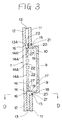
- Figure 3
- is a longitudinal sectional view of another preferred embodiment of the invention cut along the line C-C in Figure 4.
- Figure 4
- is a front view of the embodiment of Figure 3.
- Figure 5
- is a partial sectional view of the embodiment of Figure 3 cut along the line D-D in Figure 3.
- Figure 6
- is an enlarged partial view of the embodiment of Figure 3.
- Figure 7
- is a partial front view of still another embodiment of the invention.
- Fig. 8
- is a partial front view of a still another embodiment of the invention.
- Fig. 9
- is a partially cut out front view of a still another embodiment of the invention.
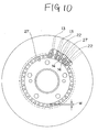
- Fig. 10
- is a partially cut out front view of a still another embodiment of the invention.
- Fig. 11
- is a partially cut out front view of a still another embodiment of the invention.
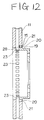
- Fig. 12
- is a longitudinal sectional view of a still another embodiment of the invention.
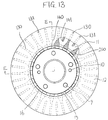
- Fig. 13
- is a partially cut out plan view of a still another embodiment of the invention.
- Fig. 14
- is a longitudinal sectional view of the embodiment of Fig. 13 cut along E-E line in Fig. 13.
- Fig. 15
- is a partial view of the embodiment of Fig. 13 as viewed in the direction of N indicated in Fig. 14.
- Fig. 16
- is a partially cut out plan view of a conventional disc rotor.
- Fig. 17
- is a longitudinal sectional view of the disc rotor in Fig. 16.
- Fig. 18
- is a longitudinal sectional view of the disc rotor of Fig. 16, schematically showing how its discs are thermally deformed.
- Fig. 19
- is a partial plan view of the internal disc of the disc rotor of Fig. 16, schematically showing how cracks are formed there and become apparent.
- Fig. 20
- is a partial plan view of the external disc of the disc rotor of Fig. 16, schematically showing how cracks are formed there and become apparent.
- Referring firstly to Figs. 1 and 2 showing a preferred embodiment of the invention, a ventilated-
type disc rotor 1 according to the invention comprises anexternal disc 11 and aninternal disc 12 juxtaposed in a face-to-face relationship and integrally formed with a number ofribs 13 arranged radially therebetween. For instance, theexternal disc 11, theinternal disc 12 and theribs 13 may be prepared into a single piece by casting. - An
inner end 14 of therib 13 radially extends from inner periphery surfaces 15, 16 of the external andinternal disc - The
inner end 14 of therib 13 is integrally connected to acylindrical member 19. Thecylindrical member 19 is integrally connected to anouter periphery 18 of afitting plate 17 which is used for securely fitting the ventilated-type disc rotor 1 to a body of a vehicle. In this illustrated embodiment, theexternal disc 11, theinternal disc 12, theribs 13, thecylindrical member 19 and the fitting plate or flange are integrally formed by casting to form them as one piece. Alternatively, however, the fitting flange may be welded and the remaining components may be cast and connected to the welded flange so as to form them as one piece. Still alternatively, any known arts may be utilized to produce an assembly of the discs, the ribs, the cylindrical member and the fitting flange as one piece. - A
gap 21 is formed between an innerperipheral surface 15 of theexternal disc 11 and an outerperipheral surface 20 of thecylindrical member 19. - The
fitting plate 17 is provided with acentral bore 8,fitting holes 9 andauxiliary holes 10 in a conventional manner. - Figs. 3 through 6 illustrate the second and third embodiments of the invention. In the second embodiment, a
bridge 22 of a bulgedreinforcement section 13A is formed with everyother space 14A between aninner end 14 of arib 13 and aninner end 14 theadjacent rib 13. In other words, thebridge 22 is alternately formed in thespace 14A. -
Pathways cylindrical body 19 between theexternal disc 11 and theinternal disc 12. Since theinner end 14 of theribs 13 is continuously connected to thecylindrical member 19 as illustrated in Figs. 3 and 5, thepathway 24 is narrowed by the thickness of therespective bridges 22 with theend 14 of therib 13. A portion connecting theinner end 14 of therib 13 and thecylindrical member 19 is reinforced by thebridges 22 or the bulgedreinforcement sections 13A. - Fig. 6 is an enlarged partial view of the portion continuously connecting the
inner end 14 of therib 13 and thecylindrical member 19. Abulge 19A is formed on an outer peripheral surface of thecylindrical member 19. Anarea 25 connecting thebulge 19A and anupper surface 13B of therib 13 is rounded with a relatively large radius of curvature. Thebulge 19A and the connectingarea 25 strengthen the connection of therib 13 and thecylindrical member 19. - In the embodiment illustrated in Fig. 3, the
bridge 22 is formed in everyother space 14A. Thebridge 22 may be arranged in everythird space 14A as illustrated in Fig. 7 or in everyspace 14A as illustrated in Fig. 8. The formation of thebridges 22 may be appropriately determined depending on the application of the ventilated-type disc rotor. - Fig. 9 illustrates another embodiment of the invention, where the
reinforcement sections 13A provided at and near the inner ends 14 of theribs 13 are realized in the form of broadenedsections 26 which are formed over the entire height of theribs 13 at and near their inner ends 14. - In the embodiments illustrated in Figs. 3 through 9, the
inner end 14 of therib 13 has a surface same as aninner surface 27 of thecylindrical member 19. Theinner end 14 may alternatively be radially and outwardly recessed from theinner surface 27 of thecylindrical member 19 by a distance W as illustrated in Fig. 10. Since theinner end 14 of the rib is 13 recessed from theinner surface 27 of thecylindrical member 19 by a distance W, when theinner surface 27 is finished by cutting, it can be avoided to interrupt the cutting operation caused by the construction that theinner end 14 of therib 13 is positioned in the same surface as theinner surface 27. - Fig. 11 shows still another embodiment of the invention. In this embodiment, the broadened
section 26 is provided at eachinner end 14 of therib 13. Thebridge 22 is arranged in everyother space 14A to continuously connect theinner end 14 of theribs 13 to the adjacent end. In addition, theinner end 14 is radially and outwardly recessed from the innerperipheral surface 27 of thecylindrical member 19 by a distance W. It will be easily understood that thebridges 22 may alternatively be realized in the form of those as illustrated in Fig. 5 or 6. - In the embodiment illustrated in Fig. 12, a
bridge 28 is formed in agap 21 between theinner surface 15 of theexternal disc 11 and theouter surface 20 of thecylindrical member 19 so as to prevent thepathway 25 for cooling air from narrowing. - Fig. 13 through 15 show still another embodiment of the invention, where a
first rib 130 and asecond rib 131 are alternately arranged. Aninner end 141 of thesecond rib 131 is radially and outwardly recessed from the innerperipheral surfaces external discs inner end 141 of thesecond rib 131 does not extend to the innerperipheral surfaces inner end 140 of thefirst rib 130 extends radially and inwardly from the innerperipheral surfaces external discs first rib 130 also has a broadenedsection 260 at and near theinner end 140. In the illustrated embodiment, the width of the broadenedsection 260 is greater than twice the width of thecorresponding rib 130. However, the width of the broadenedsection 260 is not limited to the illustrated embodiment. - In the embodiment of Figs. 13 through 15, a cooling
air pathway 230 extends to thecylindrical member 19 and has a height greater than the height L of theribs external disc 11 is put under stress as indicated by an arrow in Fig. 14, the stress can be effectively dispersed in alower end 231 of thecylindrical member 19 and an innerperipheral surface 232 of theexternal disc 11 to further enhance the strength of the disc. - As described above, the cooling efficiency of a ventilated-type disc rotor according to the invention is remarkably enhanced by the fact that the external and internal discs of the rotor are connected only by way of ribs to a cylindrical member which is by turn connected to a fitting plate to be fitted to the main body of a vehicle and a cooling air pathway is provided between the inner peripheral surface of the external disc and the outer peripheral surface of the cylindrical member or, in other words, that the external disc that can be heated to considerably high temperature is not directly connected to the cylindrical member that remains cool to minimized the thermal deformation of the discs, prevent formation of cracks in the disc and consequently prolong the service life of the ventilated-type disc rotor.
- Because of the minimized thermal deformation, the contact between the brake pad and the disc rotor is stabilized to enhance the performance of the brake and prevent generation of the phenomenon of brake jadder.
- In another aspect of the invention, since the external and internal discs of a ventilated-type disc rotor according to the invention are connected to a cylindrical member only by way of ribs, which are axially made rather large and selectively provided with respective bulged reinforcement sections, the areas connecting the cylindrical member and the ribs are less liable to be thermal deformed and the areas connecting the discs, the ribs and the cylindrical members are less subjected to internal stress so that the contact between the brake pad and the disc rotor is stabilized to prevent generation of the phenomenon of brake jadder and consequently prolong the service life of the ventilated-type disc rotor.
- In still another aspect of the invention, the above components of the disc rotor can be formed to a single piece by casting to reduce the number of steps and, at the same time, improve the strength of the disc rotor without involving difficulties in terms of casting.
Claims (4)
- A ventilated-type disc rotor comprising:an external disc (11),an internal disc (12),a flange (17) to be fitted to a part of a vehicle,a cylindrical member (19) continuously connected to an outer periphery (18) of the flange (17),pathways (23, 24, 230) for cooling air formed at an internal end (231) of the cylindrical member (19) between the external disc (11) and the internal disc (12),radial ribs (13) arranged between the external disc (11) and the internal disc (12), the radial ribs (13) being formed as one piece with the external disc (11), the internal disc (12) and the flange (17), an axial thickness (L) of the radial ribs (13) being defined between the external disc (11) and the internal disc (12), an inner end (14) of each of the ribs (13) radially extending from inner peripheral surfaces (15, 16) of the external and internal discs (11, 12) toward a centre of the external and internal discs (11, 12), the inner end (14) of each of the ribs (13) being continuously connected to the internal end (231) of the cylindrical member (19), anda gap (21) formed between the inner peripheral surface (15) of the external disc (11) and an outer peripheral surface (20) of the cylindrical member (19), characterised in that:the internal end (231) of the cylindrical member (19) terminates prior to the external surface (232) of the ribs (13), andthe cooling air pathways (230) extend toward the internal end (231) of the cylindrical member (19) so that the cooling air pathways (230) have an axial length (M+L) greater than the axial thickness (L) of the ribs (13).
- A ventilated-type disc rotor according to claim 1, characterised in that
a bulge (19A) is formed on an outer peripheral surface (20) of the cylindrical member (19). - A ventilated-type disc rotor comprising:an external disc (11),an internal disc (12),a flange (17) to be fitted to a part of a vehicle,a cylindrical member (19) continuously connected to an outer periphery (18) of the flange (17),pathways (23, 24, 230) for cooling air formed at an internal end (231) of the cylindrical member (19) between the external disc (11) and the internal disc (12),radial ribs (130, 131) arranged between the external disc (11) and the internal disc (12), the radial ribs (13, 131) being integrally formed as one piece with the external disc (11), the internal disc (12) and the flange (17), the radial ribs comprising first ribs (130) and second ribs (131) which are arranged alternately, an inner end (140) of each of the first ribs (130) radially extending from inner peripheral surfaces (15, 16) of the internal and external discs (11, 12) toward a centre of the internal and external discs (11, 12), the second ribs (131) being recessed radially and outwardly from the inner peripheral surfaces (15, 16) of the external and internal discs (11, 12), the inner end (140) of each of the first ribs (130) being continuously connected to the internal end (231) of the cylindrical member (19), anda gap (21) formed between the inner peripheral surface (15) of the external disc (11) and an outer peripheral surface (20) of the cylindrical member (19), characterised in thatthe internal end (231) of the cylindrical member (19) terminates prior to the external surface (232) of the ribs (130, 131), andthe cooling air pathways (230) extend toward the internal end (231) of the cylindrical member (19) so that the cooling air pathways (230) have an axial length (M+L) greater than the axial thickness (L) of the ribs (13).
- A ventilated-type disc rotor according to claim 3, characterised in that
a bulge (19A) is formed on the outer peripheral surface (20) of the cylindrical member (19).
Applications Claiming Priority (4)
| Application Number | Priority Date | Filing Date | Title |
|---|---|---|---|
| JP42373/91 | 1991-05-10 | ||
| JP4237391U JPH0589982U (en) | 1991-05-10 | 1991-05-10 | Ventilated type disc rotor |
| JP109954/91 | 1991-12-13 | ||
| JP10995491U JPH0550176U (en) | 1991-12-13 | 1991-12-13 | Ventilated type disc rotor |
Publications (2)
| Publication Number | Publication Date |
|---|---|
| EP0512853A1 EP0512853A1 (en) | 1992-11-11 |
| EP0512853B1 true EP0512853B1 (en) | 1996-08-21 |
Family
ID=26382041
Family Applications (1)
| Application Number | Title | Priority Date | Filing Date |
|---|---|---|---|
| EP92304159A Expired - Lifetime EP0512853B1 (en) | 1991-05-10 | 1992-05-08 | Ventilated-type disc rotor |
Country Status (3)
| Country | Link |
|---|---|
| US (1) | US5460249A (en) |
| EP (1) | EP0512853B1 (en) |
| DE (1) | DE69212887T2 (en) |
Families Citing this family (24)
| Publication number | Priority date | Publication date | Assignee | Title |
|---|---|---|---|---|
| IT230648Y1 (en) * | 1993-10-18 | 1999-06-09 | Brembo Spa | DISC OF A DISC BRAKE FOR VEHICLES IN GENERAL AND FOR HIGH PERFORMANCE VEHICLES IN PARTICULAR |
| DE4401845A1 (en) * | 1994-01-22 | 1995-07-27 | Teves Gmbh Alfred | Brake disc for disc brakes, pref. for vehicles |
| US5544726A (en) * | 1994-09-06 | 1996-08-13 | Ford Motor Company | Brake rotor with flow through ventilation |
| JPH09100854A (en) * | 1995-10-02 | 1997-04-15 | Honda Motor Co Ltd | Disc brake |
| JP3450158B2 (en) * | 1996-07-24 | 2003-09-22 | トヨタ自動車株式会社 | Disc rotor for disc brake |
| US6131707A (en) * | 1997-06-04 | 2000-10-17 | Kelsey-Hayes Company | Disc brake rotor and method for producing same |
| DE19822579A1 (en) * | 1997-06-12 | 1999-06-10 | Daimler Benz Ag | Automotive disc brake made of fiber-strengthened carbon or ceramic material |
| US6032769A (en) * | 1998-09-11 | 2000-03-07 | Hayes Lemmerz International, Inc. | Modular rotor |
| US6454058B1 (en) * | 2001-01-03 | 2002-09-24 | Delphi Technologies, Inc. | Disc brake rotor |
| EP1383109A1 (en) | 2002-07-17 | 2004-01-21 | STMicroelectronics N.V. | Method and device for wide band speech coding |
| GB0216749D0 (en) * | 2002-07-18 | 2002-08-28 | Meritor Heavy Vehicle Sys Ltd | Brake rotor |
| GB2393767B (en) * | 2002-10-02 | 2005-11-16 | Federal Mogul Products Inc | Disc brake rotors |
| DE10253451A1 (en) * | 2002-11-16 | 2004-05-27 | Bayerische Motoren Werke Ag | Compound brake disk, comprising center piece provided with openings for insertion of projections located at friction ring stub |
| US7219777B2 (en) * | 2003-04-11 | 2007-05-22 | Warren Lin | Reinforced brake rotor |
| GB2409886A (en) * | 2004-01-06 | 2005-07-13 | Surface Transforms Plc | Ventilated disc brake rotor |
| DE102004045327A1 (en) * | 2004-09-16 | 2006-03-23 | Georg Fischer Fahrzeugtechnik Ag | Brake disc arrangement for vehicle wheels |
| US8668058B2 (en) | 2005-03-30 | 2014-03-11 | Federal-Mogul Worldwide, Inc. | Vented disc brake rotor |
| US20070199778A1 (en) * | 2006-02-27 | 2007-08-30 | Lee Kwangjin M | Vented disc brake rotor |
| US7938378B2 (en) * | 2007-08-01 | 2011-05-10 | GM Global Technology Operations LLC | Damped product with insert and method of making the same |
| ATE522739T1 (en) * | 2008-04-01 | 2011-09-15 | Lucas Automotive Gmbh | BRAKE DISC AND DISC BRAKE |
| JP2009287621A (en) * | 2008-05-28 | 2009-12-10 | Hitachi Chem Co Ltd | Disc rotor for disc brake |
| US8763768B2 (en) * | 2008-12-08 | 2014-07-01 | Sheet Cast Technologies Gmbh | Brake disc and method for manufacturing a brake disc |
| KR101994113B1 (en) * | 2017-10-11 | 2019-07-01 | 경창산업주식회사 | Vented Brake Disc |
| FR3123100B1 (en) * | 2021-05-18 | 2023-07-14 | Psa Automobiles Sa | BRAKE DISC WITH VENTILATION FINS |
Family Cites Families (15)
| Publication number | Priority date | Publication date | Assignee | Title |
|---|---|---|---|---|
| US2368621A (en) * | 1942-12-30 | 1945-02-06 | American Steel Foundries | Brake rotor |
| US2423056A (en) * | 1945-03-01 | 1947-06-24 | Budd Co | Brake rotor |
| US2627325A (en) * | 1949-08-06 | 1953-02-03 | American Steel Foundries | Brake rotor |
| GB1587825A (en) * | 1976-12-11 | 1981-04-08 | Girling Ltd | Discs for disc brakes |
| DE2906589C2 (en) * | 1979-02-21 | 1986-10-23 | Knorr-Bremse AG, 8000 München | Brake disc for disc brake devices in rail vehicles |
| DE2942151A1 (en) * | 1979-10-18 | 1981-04-30 | Schmetz Industrieofenbau und Vakuum-Hartlöttechnik KG, 5750 Menden | Recessed hub for brake disc - has spaced teeth on periphery to which friction rings are brazed on opposite sides |
| JPH068312B2 (en) * | 1981-01-29 | 1994-02-02 | 藤沢薬品工業株式会社 | New peptide manufacturing method |
| JPS5849545A (en) * | 1981-09-18 | 1983-03-23 | Takaoka Kogyo Kk | Disc-brake-rotor and manufacturing method thereof |
| JPS58134241A (en) * | 1982-02-05 | 1983-08-10 | Sunstar Kinzoku Kk | Manufacture of plate for disk brake |
| DE3432374A1 (en) * | 1984-09-03 | 1986-04-30 | Knorr-Bremse AG, 8000 München | SHAFT BRAKE DISC, IN PARTICULAR FOR DISC BRAKES OF RAIL VEHICLES |
| DE3811222A1 (en) * | 1988-04-02 | 1989-10-12 | Bayerische Motoren Werke Ag | Brake disc for disc brakes |
| US5161652A (en) * | 1988-10-18 | 1992-11-10 | Honda Giken Kogyo Kabushiki Kaisha | Ventilated disk brake rotor |
| JPH02107834A (en) * | 1988-10-18 | 1990-04-19 | Honda Motor Co Ltd | ventilated brake rotor |
| JPH02253020A (en) * | 1989-03-27 | 1990-10-11 | Fuji Heavy Ind Ltd | Brake disc preventing thermal deformation |
| DE4013244A1 (en) * | 1990-04-26 | 1991-10-31 | Buderus Kundenguss | ONE-PIECE AIR-COOLED BRAKE DISC |
-
1992
- 1992-05-08 EP EP92304159A patent/EP0512853B1/en not_active Expired - Lifetime
- 1992-05-08 DE DE69212887T patent/DE69212887T2/en not_active Expired - Fee Related
-
1994
- 1994-07-28 US US08/281,533 patent/US5460249A/en not_active Expired - Fee Related
Also Published As
| Publication number | Publication date |
|---|---|
| DE69212887T2 (en) | 1997-01-16 |
| DE69212887D1 (en) | 1996-09-26 |
| EP0512853A1 (en) | 1992-11-11 |
| US5460249A (en) | 1995-10-24 |
Similar Documents
| Publication | Publication Date | Title |
|---|---|---|
| EP0512853A1 (en) | Ventilated-type disc rotor | |
| EP0082786B1 (en) | A rotor for a disc brake assembly | |
| US6164423A (en) | Vented rotor for caliper disc brakes and the like | |
| US4177883A (en) | Discs for disc brakes | |
| US6098764A (en) | Shaft brake disk for rail vehicle disk brake systems and method of making same | |
| US6367599B2 (en) | Ventilated disc | |
| US20010040077A1 (en) | Brake rotor having an array of grooves formed thereon | |
| JP2002524700A (en) | Brake disc and corresponding axle hub | |
| EP1228322B1 (en) | Brake disc for a vehicle disc brake | |
| US20250224008A1 (en) | Brake disc | |
| US6241053B1 (en) | Ventilated disc brake rotor | |
| US5137123A (en) | Brake disk | |
| EP0630447A1 (en) | Shielded vehicle brake. | |
| GB2144186A (en) | Disc for disc brake | |
| US9488238B2 (en) | Composite rotor | |
| US20100025169A1 (en) | Brake disk for a disk brake | |
| JP4348132B2 (en) | Brake rotor | |
| EP1379794B1 (en) | Bell for braking disc and disc for a disc brake | |
| GB2172676A (en) | Improvements relating to discs for disc brakes | |
| US5320201A (en) | Truck brake drum with increased cooling | |
| EP0906521A1 (en) | Disc brake rotor | |
| WO1998050837A1 (en) | Solid finned rotor for caliper disc brakes and the like | |
| GB2307960A (en) | A rotor for a disc brake | |
| GB2211253A (en) | Ventilated brake disc | |
| JP2556878Y2 (en) | Ventilated type disk rotor |
Legal Events
| Date | Code | Title | Description |
|---|---|---|---|
| PUAI | Public reference made under article 153(3) epc to a published international application that has entered the european phase |
Free format text: ORIGINAL CODE: 0009012 |
|
| AK | Designated contracting states |
Kind code of ref document: A1 Designated state(s): DE FR GB IT |
|
| 17P | Request for examination filed |
Effective date: 19930329 |
|
| 17Q | First examination report despatched |
Effective date: 19940428 |
|
| GRAH | Despatch of communication of intention to grant a patent |
Free format text: ORIGINAL CODE: EPIDOS IGRA |
|
| GRAH | Despatch of communication of intention to grant a patent |
Free format text: ORIGINAL CODE: EPIDOS IGRA |
|
| GRAA | (expected) grant |
Free format text: ORIGINAL CODE: 0009210 |
|
| AK | Designated contracting states |
Kind code of ref document: B1 Designated state(s): DE FR GB IT |
|
| REF | Corresponds to: |
Ref document number: 69212887 Country of ref document: DE Date of ref document: 19960926 |
|
| ET | Fr: translation filed | ||
| ITF | It: translation for a ep patent filed | ||
| PLBE | No opposition filed within time limit |
Free format text: ORIGINAL CODE: 0009261 |
|
| STAA | Information on the status of an ep patent application or granted ep patent |
Free format text: STATUS: NO OPPOSITION FILED WITHIN TIME LIMIT |
|
| 26N | No opposition filed | ||
| PGFP | Annual fee paid to national office [announced via postgrant information from national office to epo] |
Ref country code: GB Payment date: 20000511 Year of fee payment: 9 |
|
| PGFP | Annual fee paid to national office [announced via postgrant information from national office to epo] |
Ref country code: DE Payment date: 20000524 Year of fee payment: 9 |
|
| PGFP | Annual fee paid to national office [announced via postgrant information from national office to epo] |
Ref country code: FR Payment date: 20000531 Year of fee payment: 9 |
|
| PG25 | Lapsed in a contracting state [announced via postgrant information from national office to epo] |
Ref country code: GB Free format text: LAPSE BECAUSE OF NON-PAYMENT OF DUE FEES Effective date: 20010508 |
|
| GBPC | Gb: european patent ceased through non-payment of renewal fee |
Effective date: 20010508 |
|
| PG25 | Lapsed in a contracting state [announced via postgrant information from national office to epo] |
Ref country code: FR Free format text: LAPSE BECAUSE OF NON-PAYMENT OF DUE FEES Effective date: 20020131 |
|
| PG25 | Lapsed in a contracting state [announced via postgrant information from national office to epo] |
Ref country code: DE Free format text: LAPSE BECAUSE OF NON-PAYMENT OF DUE FEES Effective date: 20020301 |
|
| PG25 | Lapsed in a contracting state [announced via postgrant information from national office to epo] |
Ref country code: IT Free format text: LAPSE BECAUSE OF NON-PAYMENT OF DUE FEES Effective date: 20050508 |