EP0512602A1 - Mowing machine - Google Patents
Mowing machine Download PDFInfo
- Publication number
- EP0512602A1 EP0512602A1 EP92201152A EP92201152A EP0512602A1 EP 0512602 A1 EP0512602 A1 EP 0512602A1 EP 92201152 A EP92201152 A EP 92201152A EP 92201152 A EP92201152 A EP 92201152A EP 0512602 A1 EP0512602 A1 EP 0512602A1
- Authority
- EP
- European Patent Office
- Prior art keywords
- connecting piece
- coupling member
- frame beam
- setting
- mowing machine
- Prior art date
- Legal status (The legal status is an assumption and is not a legal conclusion. Google has not performed a legal analysis and makes no representation as to the accuracy of the status listed.)
- Granted
Links
- 230000008878 coupling Effects 0.000 claims abstract description 32
- 238000010168 coupling process Methods 0.000 claims abstract description 32
- 238000005859 coupling reaction Methods 0.000 claims abstract description 32
- 239000012530 fluid Substances 0.000 claims description 8
- 238000010276 construction Methods 0.000 description 5
- 230000002035 prolonged effect Effects 0.000 description 1
- 238000007789 sealing Methods 0.000 description 1
Images

Classifications
-
- A—HUMAN NECESSITIES
- A01—AGRICULTURE; FORESTRY; ANIMAL HUSBANDRY; HUNTING; TRAPPING; FISHING
- A01B—SOIL WORKING IN AGRICULTURE OR FORESTRY; PARTS, DETAILS, OR ACCESSORIES OF AGRICULTURAL MACHINES OR IMPLEMENTS, IN GENERAL
- A01B73/00—Means or arrangements to facilitate transportation of agricultural machines or implements, e.g. folding frames to reduce overall width
-
- A—HUMAN NECESSITIES
- A01—AGRICULTURE; FORESTRY; ANIMAL HUSBANDRY; HUNTING; TRAPPING; FISHING
- A01B—SOIL WORKING IN AGRICULTURE OR FORESTRY; PARTS, DETAILS, OR ACCESSORIES OF AGRICULTURAL MACHINES OR IMPLEMENTS, IN GENERAL
- A01B61/00—Devices for, or parts of, agricultural machines or implements for preventing overstrain
- A01B61/02—Devices for, or parts of, agricultural machines or implements for preventing overstrain of the coupling devices between tractor and machine
-
- A—HUMAN NECESSITIES
- A01—AGRICULTURE; FORESTRY; ANIMAL HUSBANDRY; HUNTING; TRAPPING; FISHING
- A01D—HARVESTING; MOWING
- A01D75/00—Accessories for harvesters or mowers
- A01D75/18—Safety devices for parts of the machines
- A01D75/185—Avoiding collisions with obstacles
Definitions
- the invention relates to a mowing machine provided with a frame with a coupling member to be coupled to a tractor or the like, with a connecting piece which is pivotable with respect to said coupling member about an upwardly extending pivot pin located near one end of said coupling member, as well as with a frame beam carrying a plurality of mowing means, which is rotatable with respect to the coupling member about an upwardly extending pivot pin located near the end of the coupling member remote from the end of the coupling member adjoining the connecting piece, whilst means are provided that do not allow the frame beam to pivot about a pivot pin before the force exerted on the frame beam exceeds a predetermined value.
- Such mowing machines are generally provided with a mechanical locking mechanism comprising a spring-loaded locking pin or the like, whereby said locking pin, when a force exerted on the frame beam exceeds a predetermined value, can move out against the spring force of the spring so as to enable a pivotal motion of the frame beam carrying the mowing means opposite the direction of movement during operation.
- a mechanical locking mechanism comprising a spring-loaded locking pin or the like, whereby said locking pin, when a force exerted on the frame beam exceeds a predetermined value, can move out against the spring force of the spring so as to enable a pivotal motion of the frame beam carrying the mowing means opposite the direction of movement during operation.
- the object of the invention is to obtain a mowing machine of the above kind, wherein the drawbacks of the known constructions can be avoided and an effective moving out of the frame beam carrying the mowing means during operation can be ensured at all times when the forces exerted on said frame beam or on the connecting piece connecting the frame beam to the coupling member, as the case may be, exceed a certain value.
- the construction will be highly insensitive to rusting and/or fouling, so that even after prolonged use of the mowing machine the frame beam carrying the mowing means will still move out at the intended force, whereby the connecting piece and/or the frame beam may slightly pivot backwards when the force exerted on the connecting piece and/or the frame beam exceeds a predetermined value, which is already sufficient in many cases in order to keep the forces exerted on the carrying part and/or the coupling member within allowable limits, whilst generally the frame beam will not pivot further backwards before a larger force is exerted on the frame beam.
- a further advantage of the construction according to the invention is that, after the mowing machine has possibly been lifted from the ground, the coupling member and the frame beam can be pivoted back to the position suitable for operation by means of the hydraulic setting cylinders, without the tractor driver having to leave his position on the tractor, whilst the setting cylinders may also be used to shift the mowing machine from an operating position into a transport position, and conversely.
- Figure 1 is a diagrammatic plan view of a mowing machine according to the invention, wherein the full lines illustrate the position suitable for operation and the dotted lines indicate a transport position and a position in which the mowing machine is partially pivoted backwards.
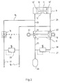
- Figure 2 diagrammatically shows the arrangement of the hydraulic cylinders that form part of the mowing machine according to the invention.
- the mowing machine comprises a coupling member 1, which is to be coupled to an agricultural implement or the like, said coupling member in the illustrated embodiment being constructed so as to be attached to a three-point hitch of a tractor or the like.
- One end of a connecting piece 2 is coupled to said coupling member 1 in such a manner, that said connecting piece is pivotable with respect to the coupling member 1 about a pivot pin 3 extending at least substantially vertically during normal operation.
- a frame beam 5 is attached to the end of the connecting piece 2 remote from the pivot pin 3, by means of a pivot pin 4 extending parallel to the pivot pin 3.
- the frame beam 5 for example supports, in a manner known per se, a plurality of mowing means or mowing drums arranged in side-by-side relationship in a row, which are rotatable about upwardly extending axes of rotation and which are arranged under a protecting plate 6 secured to the frame beam 5, when seen in Figure 1.
- Said mowing means can be driven from the power take-off shaft of the tractor, via driving means located in a casing 7 extending parallel to the connecting piece or frame beam 2.
- the construction of such a mowing machine is quite common and need not be further explained or illustrated, therefore.
- a hydraulic setting cylinder 8 is provided between the coupling member 1 and the connecting piece 2, spaced from the pivot pin 3 by some distance. Furthermore a hydraulic setting cylinder 9 is secured to the frame beam 5.
- a piston rod 10 is accommodated in the setting cylinder 9, said piston rod at both ends being provided with sealing rings 10' co-operating with the inner wall of the cylinder 9.
- a central portion of the piston rod 10 forms a rack 11, whilst near said rack 11 a hole 12 is provided in the wall of the cylinder 9.
- the part of the rack 11 located near the hole 12 is in engagement with a gear (not shown), which is provided in a gear box 13 secured to the connecting piece 2.
- Said gear co-operating with the rack 11 is arranged in such a manner that the central axis of said gear coincides with the central axis of the pivot pin 4, whilst the gear has a fixed position with respect to the connecting piece 2.
- Lines 14 and 15 respectively are connected to the ends of the setting cylinder 9.
- Said line 14 is in communication with a line 17 via a non-return valve mechanism 16, which line 17 can be coupled to the hydraulic circuit of a vehicle, such as a tractor, propelling the mowing machine during operation.
- the setting cylinder 8 is provided with an attaching eye 18, by means of which the setting cylinder can be attached to the coupling member 1 or the connecting piece 2.
- a piston rod 19 located inside the setting cylinder 8 is at one end provided with a piston 20 secured to said piston rod 19.
- the end of the piston rod 19 remote from the piston 20 is passed through a stuffing box 21, whilst at its end projecting from the setting cylinder 8 said piston rod is provided with an attaching eye 22, for attachment to the connecting piece 2 or the coupling member 1.
- the setting cylinder 8 is illustrated in the position which it will at least substantially occupy during normal operation of the mowing machine, i.e. with the piston rod 19 and the piston 20 attached thereto moved into the setting cylinder 8 as far as possible.
- the end of the setting cylinder 8 located near the stuffing box 21 is connected to the line 14 via a line 23.
- the line 15 is connected to the interior of the setting cylinder 8, via a line 24, in a point located at the side of the piston 20 remote from the piston rod 19. Furthermore the free end of the line 15 may also be connected to the hydraulic circuit of a tractor or the like vehicle propelling the mowing machine during operation.
- the interior of the setting cylinder 8 is furthermore in communication with a connector 25, via which the interior of the setting cylinder 8 is in communication with an accumulator 26, in which a pressure of e.g. 100 - 120 bar prevails during normal operation. Furthermore an adjustable pressure relief valve 27 is connected to the connector 25, which pressure relief valve shuts off the connection between the connector 25 and one end of a line 28 during normal operation.
- the end of the line 28 remote from the connecting piece 25 is in turn in communication with the interior of the setting cylinder 8, at a point located at the side of the piston 20 remote from the piston rod 19, near the same end of the setting cylinder 8 as to which the line 24 is connected.
- the pressure relief valve 27 opens at a pressure of e.g. ⁇ 180 bar.
- Another valve mechanism 29 is provided between the lines 17 and 15, via which fluid can be passed from the line 17 to the line 15 and which allows fluid to flow back into the line 15 when the pressure in the line 17 exceeds a pressure of e.g. 120 bar.
- a line 30 is provided between the valve mechanism 16 and the line 15, whose purpose will be described in more detail hereafter.
- the pressure in the setting cylinder 8 may become higher than the pressure prevailing in the accumulator 26, as a result of which the setting cylinder 8 will move out, whilst squeezing fluid from the setting cylinder to the accumulator. It will be apparent that consequently the connecting piece 2 and the frame beam 5 carried by the connecting piece can pivot backwards about the shaft 3, opposite the direction of movement.
- the setting cylinder 8 can return to its original position again, because the pressurized fluid flows back from the accumulator 26 into the setting cylinder 8.
- pressurized oil may be supplied, by operating a suitable valve provided on the vehicle in question, to the line 17 of the hydraulic circuit on the mowing machine illustrated in Figure 2. Said pressurized oil will be supplied, via the valve 16 and the lines 14 and 23, to the left-hand ends, when seen in Figure 2, of the setting cylinders 9 and 8, as a result of which the piston rods 10 and 19 will be moved towards the right again, when seen in Figure 2, to the positions illustrated in Figure 2.
- the fluid present in the right-hand portions of the cylinders 8 and 9 in question can flow back to the hydraulic circuit of the tractor via the line 15.
- valve 27 will close automatically and the pressure in the accumulator 26 will return to the desired value of 100 - 120 bar, which is ensured by the setting of the valve 29, which will discharge fluid supplied via the line 17 to the line 15 when the desired pressure in the accumulator 26 is reached.
- the above-described setting cylinders 8 and 9 may also be used in order to put the mowing machine in its transport position, in which, as indicated in Figure 1, the frame beam 5 carrying the mowing means is pivoted clockwise through ⁇ 180° with respect to the connecting piece 2, from the normal operating position illustrated in full lines to the transport position illustrated in dotted lines, in which the frame beam 5 carring the mowing means is located at least substantially entirely behind the tractor or the like, when seen in the intended direction of movement.
- pressurized oil is supplied to the line 15 by suitably controlling a valve, which forms part of the hydraulic circuit of the tractor or the like. Said pressurized oil is therefore supplied to the right-hand ends, when seen in Figure 2, of the setting cylinders 8 and 9, as a result of which the piston rods 19 and 10 will be moved towards the left, when seen in Figure 2. Consequently the connecting piece 2 will be pivoted clockwise, when seen in Figure 1, about the pivot pin 3, whilst furthermore the frame beam 5 will be pivoted through ⁇ 180° with respect to the connecting piece 2, when seen in Figure 1, about the pivot pin 4.
- the oil which is squeezed out of the left-hand ends of the setting cylinders 9 and 8, when seen in Figure 2 can flow back to the hydraulic circuit of the tractor via the valve mechanism 16, which is opened by the pressure in the line 30, through the lines 14, 23 and 17.
- pressurized oil may again be supplied to the line 17, as described above, as a result of which the piston rods 10 and 19 will return to the position shown in Figure 2.
Landscapes
- Life Sciences & Earth Sciences (AREA)
- Environmental Sciences (AREA)
- Engineering & Computer Science (AREA)
- Mechanical Engineering (AREA)
- Soil Sciences (AREA)
- Harvester Elements (AREA)
Abstract
Description
- The invention relates to a mowing machine provided with a frame with a coupling member to be coupled to a tractor or the like, with a connecting piece which is pivotable with respect to said coupling member about an upwardly extending pivot pin located near one end of said coupling member, as well as with a frame beam carrying a plurality of mowing means, which is rotatable with respect to the coupling member about an upwardly extending pivot pin located near the end of the coupling member remote from the end of the coupling member adjoining the connecting piece, whilst means are provided that do not allow the frame beam to pivot about a pivot pin before the force exerted on the frame beam exceeds a predetermined value.
- Such mowing machines are generally provided with a mechanical locking mechanism comprising a spring-loaded locking pin or the like, whereby said locking pin, when a force exerted on the frame beam exceeds a predetermined value, can move out against the spring force of the spring so as to enable a pivotal motion of the frame beam carrying the mowing means opposite the direction of movement during operation.
- Such mechanical locking means are exposed to rusting and fouling, however, which will affect the intended operation of the locking means.
- The object of the invention is to obtain a mowing machine of the above kind, wherein the drawbacks of the known constructions can be avoided and an effective moving out of the frame beam carrying the mowing means during operation can be ensured at all times when the forces exerted on said frame beam or on the connecting piece connecting the frame beam to the coupling member, as the case may be, exceed a certain value.
- According to the invention this can be achieved in that a hydraulic setting cylinder is provided between the coupling member and the connecting piece as well as between the connecting piece and the frame beam, said setting cylinders being under pressure during normal operation and being incorporated in a hydraulic circuit, in such a manner that when a predetermined force on the frame beam and/or the connecting piece is exceeded, a pivotal motion occurs between the coupling member and the connecting piece and/or between the connecting piece and the frame beam.
- Since hydraulic setting cylinders are used the construction will be highly insensitive to rusting and/or fouling, so that even after prolonged use of the mowing machine the frame beam carrying the mowing means will still move out at the intended force, whereby the connecting piece and/or the frame beam may slightly pivot backwards when the force exerted on the connecting piece and/or the frame beam exceeds a predetermined value, which is already sufficient in many cases in order to keep the forces exerted on the carrying part and/or the coupling member within allowable limits, whilst generally the frame beam will not pivot further backwards before a larger force is exerted on the frame beam.
- A further advantage of the construction according to the invention is that, after the mowing machine has possibly been lifted from the ground, the coupling member and the frame beam can be pivoted back to the position suitable for operation by means of the hydraulic setting cylinders, without the tractor driver having to leave his position on the tractor, whilst the setting cylinders may also be used to shift the mowing machine from an operating position into a transport position, and conversely.
- The invention will be explained in more detail hereafter with reference to an embodiment of the construction according to the invention illustrated in the accompanying Figures.
- Figure 1 is a diagrammatic plan view of a mowing machine according to the invention, wherein the full lines illustrate the position suitable for operation and the dotted lines indicate a transport position and a position in which the mowing machine is partially pivoted backwards.
- Figure 2 diagrammatically shows the arrangement of the hydraulic cylinders that form part of the mowing machine according to the invention.
- As is diagrammatically shown in Figure 1 the mowing machine comprises a coupling member 1, which is to be coupled to an agricultural implement or the like, said coupling member in the illustrated embodiment being constructed so as to be attached to a three-point hitch of a tractor or the like.
- One end of a connecting
piece 2 is coupled to said coupling member 1 in such a manner, that said connecting piece is pivotable with respect to the coupling member 1 about apivot pin 3 extending at least substantially vertically during normal operation. - A
frame beam 5 is attached to the end of the connectingpiece 2 remote from thepivot pin 3, by means of apivot pin 4 extending parallel to thepivot pin 3. Theframe beam 5 for example supports, in a manner known per se, a plurality of mowing means or mowing drums arranged in side-by-side relationship in a row, which are rotatable about upwardly extending axes of rotation and which are arranged under a protectingplate 6 secured to theframe beam 5, when seen in Figure 1. Said mowing means can be driven from the power take-off shaft of the tractor, via driving means located in acasing 7 extending parallel to the connecting piece orframe beam 2. The construction of such a mowing machine is quite common and need not be further explained or illustrated, therefore. - A
hydraulic setting cylinder 8 is provided between the coupling member 1 and the connectingpiece 2, spaced from thepivot pin 3 by some distance. Furthermore ahydraulic setting cylinder 9 is secured to theframe beam 5. As is illustrated in Figure 2 apiston rod 10 is accommodated in thesetting cylinder 9, said piston rod at both ends being provided with sealing rings 10' co-operating with the inner wall of thecylinder 9. A central portion of thepiston rod 10 forms arack 11, whilst near said rack 11 ahole 12 is provided in the wall of thecylinder 9. The part of therack 11 located near thehole 12 is in engagement with a gear (not shown), which is provided in agear box 13 secured to the connectingpiece 2. Said gear co-operating with therack 11 is arranged in such a manner that the central axis of said gear coincides with the central axis of thepivot pin 4, whilst the gear has a fixed position with respect to the connectingpiece 2. -
Lines setting cylinder 9. - Said
line 14 is in communication with a line 17 via anon-return valve mechanism 16, which line 17 can be coupled to the hydraulic circuit of a vehicle, such as a tractor, propelling the mowing machine during operation. - As is furthermore shown in Figure 1, the
setting cylinder 8 is provided with an attachingeye 18, by means of which the setting cylinder can be attached to the coupling member 1 or the connectingpiece 2. - A
piston rod 19 located inside thesetting cylinder 8 is at one end provided with apiston 20 secured to saidpiston rod 19. The end of thepiston rod 19 remote from thepiston 20 is passed through astuffing box 21, whilst at its end projecting from thesetting cylinder 8 said piston rod is provided with an attachingeye 22, for attachment to the connectingpiece 2 or the coupling member 1. - The
setting cylinder 8 is illustrated in the position which it will at least substantially occupy during normal operation of the mowing machine, i.e. with thepiston rod 19 and thepiston 20 attached thereto moved into thesetting cylinder 8 as far as possible. - The end of the
setting cylinder 8 located near thestuffing box 21 is connected to theline 14 via aline 23. Theline 15 is connected to the interior of thesetting cylinder 8, via aline 24, in a point located at the side of thepiston 20 remote from thepiston rod 19. Furthermore the free end of theline 15 may also be connected to the hydraulic circuit of a tractor or the like vehicle propelling the mowing machine during operation. - At one end located near the
stuffing box 21 the interior of thesetting cylinder 8 is furthermore in communication with aconnector 25, via which the interior of thesetting cylinder 8 is in communication with anaccumulator 26, in which a pressure of e.g. 100 - 120 bar prevails during normal operation. Furthermore an adjustablepressure relief valve 27 is connected to theconnector 25, which pressure relief valve shuts off the connection between theconnector 25 and one end of aline 28 during normal operation. The end of theline 28 remote from the connectingpiece 25 is in turn in communication with the interior of thesetting cylinder 8, at a point located at the side of thepiston 20 remote from thepiston rod 19, near the same end of thesetting cylinder 8 as to which theline 24 is connected. - The
pressure relief valve 27 opens at a pressure of e.g. ± 180 bar. Anothervalve mechanism 29 is provided between thelines 17 and 15, via which fluid can be passed from the line 17 to theline 15 and which allows fluid to flow back into theline 15 when the pressure in the line 17 exceeds a pressure of e.g. 120 bar. - Furthermore a
line 30 is provided between thevalve mechanism 16 and theline 15, whose purpose will be described in more detail hereafter. - During normal operation, when both the connecting
piece 2 and theframe beam 5 carrying the mowing means extend transversely to the intended direction of movement according to the arrow A, thepiston rods setting cylinders setting cylinder 8 as well as in the interior of the left-hand part, when seen in Figure 2, of thesetting cylinder 9, via thelines accumulator 26 will prevail, i.e. a pressure of e.g. 100 - 120 bar. - When, for example, the forces exerted on the frame beam and/or the connecting
piece 2 via the mowing means exceed a predetermined value, the pressure in thesetting cylinder 8 may become higher than the pressure prevailing in theaccumulator 26, as a result of which thesetting cylinder 8 will move out, whilst squeezing fluid from the setting cylinder to the accumulator. It will be apparent that consequently the connectingpiece 2 and theframe beam 5 carried by the connecting piece can pivot backwards about theshaft 3, opposite the direction of movement. When the forces exerted on theframe beam 5 or theframe beam 2, as the case may be, decrease again thesetting cylinder 8 can return to its original position again, because the pressurized fluid flows back from theaccumulator 26 into thesetting cylinder 8. - When the force exerted on the
frame beam 5 and/or theframe beam 2 further increases, however, it is possible that at a given moment the pressure in the interior of thesetting cylinders pressure relief valve 27 opens. In that case the fluid can escape from the left-hand part of thesetting cylinder 9 via thelines setting cylinder 8, theopen valve 27, theline 28, theline 24 and theline 15, in order to flow back into the right-hand part, when seen in Figure 2, of thesetting cylinder 9 via theline 15. - In that case the
piston rod 10 and therack 11 integral therewith will move towards the left, when seen in Figure 2. It will be apparent, that therack 11 will also move with respect to the gear fixed to the connectingpiece 2 and being accommodated in thegear box 13 thereby, all this in such a manner that theframe beam 5 will pivot backwards about thepivot pin 14 with respect to the connectingpiece 2, in clockwise direction, when seen in Figure 1. - After the obstacle that caused the allowable force exerted on the
frame beam 5 and/or the connectingpiece 2 to be exceeded has been removed and/or the mowing machine has been lifted by means of the three-point hitch of the vehicle propelling the mowing machine, the machine may be returned to the position suitable for operation. For this purpose pressurized oil may be supplied, by operating a suitable valve provided on the vehicle in question, to the line 17 of the hydraulic circuit on the mowing machine illustrated in Figure 2. Said pressurized oil will be supplied, via thevalve 16 and thelines setting cylinders piston rods cylinders line 15. - The
valve 27 will close automatically and the pressure in theaccumulator 26 will return to the desired value of 100 - 120 bar, which is ensured by the setting of thevalve 29, which will discharge fluid supplied via the line 17 to theline 15 when the desired pressure in theaccumulator 26 is reached. - The above-described
setting cylinders frame beam 5 carrying the mowing means is pivoted clockwise through ± 180° with respect to the connectingpiece 2, from the normal operating position illustrated in full lines to the transport position illustrated in dotted lines, in which theframe beam 5 carring the mowing means is located at least substantially entirely behind the tractor or the like, when seen in the intended direction of movement. - In order to put the mowing machine in its transport position pressurized oil is supplied to the
line 15 by suitably controlling a valve, which forms part of the hydraulic circuit of the tractor or the like. Said pressurized oil is therefore supplied to the right-hand ends, when seen in Figure 2, of thesetting cylinders piston rods piece 2 will be pivoted clockwise, when seen in Figure 1, about thepivot pin 3, whilst furthermore theframe beam 5 will be pivoted through ± 180° with respect to the connectingpiece 2, when seen in Figure 1, about thepivot pin 4. The oil which is squeezed out of the left-hand ends of thesetting cylinders valve mechanism 16, which is opened by the pressure in theline 30, through thelines - When the pressure in the
line 15 exceeds a predetermined value, oil can escape from theline 15 to the line 17 via thevalve mechanism 29, and flow back from said line 17 to the hydraulic circuit of the tractor. - In order to return the mowing machine from the transport position to the position suitable for operation pressurized oil may again be supplied to the line 17, as described above, as a result of which the piston rods 10 and 19 will return to the position shown in Figure 2.
Claims (6)
- A mowing machine provided with a frame with a coupling member to be coupled to a tractor or the like, with a connecting piece which is pivotable with respect to said coupling member about an upwardly extending pivot pin located near one end of said coupling member, as well as with a frame beam carrying a plurality of mowing means, which is rotatable with respect to the coupling member about an upwardly extending pivot pin located near the end of the coupling member remote from the end of the coupling member adjoining the connecting piece, whilst means are provided that do not allow the frame beam to pivot about a pivot pin before the force exerted on the frame beam exceeds a predetermined value, characterized in that a hydraulic setting cylinder is provided between the coupling member and the connecting piece as well as between the connecting piece and the frame beam, said setting cylinders being under pressure during normal operation and being incorporated in a hydraulic circuit, in such a manner that when a predetermined force on the frame beam and/or the connecting piece is exceeded, a pivotal motion occurs between the coupling member and the connecting piece and/or between the connecting piece and the frame beam.
- A mowing machine according to claim 1, characterized in that the ends of the setting cylinders, towards which the piston rods or pistons located in the setting cylinders in question move when the connecting piece and/or the carrying part are moved from their normal operating position, are interconnected by means of a line and are furthermore connected to an accumulator, in which a predetermined pressure is maintained during operation.
- A mowing machine according to claim 2, characterized in that the two other ends of the setting cylinders are likewise interconnected, whilst between the two ends of one of the setting cylinders a bypass is provided, in which a pressure relief valve is provided, which, when a predetermined pressure is exceeded near the end of the setting cylinder in question, towards which a piston located in the setting cylinder moves when the connecting piece and/or the carrying part are pivoted from the operating positon, places the two ends of the setting cylinder in question in open communication with each other.
- A mowing machine according to any one of the preceding claims, characterized in that the lines connected to the ends of the setting cylinders may be connected to the hydraulic circuit of a tractor or the like propelling the mowing machine during operation.
- A mowing machine according to claim 4, characterized in that a valve mechanism is provided in the line which is connected to the two ends of the setting cylinders towards which the pistons or piston rods located in the cylinders in question move when the connecting piece and/or the carrying part are moved from their normal operating position, which valve mechanism only allows fluid to pass from the hydraulic circuit of the tractor in the direction of the setting cylinders.
- A mowing machine according to any one of the preceding claims, characterized in that a piston rod is accommodated in the setting cylinder which is provided between the carrying part and the connecting piece and is mounted on said carrying part, said piston rod being connected to a rack, which is in engagement with a gear fixed to the connecting piece, the central axis of said gear coinciding with the pivot pin about which the carrying part can pivot with respect to the connecting piece.
Applications Claiming Priority (2)
| Application Number | Priority Date | Filing Date | Title |
|---|---|---|---|
| NL9100774 | 1991-05-06 | ||
| NL9100774A NL9100774A (en) | 1991-05-06 | 1991-05-06 | MOWER. |
Publications (2)
| Publication Number | Publication Date |
|---|---|
| EP0512602A1 true EP0512602A1 (en) | 1992-11-11 |
| EP0512602B1 EP0512602B1 (en) | 1995-10-04 |
Family
ID=19859210
Family Applications (1)
| Application Number | Title | Priority Date | Filing Date |
|---|---|---|---|
| EP92201152A Expired - Lifetime EP0512602B1 (en) | 1991-05-06 | 1992-04-24 | Mowing machine |
Country Status (4)
| Country | Link |
|---|---|
| EP (1) | EP0512602B1 (en) |
| AT (1) | ATE128604T1 (en) |
| DE (1) | DE69205209T2 (en) |
| NL (1) | NL9100774A (en) |
Cited By (11)
| Publication number | Priority date | Publication date | Assignee | Title |
|---|---|---|---|---|
| FR2695533A1 (en) * | 1992-07-31 | 1994-03-18 | Wittrock Gmbh Hans | A method of preparing a work vehicle with work members for road transport and work machine provided for a work vehicle. |
| EP0679327A1 (en) * | 1994-04-29 | 1995-11-02 | Kuhn S.A. | Mower with a safety device |
| EP1051895A3 (en) * | 1999-05-14 | 2002-09-25 | Claas Saulgau Gmbh | Agricultural working machine control |
| EP1300065A1 (en) * | 2001-10-06 | 2003-04-09 | Maschinenfabrik Bernard Krone GmbH | Mower with safety device |
| FR2843677A1 (en) * | 2002-08-22 | 2004-02-27 | Motor Equipement Sa | Verge grinder machine comprises tool connected by two arms forming deformable quadrilateral with coupling head carried by self-propelled vehicle, first arm comprising master actuator and second arm integrating slave actuator |
| EP1522213A1 (en) * | 2003-10-07 | 2005-04-13 | Otto Kurmann Landmaschinen und Konstruktionswerkstätte | Device for the attachment of an agricultural machine |
| FR2875098A1 (en) * | 2004-09-15 | 2006-03-17 | Noremat Sa | MACHINE OF THE GENUS MOWER-DEBROUSSAILLEUSE |
| EP2057887A3 (en) * | 2007-11-09 | 2009-11-04 | Alois Pöttinger Maschinenfabrik Ges. m.b.H. | Agricultural machine |
| DE202014002808U1 (en) | 2014-03-31 | 2015-07-01 | Alois Pöttinger Maschinenfabrik Gmbh | Agricultural machine |
| EP3014976A1 (en) * | 2014-11-03 | 2016-05-04 | Alois Pöttinger Maschinenfabrik GmbH | Agricultural machine |
| IT202100030839A1 (en) * | 2021-12-07 | 2023-06-07 | Dragone S R L | SIDE MACHINE, PARTICULARLY FOR SHREDDING AND/OR CUTTING GRASS, BRUSH, BRANCHES |
Citations (5)
| Publication number | Priority date | Publication date | Assignee | Title |
|---|---|---|---|---|
| US3110146A (en) * | 1960-04-15 | 1963-11-12 | Latshaw Marvin | Mower attachment for tractors |
| DE2210421A1 (en) * | 1971-03-05 | 1972-09-21 | Technion Research And Development Foundation Ltd., Haifa (Israel) | Overload protection device for three-point coupling arrangements of tractors |
| US3949539A (en) * | 1971-12-22 | 1976-04-13 | Cartner Jack O | Hydraulic mower attachment |
| EP0022283A1 (en) * | 1979-07-05 | 1981-01-14 | Petrus Wilhelmus Zweegers | Device for preventing overstrain of the connection between two parts of an agricultural machine |
| DE3641546A1 (en) * | 1986-12-05 | 1988-06-16 | Claas Saulgau Gmbh | Pivoting device for mounted agricultural appliances, especially reapers |
-
1991
- 1991-05-06 NL NL9100774A patent/NL9100774A/en not_active Application Discontinuation
-
1992
- 1992-04-24 AT AT92201152T patent/ATE128604T1/en not_active IP Right Cessation
- 1992-04-24 EP EP92201152A patent/EP0512602B1/en not_active Expired - Lifetime
- 1992-04-24 DE DE69205209T patent/DE69205209T2/en not_active Expired - Fee Related
Patent Citations (5)
| Publication number | Priority date | Publication date | Assignee | Title |
|---|---|---|---|---|
| US3110146A (en) * | 1960-04-15 | 1963-11-12 | Latshaw Marvin | Mower attachment for tractors |
| DE2210421A1 (en) * | 1971-03-05 | 1972-09-21 | Technion Research And Development Foundation Ltd., Haifa (Israel) | Overload protection device for three-point coupling arrangements of tractors |
| US3949539A (en) * | 1971-12-22 | 1976-04-13 | Cartner Jack O | Hydraulic mower attachment |
| EP0022283A1 (en) * | 1979-07-05 | 1981-01-14 | Petrus Wilhelmus Zweegers | Device for preventing overstrain of the connection between two parts of an agricultural machine |
| DE3641546A1 (en) * | 1986-12-05 | 1988-06-16 | Claas Saulgau Gmbh | Pivoting device for mounted agricultural appliances, especially reapers |
Cited By (15)
| Publication number | Priority date | Publication date | Assignee | Title |
|---|---|---|---|---|
| FR2695533A1 (en) * | 1992-07-31 | 1994-03-18 | Wittrock Gmbh Hans | A method of preparing a work vehicle with work members for road transport and work machine provided for a work vehicle. |
| EP0679327A1 (en) * | 1994-04-29 | 1995-11-02 | Kuhn S.A. | Mower with a safety device |
| FR2719189A1 (en) * | 1994-04-29 | 1995-11-03 | Kuhn Sa | Mower with safety device. |
| US5566537A (en) * | 1994-04-29 | 1996-10-22 | Kuhn S.A. | Mower with a safety device |
| EP1051895A3 (en) * | 1999-05-14 | 2002-09-25 | Claas Saulgau Gmbh | Agricultural working machine control |
| EP1300065A1 (en) * | 2001-10-06 | 2003-04-09 | Maschinenfabrik Bernard Krone GmbH | Mower with safety device |
| FR2843677A1 (en) * | 2002-08-22 | 2004-02-27 | Motor Equipement Sa | Verge grinder machine comprises tool connected by two arms forming deformable quadrilateral with coupling head carried by self-propelled vehicle, first arm comprising master actuator and second arm integrating slave actuator |
| EP1522213A1 (en) * | 2003-10-07 | 2005-04-13 | Otto Kurmann Landmaschinen und Konstruktionswerkstätte | Device for the attachment of an agricultural machine |
| FR2875098A1 (en) * | 2004-09-15 | 2006-03-17 | Noremat Sa | MACHINE OF THE GENUS MOWER-DEBROUSSAILLEUSE |
| EP1637030A1 (en) * | 2004-09-15 | 2006-03-22 | Noremat | Brush-cutting mower |
| EP2057887A3 (en) * | 2007-11-09 | 2009-11-04 | Alois Pöttinger Maschinenfabrik Ges. m.b.H. | Agricultural machine |
| DE202014002808U1 (en) | 2014-03-31 | 2015-07-01 | Alois Pöttinger Maschinenfabrik Gmbh | Agricultural machine |
| EP2926643A1 (en) | 2014-03-31 | 2015-10-07 | Alois Pöttinger Maschinenfabrik GmbH | Agricultural machine |
| EP3014976A1 (en) * | 2014-11-03 | 2016-05-04 | Alois Pöttinger Maschinenfabrik GmbH | Agricultural machine |
| IT202100030839A1 (en) * | 2021-12-07 | 2023-06-07 | Dragone S R L | SIDE MACHINE, PARTICULARLY FOR SHREDDING AND/OR CUTTING GRASS, BRUSH, BRANCHES |
Also Published As
| Publication number | Publication date |
|---|---|
| DE69205209T2 (en) | 1996-05-15 |
| ATE128604T1 (en) | 1995-10-15 |
| NL9100774A (en) | 1992-12-01 |
| EP0512602B1 (en) | 1995-10-04 |
| DE69205209D1 (en) | 1995-11-09 |
Similar Documents
| Publication | Publication Date | Title |
|---|---|---|
| EP0512602A1 (en) | Mowing machine | |
| DK1648216T3 (en) | Agricultural mower | |
| EP0685146B1 (en) | Detachable header | |
| EP1051895A2 (en) | Agricultural working machine control | |
| DE2638378A1 (en) | DRAFT RESISTANCE CONTROL FOR A TOWING VEHICLE WITH A HYDROSTATIC DRIVE | |
| EP1800529B2 (en) | Mowing machine | |
| EP0291810B1 (en) | Hay making machine | |
| DE60004936T2 (en) | Device and method for positioning steerable wheels | |
| EP1800528B1 (en) | Mowing machine | |
| NL7905196A (en) | MOVABLE HARVESTER. | |
| EP0784920A1 (en) | An agricultural machine | |
| DE69402364T2 (en) | Mowing device | |
| DE69307613T2 (en) | Mower to be connected with a tractor with an improved parking device | |
| DE69315741T2 (en) | Agricultural machine, in particular mower, with an improved device for transmitting the drive | |
| EP1800530B1 (en) | Mowing machine | |
| DE3601465A1 (en) | STONE AND OVERLOAD PROTECTION FOR PLOWS | |
| AT391052B (en) | BRAKE AND CLUTCH DEVICE WITH SWITCHING MEANS FOR A ROTATIONAL MOWER | |
| EP1142463B1 (en) | Mounting device for driveable tractor mounted implements | |
| DE102009029037C5 (en) | Forestry trailer with articulated drawbar | |
| RU2033009C1 (en) | Device for adjustment of tractor mounting linkage link | |
| DE3641546A1 (en) | Pivoting device for mounted agricultural appliances, especially reapers | |
| DE2614517C3 (en) | Locking device for the lifting shaft of a hydraulic power lift of agricultural tractors with three-point hitch | |
| DE4216456A1 (en) | Safety switching for servo hydraulic hoist control system - has compound two position valve fitted directly to control side of main regulating valve controlled by pilot valve | |
| DE29811854U1 (en) | Self loading wagon with automatic switch-off | |
| DE7016014U (en) | THRESHING DEVICE. |
Legal Events
| Date | Code | Title | Description |
|---|---|---|---|
| PUAI | Public reference made under article 153(3) epc to a published international application that has entered the european phase |
Free format text: ORIGINAL CODE: 0009012 |
|
| AK | Designated contracting states |
Kind code of ref document: A1 Designated state(s): AT DE FR GB NL |
|
| 17P | Request for examination filed |
Effective date: 19921214 |
|
| RAP1 | Party data changed (applicant data changed or rights of an application transferred) |
Owner name: GREENLAND GELDROP B.V. |
|
| 17Q | First examination report despatched |
Effective date: 19931124 |
|
| GRAA | (expected) grant |
Free format text: ORIGINAL CODE: 0009210 |
|
| AK | Designated contracting states |
Kind code of ref document: B1 Designated state(s): AT DE FR GB NL |
|
| REF | Corresponds to: |
Ref document number: 128604 Country of ref document: AT Date of ref document: 19951015 Kind code of ref document: T |
|
| REF | Corresponds to: |
Ref document number: 69205209 Country of ref document: DE Date of ref document: 19951109 |
|
| ET | Fr: translation filed | ||
| PLBE | No opposition filed within time limit |
Free format text: ORIGINAL CODE: 0009261 |
|
| STAA | Information on the status of an ep patent application or granted ep patent |
Free format text: STATUS: NO OPPOSITION FILED WITHIN TIME LIMIT |
|
| 26N | No opposition filed | ||
| PGFP | Annual fee paid to national office [announced via postgrant information from national office to epo] |
Ref country code: FR Payment date: 20010215 Year of fee payment: 10 |
|
| PGFP | Annual fee paid to national office [announced via postgrant information from national office to epo] |
Ref country code: GB Payment date: 20010418 Year of fee payment: 10 |
|
| PGFP | Annual fee paid to national office [announced via postgrant information from national office to epo] |
Ref country code: NL Payment date: 20010427 Year of fee payment: 10 |
|
| PGFP | Annual fee paid to national office [announced via postgrant information from national office to epo] |
Ref country code: AT Payment date: 20010430 Year of fee payment: 10 |
|
| PGFP | Annual fee paid to national office [announced via postgrant information from national office to epo] |
Ref country code: DE Payment date: 20010530 Year of fee payment: 10 |
|
| REG | Reference to a national code |
Ref country code: GB Ref legal event code: IF02 |
|
| PG25 | Lapsed in a contracting state [announced via postgrant information from national office to epo] |
Ref country code: GB Free format text: LAPSE BECAUSE OF NON-PAYMENT OF DUE FEES Effective date: 20020424 Ref country code: AT Free format text: LAPSE BECAUSE OF NON-PAYMENT OF DUE FEES Effective date: 20020424 |
|
| PG25 | Lapsed in a contracting state [announced via postgrant information from national office to epo] |
Ref country code: NL Free format text: LAPSE BECAUSE OF NON-PAYMENT OF DUE FEES Effective date: 20021101 Ref country code: DE Free format text: LAPSE BECAUSE OF NON-PAYMENT OF DUE FEES Effective date: 20021101 |
|
| GBPC | Gb: european patent ceased through non-payment of renewal fee |
Effective date: 20020424 |
|
| PG25 | Lapsed in a contracting state [announced via postgrant information from national office to epo] |
Ref country code: FR Free format text: LAPSE BECAUSE OF NON-PAYMENT OF DUE FEES Effective date: 20021231 |
|
| NLV4 | Nl: lapsed or anulled due to non-payment of the annual fee |
Effective date: 20021101 |
|
| REG | Reference to a national code |
Ref country code: FR Ref legal event code: ST |