EP0512331B1 - Device for cleaning the well-bore-surrounding-zone - Google Patents
Device for cleaning the well-bore-surrounding-zoneInfo
- Publication number
- EP0512331B1 EP0512331B1 EP92106953A EP92106953A EP0512331B1 EP 0512331 B1 EP0512331 B1 EP 0512331B1 EP 92106953 A EP92106953 A EP 92106953A EP 92106953 A EP92106953 A EP 92106953A EP 0512331 B1 EP0512331 B1 EP 0512331B1
- Authority
- EP
- European Patent Office
- Prior art keywords
- chamber
- disposed
- whirl chamber
- whirl
- channel
- Prior art date
- Legal status (The legal status is an assumption and is not a legal conclusion. Google has not performed a legal analysis and makes no representation as to the accuracy of the status listed.)
- Expired - Lifetime
Links
- 238000004140 cleaning Methods 0.000 title claims description 18
- 239000007788 liquid Substances 0.000 description 19
- 230000000694 effects Effects 0.000 description 11
- 239000012530 fluid Substances 0.000 description 6
- 239000011148 porous material Substances 0.000 description 4
- 238000010276 construction Methods 0.000 description 3
- 238000004519 manufacturing process Methods 0.000 description 3
- 239000002184 metal Substances 0.000 description 3
- 238000000034 method Methods 0.000 description 3
- 230000010355 oscillation Effects 0.000 description 3
- 239000003208 petroleum Substances 0.000 description 3
- 230000008569 process Effects 0.000 description 3
- 238000010521 absorption reaction Methods 0.000 description 2
- 238000005452 bending Methods 0.000 description 2
- 238000006243 chemical reaction Methods 0.000 description 2
- 230000006378 damage Effects 0.000 description 2
- 230000000737 periodic effect Effects 0.000 description 2
- 241000566515 Nedra Species 0.000 description 1
- 230000009471 action Effects 0.000 description 1
- 230000003321 amplification Effects 0.000 description 1
- 230000000712 assembly Effects 0.000 description 1
- 238000000429 assembly Methods 0.000 description 1
- 239000004568 cement Substances 0.000 description 1
- 238000001311 chemical methods and process Methods 0.000 description 1
- 230000007423 decrease Effects 0.000 description 1
- 230000001419 dependent effect Effects 0.000 description 1
- 230000018109 developmental process Effects 0.000 description 1
- 238000006073 displacement reaction Methods 0.000 description 1
- 238000005553 drilling Methods 0.000 description 1
- 239000003995 emulsifying agent Substances 0.000 description 1
- 238000004137 mechanical activation Methods 0.000 description 1
- 230000009022 nonlinear effect Effects 0.000 description 1
- 238000003199 nucleic acid amplification method Methods 0.000 description 1
- 238000005381 potential energy Methods 0.000 description 1
- 230000010349 pulsation Effects 0.000 description 1
- 230000005855 radiation Effects 0.000 description 1
- 230000009467 reduction Effects 0.000 description 1
- 238000005096 rolling process Methods 0.000 description 1
- 239000002002 slurry Substances 0.000 description 1
- 238000001228 spectrum Methods 0.000 description 1
- 230000036346 tooth eruption Effects 0.000 description 1
Images


Classifications
-
- E—FIXED CONSTRUCTIONS
- E21—EARTH DRILLING; MINING
- E21B—EARTH DRILLING, e.g. DEEP DRILLING; OBTAINING OIL, GAS, WATER, SOLUBLE OR MELTABLE MATERIALS OR A SLURRY OF MINERALS FROM WELLS
- E21B37/00—Methods or apparatus for cleaning boreholes or wells
-
- E—FIXED CONSTRUCTIONS
- E21—EARTH DRILLING; MINING
- E21B—EARTH DRILLING, e.g. DEEP DRILLING; OBTAINING OIL, GAS, WATER, SOLUBLE OR MELTABLE MATERIALS OR A SLURRY OF MINERALS FROM WELLS
- E21B41/00—Equipment or details not covered by groups E21B15/00 - E21B40/00
- E21B41/0078—Nozzles used in boreholes
-
- E—FIXED CONSTRUCTIONS
- E21—EARTH DRILLING; MINING
- E21B—EARTH DRILLING, e.g. DEEP DRILLING; OBTAINING OIL, GAS, WATER, SOLUBLE OR MELTABLE MATERIALS OR A SLURRY OF MINERALS FROM WELLS
- E21B7/00—Special methods or apparatus for drilling
- E21B7/24—Drilling using vibrating or oscillating means, e.g. out-of-balance masses
Definitions
- the present device relates to devices for cleaning the zone near the borehole using hydrodynamic waves.
- It is a device for cleaning the borehole zone (SM Godiev "Inspolzovanie vibratsii v. Dobyche nefti” (exploitation of vibrations in oil production), 1977, publisher “Nedra” (Moscow), p. 50, Fig. 27) known includes a hollow body with a hydrodynamic wave generating assembly disposed therein, which is a sleeve housed in the body at a minimum distance from its walls.
- the sleeve is rotatably arranged about its axis in rolling bearings.
- There are openings on the walls of the body and the sleeve which serve as channels for the passage of the liquid.
- the body has radial and the sleeve tangential outlet channels.
- a sleeve seal is arranged in the upper part between the body and the sleeve.
- the outlet channels of the sleeve and the body lie in the same plane.
- the device with risers is lowered into a borehole to the level of the arrangement of perforation openings.
- a working fluid is injected through the risers.
- the liquid flows by coming into the cavity of the sleeve, also in its tangentially arranged outlet channels. From them, the liquid flows into the radial channels of the body and from there into the annulus of the borehole.
- the channels of the sleeve and the body are periodically closed and opened at a certain frequency.
- the periodic covering of the channels in the zone near the borehole generates hydrodynamic fluid pressure pulses.
- the amplitude and frequency hydrodynamic impulses depend on the pressure of the flushed fluid and the frequency of rotation of the sleeve around the body.
- the known device has a complicated construction, which increases its manufacturing costs and reduces its operational safety, while the presence of the movable assemblies and parts in the construction causes their intensive mechanical wear and a reduction in the operating life of the device.
- a device for cleaning the zone near the borehole according to the preamble of claim 1 is already known from GB-A-2 224 054.
- the cavity formed by the swirl chamber and its outlet channel be made mushroom-shaped in order to be in the area outside the outlet channel to form an essentially annularly rotating vortex which spreads radially outwards with the distance from the outlet channel and which has a negative pressure in the center and generates a counterflow parallel to the longitudinal direction there.
- This vortex, which spreads from the outlet channel has the task of cleaning cutting teeth, crushing rollers or the like which are arranged outside the outlet channel from the vortex chamber.
- the invention has for its object to further improve such a device in terms of its cleaning effect in a simple manner.
- the design of the assembly for generating hydrodynamic waves in the form of a swirl chamber with the tangentially arranged inlet channels makes it possible to generate hydroacoustic waves with a wide frequency spectrum for acting on a productive layer.
- the use of the swirl chamber allows a vacuum zone, i.e. to create a depression in the borehole zone. All of this significantly improves the cleaning of the pore channels and increases the oil flow to the well.
- the narrowing of the outlet channel of the swirl chamber is due to the fact that as the channel diameter decreases, the frequency of rotation of the liquid increases in proportion to the ratio of the diameter of the swirl chamber and the outlet nozzle, and accordingly the frequency of the wave radiation also increases.
- the assembly for generating hydrodynamic waves is provided with at least one additional swirl chamber, which is arranged in the direction of flow in front of the swirl chamber and is also connected to the cavity of the hollow body by tangentially arranged inlet channels and has two conically tapering, oppositely directed outlet channels, which essentially have run at right angles to the longitudinal direction of the hollow body.
- a toroidal cavity connected to the interior of the vortex chamber is made in the wall of the vortex chamber on the section of the arrangement of its outlet channel.
- the toroidal resonance chamber in the wall of the vortex chamber serves to amplify the generated waves under the resonance conditions. Waves that are generated by a sharp edge of the inlet channel of the toroidal cavity also contribute to the amplification of the amplitude.
- the radial-tangentian current hits the sharp edge at the entrance of the resonance chamber at a high speed, self-oscillations of low amplitude are excited, which produce cutting-edge sound waves whose frequency depends on the outflow speed and the density of the injected Liquid and the stiffness of the resonator wall itself is dependent.
- the assembly for generating hydrodynamic waves is provided with a guide vane, which is arranged in the lower part of the vortex chamber in such a way that a rounded between the outer end face of the vortex chamber and the inner surface of the vane facing it Ring channel is formed.
- the guide vane arranged near the end face of the wall of the vortex chamber forms an annular channel - nozzle - and forms an annular flow from the radial-tangential flow flowing out of the outlet channel and directs it upward through the annular space. This helps to improve the quality of the vacuum and the effect of depression on the zone near the borehole.
- the tangentially arranged inlet channels of the additional swirl chamber are designed at an angle to their axis and are directed to opposite sides.
- the cavity of the swirl chamber is spherical.
- the choice of the shape of the swirl chamber in spherical shape is due to a high amplitude of the waves generated by spherical emitters working in the self-oscillation state with a periodic hydraulic self-locking of the outlet channel.
- the purpose of equipping the vortex chamber with the conical waveguide is to prevent hydrodynamic and hydroacoustic cavitation wear on the central part of the head of the vortex chamber.
- the conical waveguide brings the cavitation bubbles outside the vortex chamber.
- the taper taper ⁇ of the waveguide must not be above 20 ', i.e. 0 ⁇ ⁇ 20 '.
- the assembly for generating hydrodynamic waves is provided with a resonance chamber, the cavity of which is connected to the cavity of the swirl chamber and in which a piston with a rod is accommodated with the possibility of displacement in the longitudinal direction.
- the tuning to the resonance frequency takes place by moving the piston by means of a worm rod and by changing the volume of the resonance chamber under the piston.
- the device for cleaning the zone near the borehole which is provided with the swirl chamber according to the invention, makes it possible to carry out a complex borehole treatment in connection with thermal-physical-chemical processes and to increase the productivity and the oil release of a layer.
- the device has a simple construction, is reliable and suitable for production.
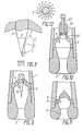
- the device according to the invention for cleaning the zone near the borehole contains a hollow body 1 (FIGS. 1 to 4) with an inlet channel 2. Inside the body 1, a swirl chamber 3 of an assembly for generating hydrodynamic waves with tangentially directed inlet channels 4 is arranged inside the body 1, a swirl chamber 3 of an assembly for generating hydrodynamic waves with tangentially directed inlet channels 4 is arranged.
- the swirl chamber 3 has a conically tapering (funnel-shaped) outlet channel 5 for the outlet of a working medium.
- the end face 6 of the chamber 3 is radially rounded, and a guide vane 8 is screwed onto it by means of screws 7 such that an annular channel 9 is formed between them, which communicates with the annular space of the bore.
- An annular mixing chamber 11 is formed in the borehole between the chamber 3 and a casing column 10, while an annular diffuser 12 is formed between the body 1 and the casing column 10.
- the channel 10, the mixing chamber 11 and the diffuser 12 form a jet pump, which generates a negative pressure in the working process and exerts a depression effect on a productive layer.
- the device is centered in the borehole by ribs 13.
- the device is connected to the casing column 14 by means of a conical thread.
- FIG. 5 shows an embodiment of the assembly for generating hydrodynamic waves with two additional swirl chambers 16, 17, which are arranged perpendicular to the axis of the body 1.
- the swirl chamber 17 is designed with two oppositely directed outlet channels 18.
- the tangentially directed inlet channels 19 and 20 of the chambers 16 and 17 are at an angle to their axes and are directed to opposite sides.
- the intersection of the tangential channels 19 and 20 can be circular or slit-shaped.
- a toroidal resonance chamber can be built into the wall of chamber 3 (FIGS. 6, 7) 21 with a combined annular inlet and outlet channel 22 (FIG. 6) and with a sharp edge 23.
- the swirl chamber 3 In order to keep cavitation wear of the swirl chamber 3 (FIGS. 8, 9) lower, it is provided with a conical waveguide 24.
- the swirl chamber 3 (FIG. 10) is provided with a resonance chamber 25, in which a piston 26 with a rod 27 is accommodated.
- the rod 27 is connected to the resonance chamber 25 by means of a screw connection.
- the cavity of the swirl chamber 3 (FIG. 11) is designed in a spherical shape.
- the device according to the invention for cleaning the zone near the borehole works as follows.
- the working medium liquid, gas or multi-phase liquid
- the pipes 14 (FIG. 1) into the inlet channel 2, from where it flows through the tangentially directed channels 4 into the swirl chamber 3.
- the liquid begins to circulate at a high rotation frequency (within the range of 10 3 to 1.5.10 3 s -1 ).
- 5 hydroacoustic waves are generated in the outlet channel.
- the turbulent pulsating flow from the outlet channel 5 is conveyed at a high speed in tangentially divergent directions, as indicated in FIGS. 1 and 12, and flows into the ring channel 9.
- the liquid is directed upwards from the annular channel 9 at a high speed and comes into an annular space - a mixing chamber 11 - and entrains the injected liquid from the zone near the borehole.
- the velocities of the flows to be mixed are balanced, and the kinetic energy of the working flow is partly converted into the potential energy of the mixed flow.
- the further conversion of the kinetic energy of the mixed flow into one Pressure energy occurs in the cavity of the diffuser 12.
- the effect of a jet pump is realized in the annular space, and an additional depression is created in the zone of a productive layer.
- the productive layer is exposed to both a depression and a wave effect. This creates mechanical activation processes in the zone near the borehole with signs of various nonlinear effects, the most important of which is the occurrence of hydrodynamic and hydroacoustic cavitation.
- the turbulently pulsating current is conveyed from the outlet channel 5 of the vortex chamber 3 in tangentially divergent directions and runs onto the sharp edge 23.
- the leading edge 23 hydroacoustic cutting-tone waves of low amplitude and self-excited bending vibrations of the edge 23 themselves (as with plate radiators) are excited. 6, the vibration of the leading edge 23 itself is indicated by dashed lines.
- the radial-tangential flow partly comes into the toroidal resonance chamber 21.
- the bending vibrations of the leading edge 23 cause a pressure pulsation in the toroidal resonance chamber 21.
- the ring channel 22 serves for the entry and exit of the liquid.
- the current emerging from the toroidal resonance chamber 21 interrupts the incoming current with the oscillation frequency of the leading edge 23, which is why hydroacoustic waves are additionally generated at the edge 23.
- the hydroacoustic waves and the cavitation effects in the zone near the borehole lead to the destruction of various deposits on the borehole wall and to the cleaning of the blocked pore channels in an oil layer.
- the action of depression activates the development of cavitation, accelerates it the inflow of stratified petroleum to the borehole contributes to the removal of cleaning products from the pore channels.
- the wave field has a significant effect on reducing the viscosity of the layer fluid and petroleum, while the simultaneous depression effect increases their inflow to the borehole.
- the device according to the invention can be used to clean the zone of a layer near the borehole in press-in bores in order to increase the absorption capacity of the layer. Without any design changes, it can be used as a shaft disperser, emulsifier, homogenizer of multi-phase liquids, for dispersing the drilling fluid and the cement slurry directly in the bore when carrying out the technological operations.
Description
Die vorliegende Einrichtung bezieht sich auf Einrichtungen zur Reinigung der bohrlochnahen Zone unter Benutzung von hydrodynamischen Wellen.The present device relates to devices for cleaning the zone near the borehole using hydrodynamic waves.
Es ist eine Einrichtung zur Reinigung der bohrlochnahen Zone (S.M. Godiev "Inspolzovanie vibratsii v. dobyche nefti" (Ausnutzung von Vibrationen in der Erdölförderung), 1977, Verlag "Nedra" (Moskau), S. 50, Fig. 27) bekannt, die einen hohlen Körper mit einer in diesem angeordneten Baugruppe zur Erzeugung von hydrodynamischen Wellen enthält, die eine Hülse darstellt, die im Körper mit Mindestabständen von seinen Wänden untergebracht ist. Die Hülse ist in Wälzlagern drehbar um ihre Achse angeordnet. An den Wänden des Körpers und der Hülse gibt es Öffnungen, die als Kanäle zum Durchgang der Flüssigkeit dienen. Der Körper weist radiale und die Hülse tangentiale Austrittskanäle auf. Um einen Leckverlust der Flüssigkeit durch den Ringspalt zu verhindern, wird im oberen Teil zwischen dem Körper und der Hülse eine Manschettendichtung angeordnet. Die Austrittskanäle der Hülse und des Körpers liegen in der gleichen Ebene.It is a device for cleaning the borehole zone (SM Godiev "Inspolzovanie vibratsii v. Dobyche nefti" (exploitation of vibrations in oil production), 1977, publisher "Nedra" (Moscow), p. 50, Fig. 27) known includes a hollow body with a hydrodynamic wave generating assembly disposed therein, which is a sleeve housed in the body at a minimum distance from its walls. The sleeve is rotatably arranged about its axis in rolling bearings. There are openings on the walls of the body and the sleeve which serve as channels for the passage of the liquid. The body has radial and the sleeve tangential outlet channels. In order to prevent leakage of the liquid through the annular gap, a sleeve seal is arranged in the upper part between the body and the sleeve. The outlet channels of the sleeve and the body lie in the same plane.
Die Einrichtung mit Steigrohren wird in ein Bohrloch bis auf die Höhe der Anordnung von Perforationsöffnungen abgesenkt. Durch die Steigrohre wird eine Arbeitsflüssigkeit eingepreßt. Die Flüssigkeit strömt, indem sie in den Hohlraum der Hülse kommt, auch in deren tangential angeordneten Austrittskanäle ein. Aus ihnen strömt die Flüssigkeit in die radialen Kanäle des Körpers und von da aus in den Ringraum des Bohrlochs ein.The device with risers is lowered into a borehole to the level of the arrangement of perforation openings. A working fluid is injected through the risers. The liquid flows by coming into the cavity of the sleeve, also in its tangentially arranged outlet channels. From them, the liquid flows into the radial channels of the body and from there into the annulus of the borehole.
Fließt die Flüssigkeit durch die tangentialen Kanäle der Hülse mit einer hohen Geschwindigkeit aus, wird an der Hülse ein Reaktions-Drehmoment erzeugt, wodurch sie in Drehung um den Körper versetzt wird. Hierbei werden die Kanäle der Hülse und des Körpers periodisch mit einer bestimmten Frequenz geschlossen und geöffnet. Durch die periodische Überdeckung der Kanäle in der bohrlochnahen Zone werden hydrodynamische Flüssigkeitsdruckimpulse erzeugt. Die Amplitude und die Frequenz der hydrodynamischen Impulse hängen vom Druck der gespülten Flüssigkeit und der Frequenz der Rotation der Hülse um den Körper ab.If the liquid flows out through the tangential channels of the sleeve at a high speed, a reaction torque is generated on the sleeve, causing it to rotate around the body. Here, the channels of the sleeve and the body are periodically closed and opened at a certain frequency. The periodic covering of the channels in the zone near the borehole generates hydrodynamic fluid pressure pulses. The amplitude and frequency hydrodynamic impulses depend on the pressure of the flushed fluid and the frequency of rotation of the sleeve around the body.
Die erzeugten hydrodynamischen Impulse tragen aber infolge deren unzureichender Stärke zur Zerstörung verschiedener Ablagerungen an den Bohrlochwänden nicht bei, ermöglichen keine Reinigung der verstopften Porenkanäle einer Erdölschicht.However, due to their insufficient strength, the generated hydrodynamic impulses do not contribute to the destruction of various deposits on the borehole walls, and do not enable the clogged pore channels of an oil layer to be cleaned.
Darüber hinaus weist die bekannte Einrichtung eine komplizierte Konstruktion auf, was deren Herstellungskosten erhöht und deren Betriebssicherheit herabsetzt, während das Vorhandensein der beweglichen Baugruppen und Teile in der Konstruktion deren intensiven mechanischen Verschleiß und eine Verringerung der Betriebsdauer der Einrichtung bewirkt.In addition, the known device has a complicated construction, which increases its manufacturing costs and reduces its operational safety, while the presence of the movable assemblies and parts in the construction causes their intensive mechanical wear and a reduction in the operating life of the device.
All das führt dazu, daß die bekannte Einrichtung keine wirksame Reinigung der bohrlochnahen Zone sichert und eine Steigerung der Ergiebigkeit einer Bohrung und der Erdölabgabe einer Schicht nicht fördert.All of this means that the known device does not ensure effective cleaning of the zone near the borehole and does not promote an increase in the productivity of a borehole and the oil release of a layer.
Eine Einrichtung zur Reinigung der bohrlochnahen Zone gemäß dem Oberbegriff des Patentanspruchs 1 ist bereits bekannt aus der GB-A-2 224 054. Dort wird vorgeschlagen, den durch die Wirbelkammer und deren Austrittskanal gebildeten Hohlraum pilzförmig auszugestalten, um im Bereich außerhalb des Austrittskanals einen sich im wesentliche ringförmig drehenden und mit dem Abstand vom Austrittskanal radial nach außen ausbreitenden Wirbel zu bilden, der im Zentrum einen Unterdruck aufweist und dort parallel zur Längsrichtung eine Gegenströmung erzeugt. Dieser sich vom Austrittskanal ausbreitende Wirbel hat die Aufgabe, außerhalb des Austrittskanals aus der Wirbelkammer angeordnete Schneidzähne, Brechrollen oder dergleichen zu reinigen.A device for cleaning the zone near the borehole according to the preamble of claim 1 is already known from GB-A-2 224 054. There it is proposed that the cavity formed by the swirl chamber and its outlet channel be made mushroom-shaped in order to be in the area outside the outlet channel to form an essentially annularly rotating vortex which spreads radially outwards with the distance from the outlet channel and which has a negative pressure in the center and generates a counterflow parallel to the longitudinal direction there. This vortex, which spreads from the outlet channel, has the task of cleaning cutting teeth, crushing rollers or the like which are arranged outside the outlet channel from the vortex chamber.
Der Erfindung liegt die Aufgabe zugrunde, eine derartige Einrichtung hinsichtlich ihrer Reinigungswirkung auf einfache Weise noch weiter zu verbessern.The invention has for its object to further improve such a device in terms of its cleaning effect in a simple manner.
Die Erfindung ist im Patentanspruch 1 gekennzeichnet und in Unteransprüchen derselben sind weitere Verbesserungen beansprucht.The invention is characterized in claim 1 and further improvements are claimed in the subclaims thereof.
Die Ausführung der Baugruppe zur Erzeugung von hydrodynamischen Wellen in Form einer Wirbelkammer mit den tangential angeordneten Eintrittskanälen gestattet es, hydroakustische Wellen mit einem breiten Frequenzspektrum zur Einwirkung auf eine produktive Schicht zu erzeugen. Darüber hinaus erlaubt es die Verwendung der Wirbelkammer, eine Unterdruckzone, d.h. eine Depression, in der bohrlochnahen Zone zu schaffen. All das verbessert die Reinigung der Porenkanäle beträchtlich und vergrößert den Erdölzufluß zur Bohrung.The design of the assembly for generating hydrodynamic waves in the form of a swirl chamber with the tangentially arranged inlet channels makes it possible to generate hydroacoustic waves with a wide frequency spectrum for acting on a productive layer. In addition, the use of the swirl chamber allows a vacuum zone, i.e. to create a depression in the borehole zone. All of this significantly improves the cleaning of the pore channels and increases the oil flow to the well.
Die Einengung des Austrittskanals der Wirbelkammer ist dadurch bedingt, daß mit abnehmendem Kanaldurchmesser die Rotationsfrequenz der Flüssigkeit proportional zum Verhältnis der Durchmesser der Wirbelkammer und des Austrittsstutzens zunimmt, und dementsprechend nimmt auch die Frequenz der Wellenstrahlung zu.The narrowing of the outlet channel of the swirl chamber is due to the fact that as the channel diameter decreases, the frequency of rotation of the liquid increases in proportion to the ratio of the diameter of the swirl chamber and the outlet nozzle, and accordingly the frequency of the wave radiation also increases.
Erfindungsgemäß ist die Baugruppe zur Erzeugung von hydrodynamischen Wellen mit mindestens einer zusätzlichen Wirbelkammer versehen, die in Strömungsrichtung vor der Wirbelkammer angeordnet und mit dem Hohlraum des Hohlkörpers ebenfalls durch tangential angeordnete Eintrittskanäle verbunden ist sowie zwei sich kegelig verjüngende, entgegengesetzt gerichtete Austrittskanäle aufweist, die im wesentlichen rechtwinklig zur Längsrichtung des Hohlkörpers verlaufen.According to the invention, the assembly for generating hydrodynamic waves is provided with at least one additional swirl chamber, which is arranged in the direction of flow in front of the swirl chamber and is also connected to the cavity of the hollow body by tangentially arranged inlet channels and has two conically tapering, oppositely directed outlet channels, which essentially have run at right angles to the longitudinal direction of the hollow body.
Dies gestattet es, die Zone der Einwirkung auf eine Erdölschicht zu vergrößern und den Prozeß der Reinigung der bohrlochnahen Zone zu intensivieren.This allows the zone of exposure to a petroleum layer to be enlarged and the process of cleaning the zone near the borehole to be intensified.
Es ist zweckmäßig, daß in der Wand der Wirbelkammer auf dem Abschnitt der Anordnung ihres Austrittskanals ein mit dem Innenraum der Wirbelkammer verbundener toroidaler Hohlraum ausgeführt ist.It is expedient that a toroidal cavity connected to the interior of the vortex chamber is made in the wall of the vortex chamber on the section of the arrangement of its outlet channel.
Der in der Wand der Wirbelkammer ausgeführte toroidale Resonanzraum dient zur Amplitudenverstärkung der erzeugten Wellen unter den Resonanzbedinungen. Außerdem tragen zur Amplitudenverstärkung Wellen bei, die durch eine scharfe Kante des Eintrittskanals des toroidalen Hohlraumes erzeugt werden. Wenn der radial-tangentianale Strom mit einer hohen Geschwindigkeit auf die scharfe Kante am Eingang der Resonanzkammer aufläuft, werden daran Selbstschwingungen geringer Amplitude erregt, die Schneidenton-Wellen erzeugen, deren Frequenz von der Ausströmungsgeschwindigkeit, der Dichte der injizierten Flüssigkeit und der Steifheit der Resonatorwand selbst abhängig ist.The toroidal resonance chamber in the wall of the vortex chamber serves to amplify the generated waves under the resonance conditions. Waves that are generated by a sharp edge of the inlet channel of the toroidal cavity also contribute to the amplification of the amplitude. When the radial-tangentian current hits the sharp edge at the entrance of the resonance chamber at a high speed, self-oscillations of low amplitude are excited, which produce cutting-edge sound waves whose frequency depends on the outflow speed and the density of the injected Liquid and the stiffness of the resonator wall itself is dependent.
Es ist vorteilhaft, daß die Baugruppe zur Erzeugung von hydrodynamischen Wellen mit einer Leitschaufel versehen ist, die im Unterteil der Wirbelkammer in der Weise angeordnet ist, daß zwischen der äußeren Stirnfläche der Wirbelkammer und der ihr zugekehrten Innenfläche der Leitschaufel, die abgerundet ausgeführt sind, ein Ringkanal gebildet wird.It is advantageous that the assembly for generating hydrodynamic waves is provided with a guide vane, which is arranged in the lower part of the vortex chamber in such a way that a rounded between the outer end face of the vortex chamber and the inner surface of the vane facing it Ring channel is formed.
Die in der Nähe der Stirnfläche der Wand der Wirbelkammer angeordnete Leitschaufel bildet einen Ringkanal - Düse - und formiert aus dem aus dem Austrittskanal ausfließenden radialtangentialen Strom einen Ringstrom und richtet ihn durch den Ringraum nach oben. Dies trägt zur Verbesserung der Güte des Vakuums und der Depressionseinwirkung auf die bohrlochnahe Zone bei.The guide vane arranged near the end face of the wall of the vortex chamber forms an annular channel - nozzle - and forms an annular flow from the radial-tangential flow flowing out of the outlet channel and directs it upward through the annular space. This helps to improve the quality of the vacuum and the effect of depression on the zone near the borehole.
Die Ausführung der Stirnfläche der Wand der Wirbelkammer mit einer radialen Abrundung gestattet es, die hydrodynamischen Verluste bei einer Umlenkung und Formierung des nach oben gerichteten Stroms geringer zu halten.The design of the end face of the wall of the swirl chamber with a radial rounding makes it possible to keep the hydrodynamic losses lower when the upward flow is deflected and formed.
Um einen Unterdruckkern in der Wirbelkammer zu erzeugen und die Schwingungsamplitude des Flüssigkeitsdrucks zu erhöhen, ist es notwendig, daß die tangential angeordneten Eintrittskanäle der zusätzlichen Wirbelkammer unter einem Winkel zu deren Achse ausgeführt und nach entgegengesetzten Seiten gerichtet sind.In order to generate a vacuum core in the swirl chamber and to increase the oscillation amplitude of the liquid pressure, it is necessary that the tangentially arranged inlet channels of the additional swirl chamber are designed at an angle to their axis and are directed to opposite sides.
Zweckmäßig ist, daß der Hohlraum der Wirbelkammer kugelförmig ausgebildet ist.It is expedient that the cavity of the swirl chamber is spherical.
Die Wahl der Form der Wirbelkammer in Kugelgestalt ist auf eine hohe Amplitude der durch im Selbstschwingungszustand mit einer periodischen hydraulischen Selbstsperrung des Austrittskanals arbeitende Kugelstrahler erzeugten Wellen zurückzuführen.The choice of the shape of the swirl chamber in spherical shape is due to a high amplitude of the waves generated by spherical emitters working in the self-oscillation state with a periodic hydraulic self-locking of the outlet channel.
Es ist bevorzugt, daß die Wirbelkammer mit einem in dieser Richtung ihrer Längsachse verlaufenden und in ihrem Oberteil befestigten kegelförmigen Hohlleiter versehen ist, wobei die Kegelverjüngung seiner Seitenfläche aus der Beziehung![]()
ermittelt wird, worin
- ϕ
- die Kegelverjüngung der Seitenfläche des Hohlleiters;
- 0'
- der kritische Gleitwinkel einer in der Wirbelkammer erzeugten, auf den Hohlleiter einfallenden Welle
is determined wherein
- ϕ
- the taper of the side surface of the waveguide;
- 0 '
- the critical sliding angle of a wave generated in the swirl chamber and incident on the waveguide
Die Ausstattung der Wirbelkammer mit dem kegelförmigen Hohlleiter bezweckt die Verhinderung eines hydrodynamischen und hydroakustischen Kavitationsverschleißes des Zentralteiles des Kopfes der Wirbelkammer. Darüber hinaus bringt der kegelförmige Hohlleiter die Kavitationsblasen außerhalb der Wirbelkammer.The purpose of equipping the vortex chamber with the conical waveguide is to prevent hydrodynamic and hydroacoustic cavitation wear on the central part of the head of the vortex chamber. In addition, the conical waveguide brings the cavitation bubbles outside the vortex chamber.
Die Auswahl der Kegelverjüngung ϕ des Hohlleiters nicht oberhalb eines Doppelwertes des kritischen Gleitwinkels 0'einer Einfallswelle (d.h. θ < ϕ ≤ 20') ist darin begründet, daß die Grenzfläche der zwei Medien (injizierte Flüssigkeit und Metall) mit verschiedenen Dichten und Kompressibilitäten eine Reflexions-, Absorptions- und brechende Fläche darstellt. Liegt der Gleitwinkel 0 der Einfallswelle nicht oberhalb des kritischen Gleitwinkels 0', findet eine Totalreflexion der Einfallswelle statt, derartige Welle überträgt keine Energie vom ersten Medium (von der Flüssigkeit) zum zweiten Medium (zum Metall), und die Gesamtenergie der Einfallwelle wird von der Oberfläche des Hohlleiters zum ersten Medium rückgestrahlt. Als Gleitwinkel 0 wird ein Winkel zwischen der Ausbreitungswinkel der Welle und der Grenzfläche bezeichnet. Der Kosinus des kritischen Gleitwinkels 0' ist gleich dem Brechungskoeffizienten des zweiten Mediums in Bezug auf das erste Medium (Snelliussches Gesetz), d.h.![]()
- c
- die Schallgeschwindigkeit in der injizierten Flüssigkeit;
- c1
- die Schallgeschwindigkeit im Metall;
- n
- der Brechungskoeffizient
- c
- the speed of sound in the injected liquid;
- c 1
- the speed of sound in the metal;
- n
- the refractive index
Die Kegelverjüngung ϕ des Hohlleiters darf nicht oberhalb von 20' liegen, d.h. 0 < ϕ ≤ 20'.The taper taper ϕ of the waveguide must not be above 20 ', i.e. 0 <ϕ ≤ 20 '.
Es ist auch sinnvoll, daß die Baugruppe zur Erzeugung von hydrodynamischen Wellen mit einer Resonanzkammer versehen ist, deren Hohlraum mit dem Hohlraum der Wirbelkammer verbunden und in der mit der Möglichkeit einer Verschiebung in Längsrichtung ein Kolben mit einer Stange untergebracht ist.It also makes sense that the assembly for generating hydrodynamic waves is provided with a resonance chamber, the cavity of which is connected to the cavity of the swirl chamber and in which a piston with a rod is accommodated with the possibility of displacement in the longitudinal direction.
Dies gestattet es, die Frequenz der erzeugten Wellen auf eine Resonanzfrequenz bei verschiedenen Durchflußmengen und Dichten der injizierten Flüssigkeit abzustimmen. Die Abstimmung auf die Resonanzfrequenz erfolgt durch Verschiebung des Kolbens mittels einer Schneckenstange und durch Änderung des Volumens der Resonanzkammer unter dem Kolben.This allows the frequency of the waves generated to be tuned to a resonance frequency at different flow rates and densities of the injected liquid. The tuning to the resonance frequency takes place by moving the piston by means of a worm rod and by changing the volume of the resonance chamber under the piston.
Die Einrichtung zur Reinigung der bohrlochnahen Zone, die mit der erfindungsgemäßen Wirbelkammer versehen ist, gestattet es also, eine komplexe Bohrlochbehandlung in Verbindung mit thermisch-physikalisch-chemischen Verfahren durchzuführen sowie die Produktivität und die Erdölabgabe einer Schicht zu steigern. Die Einrichtung weist eine einfache Konstruktion auf, ist betriebssicher und herstellungsgerecht.The device for cleaning the zone near the borehole, which is provided with the swirl chamber according to the invention, makes it possible to carry out a complex borehole treatment in connection with thermal-physical-chemical processes and to increase the productivity and the oil release of a layer. The device has a simple construction, is reliable and suitable for production.
Die vorliegende Erfindung wird nachstehend an konkreten Ausführungsbeispielen anhand der beigelegten Zeichnungen näher erläutert. Es zeigen:
- Fig. 1 die Gesamtansicht einer Einrichtung zur Reinigung der bohrlochnahen Zone;
- Fig. 2 einen II-II-Schnitt nach Fig. 1;
- Fig. 3 eine Ansicht in Pfeilrichtung A zu Fig. 1;
- Fig. 4 eine Ansicht in Pfeilrichtung B. zu Fig. 2;
- Fig. 5 die Gesamtansicht der erfindungsgemäßen Einrichtung zur Reinigung der bohrlochnahen Zone mit zwei zusätzlichen Wirbelkammern;
- Fig. 6 die Gesamtansicht einer Einrichtung zur Reinigung der bohrlochnahen Zone mit einem toroidalen Hohlraum in der Wand der Wirbelkammer;
- Fig. 7 einen VII-VII-Schnitt zu Fig. 6;
- Fig. 8 eine Wirbelkammer mit einem kegelförmigen Hohlleiter;
- Fig. 9 einen kegelförmigen Hohlleiter;
- Fig. 10 eine Wirbelkammer mit einer Resonanzkammer;
- Fig. 11 eine Wirbelkammer mit einem kugelförmigen Innenraum;
- Fig. 12 eine Skizze für den Ausfluß einer Arbeitsflüssigkeit aus dem Austrittskanal der Wirbelkammer.
- 1 shows the overall view of a device for cleaning the zone near the borehole;
- FIG. 2 shows a II-II section according to FIG. 1;
- Fig. 3 is a view in the direction of arrow A to Fig. 1;
- Fig. 4 is a view in the direction of arrow B. to Fig. 2;
- 5 shows the overall view of the device according to the invention for cleaning the zone near the borehole with two additional swirl chambers;
- 6 shows the overall view of a device for cleaning the zone near the borehole with a toroidal cavity in the wall of the vortex chamber;
- Fig. 7 is a VII-VII section to Fig. 6;
- 8 shows a swirl chamber with a conical waveguide;
- 9 shows a conical waveguide;
- 10 shows a swirl chamber with a resonance chamber;
- 11 shows a swirl chamber with a spherical interior;
- Fig. 12 is a sketch for the outflow of a working fluid from the outlet channel of the swirl chamber.
Die erfindungsgemäße Einrichtung zur Reinigung der bohrlochnahen Zone enthält einen Hohlkörper 1 (Fig. 1 bis 4) mit einem Eintrittskanal 2. Innerhalb des Körpers 1 ist eine Wirbelkammer 3 einer Baugruppe zur Erzeugung von hydrodynamischen Wellen mit tangential gerichteten Eintrittskanälen 4 angeordnet. Die Wirbelkammer 3 weist einen sich kegelig verjüngenden (trichterförmigen) Austrittskanal 5 zum Austritt eines Arbeitsmediums auf. Die Stirnfläche 6 der Kammer 3 ist radial abgerundet, und an sie ist mittels Schrauben 7 eine Leitschaufel 8 derart angeschraubt, daß zwischen ihnen ein Ringkanal 9 gebildet ist, der mit dem Ringraum der Bohrung kommuniziert. Im Bohrloch ist zwischen der Kammer 3 und einer Futterrohrkolonne 10 eine ringformige Mischkammer 11 gebildet, während zwischen dem Körper 1 und der Futterrohrkolonne 10 eine ringförmiger Diffusor 12 gebildet ist. Auf solche Weise bilden der Kanal 10, die Mischkammer 11 und der Diffusor 12 eine Strahlpumpe, die im Arbeitsvorgang einen Unterdruck erzeugt und eine Depressionswirkung auf eine produktive Schicht ausübt. Die Einrichtung wird im Bohrloch durch Rippen 13 zentriert. Die Einrichtung wird mit der Futterrohrkolonne 14 mittels Kegelgewinde verbunden.The device according to the invention for cleaning the zone near the borehole contains a hollow body 1 (FIGS. 1 to 4) with an
Um die Wellenwirkung auf eine Schicht zu erhöhen, besitzt die Baugruppe zur Erzeugung von hydrodynamischen Wellen mindestens eine zusätzliche Wirbelkanmer. In Fig. 5 ist eine Ausführungsform der Baugruppe zur Erzeugung von hydrodynamischen Wellen mit zwei zusätzlichen Wirbelkammern 16, 17, die senkrecht zur Achse des Körpers 1 angeordnet sind, dargestellt. Die Wirbelkammer 17 ist mit zwei entgegengesetzt gerichteten Austrittskanälen 18 ausgeführt. Die tangential gerichteten Eintrittskanäle 19 und 20 der Kammern 16 bzw. 17 liegen unter einem Winkel zu deren Achsen und sind nach entgegengesetzten Seiten gerichtet. Der Schnitt der tangentialen Kanäle 19 und 20 kann kreis- oder schlitzförmig ausgebildet werden.In order to increase the wave effect on a layer, the assembly for generating hydrodynamic waves has at least one additional swirl joint. FIG. 5 shows an embodiment of the assembly for generating hydrodynamic waves with two
Um die Amplitude der erzeugten Wellen zu vergrößern, kann in der Wand der Kammer 3 (Fig. 6, 7) eine toroidale Resonanzkammer 21 mit einem vereinigten ringförmigen Ein- und Austrittskanal 22 (Fig. 6) und mit einer scharfen Kante 23 ausgeführt werden.In order to increase the amplitude of the waves generated, a toroidal resonance chamber can be built into the wall of chamber 3 (FIGS. 6, 7) 21 with a combined annular inlet and outlet channel 22 (FIG. 6) and with a
Um einen Kavitationsverschleiß der Wirbelkammer 3 (Fig. 8, 9) geringer zu halten, ist sie mit einem kegelförmigen Hohlleiter 24 versehen.In order to keep cavitation wear of the swirl chamber 3 (FIGS. 8, 9) lower, it is provided with a
Zur Erhöhung der Effektivität der Wellenwirkung auf eine Schicht ist die Wirbelkammer 3 (Fig. 10) mit einer Resoanzkammer 25 versehen, in der ein Kolben 26 mit einer Stange 27 untergebracht ist. Die Stange 27 ist mit der Resonanzkammer 25 mittels einer Schraubenverbindung verbunden. Durch Einund Ausschrauben der Stange 27 wird das Volumen der Resonanzkammer 25 und folglich auch die Amplitudenfrequenzkennlinie der Einrichtung geändert.To increase the effectiveness of the wave effect on a layer, the swirl chamber 3 (FIG. 10) is provided with a
Um die Amplitude der erzeugten Wellen und die Effektivität der Wellenwirkung auf eine Schicht zu erhöhen, ist der Hohlraum der Wirbelkammer 3 (Fig. 11) in Kugelform ausgebildet.In order to increase the amplitude of the waves generated and the effectiveness of the wave effect on a layer, the cavity of the swirl chamber 3 (FIG. 11) is designed in a spherical shape.
Die erfindungsgemäße Einrichtung zur Reinigung der bohrlochnahen Zone arbeitet wie folgt. Das Arbeitsmedium (Flüssigkeit, Gas oder Mehrphasenflüssigkeit) wird durch die Rohre 14 (Fig. 1) in den Eintrittskanal 2 gefördert, von wo aus sie durch die tangential gerichteten Kanäle 4 in die Wirbelkammer 3 einströmt. In der Wirbelkammer 3 beginnt die Flüssigkeit mit einer hohen Rotationsfrequenz (in Grenzen von 103 bis 1,5.103 s-1) umzulaufen. Hierbei werden im Austrittskanal 5 hydroakustische Wellen erzeugt. Ferner wird der turbulent pulsierende Strom aus dem Austrittskanal 5 mit einer hohen Geschwindigkeit in tangential divergierenden Richtungen, wie dies in Fig. 1. und 12 angedeutet ist, gefördert und strömt in den Ringkanal 9 ein. Die Flüssigkeit wird aus dem Ringkanal 9 mit einer hohen Geschwindigkeit nach oben gerichtet und kommt in einen Ringraum - eine Mischkammer 11 - und reißt die injizierte Flüssigkeit aus der bohrlochnahen Zone mit. In der Kammer 11 werden die Geschwindigkeiten der durchzumischenden Ströme ausgeglichen, und die kinetische Energie des Arbeitsstroms wird zum Teil in die Potentialenergie der durchgemischten Strömung umgesetzt. Die weitere Umwandlung der kinetischen Energie der durchgemischten Strömung in eine Druckenergie erfolgt im Hohlraum des Diffusors 12. Auf solche Weise wird im Ringraum der Effekt einer Strahlpumpe realisiert, und in der Zone einer produktiven Schicht wird eine zusätzliche Depression geschaffen. Hierbei wird die produktive Schicht zugleich einer Depressions- und einer Wellenwirkung ausgesetzt. Hierbei entstehen in der bohrlochnahen Zone mechanische Aktivierungsvorgänge mit Anzeichen verschiedener nichtlinearer Effekte, von denen das Auftreten einer hydrodynamischen und hydroakustischen Kavitation der wichtigste ist.The device according to the invention for cleaning the zone near the borehole works as follows. The working medium (liquid, gas or multi-phase liquid) is conveyed through the pipes 14 (FIG. 1) into the
Beim Vorhandensein der toroidalen Resonanzkammer 21 (Fig. 6) wird der turbulent pulsierende Strom aus dem Austrittskanal 5 der Wirbelkammer 3 in tangential divergierenden Richtungen gefördert und läuft auf die scharfe Kante 23 auf. An der Eintrittskante 23 werden hydroakustische Schneidenton-Wellen geringer Amplitude und selbsterregter Biegungsschwingungen der Kante 23 selbst (wie bei Plattenstrahlern) erregt. In Fig. 6 ist die Schwingung der Eintrittskante 23 selbst gestrichelt angedeutet. Der radial-tangentiale Strom kommt teilweise in die toroidale Resonanzkammer 21. Die Biegungsschwingungen der Eintrittskante 23 bewirken eine Druckpulsation in der toroidalen Resonanzkammer 21. Der Ringkanal 22 dient zum Ein- und Austritt der Flüssigkeit. Im Zusammenhang damit unterbricht der aus der toroidalen Resonanzkammer 21 austretende Strom den eintretenden Strom mit der Schwingungsfrequenz der Eintrittskante 23, weshalb an der Kante 23 zusätzlich hydroakustische Wellen erzeugt werden.In the presence of the toroidal resonance chamber 21 (FIG. 6), the turbulently pulsating current is conveyed from the
Zur Erregung intensiver hydroakustischer Wellen ist es notwendig, daß die Eigenfrequenzen sämtlicher Quellen der Wellenerzeugung und sämtlicher im Generator befindlichen Resonatoren betragsmäßig einander gleich oder nahe sind, d.h.![]()
![]()
Die hydroakustischen Wellen und die Kavitationseffekte in der bohrlochnahen Zone führen zu einer Zerstörung verschiedener Ablagerungen an der Bohrlochwand und zur Reinigung der verstopften Porenkanäle einer Erdölschicht. Die Depressionseinwirkung aktiviert die Entstehung der Kavitation, beschleunigt den Zufluß eines Schichterdöls zum Bohrloch, trägt zur Entfernung von Reinigungsprodukten aus den Porenkanälen bei. Darüber hinaus wirkt sich das Wellenfeld auf eine Verringerung der Viskosität von Schichtfluid und Erdöl beträchtlich aus, während die gleichzeitige Depressionswirkung deren Zufluß zum Bohrloch vergrößert.The hydroacoustic waves and the cavitation effects in the zone near the borehole lead to the destruction of various deposits on the borehole wall and to the cleaning of the blocked pore channels in an oil layer. The action of depression activates the development of cavitation, accelerates it the inflow of stratified petroleum to the borehole contributes to the removal of cleaning products from the pore channels. In addition, the wave field has a significant effect on reducing the viscosity of the layer fluid and petroleum, while the simultaneous depression effect increases their inflow to the borehole.
Die erfindungsgemäße Einrichtung kann zur Reinigung der bohrlochnahen Zone einer Schicht bei Einpreßbohrungen verwendet werden, um die Aufnahmefähigkeit der Schicht zu erhöhen. Ohne konstruktive Änderungen kann sie als Wellendispergator, -emulgator, -homogenisator von Mehrphasenflüssigkeiten, für ein Dispergieren der Bohrspülung und der Zementschlämme unmittelbar in der Bohrung bei der Durchführung der technologischen Arbeitsgänge eingesetzt werden.The device according to the invention can be used to clean the zone of a layer near the borehole in press-in bores in order to increase the absorption capacity of the layer. Without any design changes, it can be used as a shaft disperser, emulsifier, homogenizer of multi-phase liquids, for dispersing the drilling fluid and the cement slurry directly in the bore when carrying out the technological operations.
Claims (9)
- A device for cleaning a well-bore-surrounding zone comprising a hollow body (1) with an assembly being disposed therein for generating hydrodynamic waves, wherein a whirl chamber (3) extending in the longitudinal direction of hollow body (1) is connected with the cavity of the hollow body (1) via tangentially disposed entrance channels (4) and comprises a conically tapering exit channel (5) in the longitudinal direction and wherein the entrance channels (4) are situated in the region of the side opposite the exit channel (5)
characterized in
that the assembly comprises at least one additional whirl chamber (16, 17) which is disposed in the flow direction before the whirl chamber (3) and connected with the cavity of the hollow body (1) via tangentially disposed entrance channels (19, 20) and comprises two conically tapering, oppositely directed exit channels (18) extending substantially perpendicularly to the longitudinal direction of the hollow body (1). - A device according to claim 1,
characterized in
that the substantially tangentially disposed entrance channels (19, 20) of the additional whirl chamber (16, 17) are realized under an angle with respect to the axis thereof and directed to opposite sides. - A device according to claim 1 or 2,
characterized in
that two additional whirl chambers (16, 17) are disposed within the hollow body (1) before the whirl chamber (3) disposed at the end thereof. - A device according to any of claims 1-3,
characterized in
that the cavity of the whirl chamber (3) is formed to be spherical. - A device according to any of the preceding claims,
characterized in
that a toroidal resonance chamber (21) is disposed in the wall of the whirl chamber (3) on the section where the exit channel (5) thereof is disposed, the entrance channel (22) of said resonance chamber (21) being disposed in the region of the exit channel (5) from the whirl chamber (3) and at the same time constituting the exit channel thereof. - A device according to claim 5,
characterized in
that the entrance channel (22) from the resonance chamber (21) comprises a sharp entrance edge (23). - A device accorrding to any of the preceding claims,
characterized in
that a rounded guide blade (8) is disposed in the lower part of the whirl chamber (3) in such a manner that an annular channel (9) is formed between the outer front face of the whirl chamber (3) and the inner surface of the guide blade (8) facing it. - A device according to any of the preceding claims,
characterized in
that the whirl chamber (3) comprises, in the region of the side opposite to the exit channel (5), a hollow-conical reflector (24) substantially extending in the longitudinal direction whose conical tapering for its side faces results from the relation
- A device according to any of the preceding claims,
characterized in
that the cavity of the whirl chamber (3) is connected with a resonance chamber (25) wherein a piston (26) being adjustable in the longitudinal direction and comprising a rod (27) is situated.
Applications Claiming Priority (2)
| Application Number | Priority Date | Filing Date | Title |
|---|---|---|---|
| SU4928469 | 1991-05-06 | ||
| SU4928469 | 1991-05-06 |
Publications (2)
| Publication Number | Publication Date |
|---|---|
| EP0512331A1 EP0512331A1 (en) | 1992-11-11 |
| EP0512331B1 true EP0512331B1 (en) | 1996-09-18 |
Family
ID=21570312
Family Applications (1)
| Application Number | Title | Priority Date | Filing Date |
|---|---|---|---|
| EP92106953A Expired - Lifetime EP0512331B1 (en) | 1991-05-06 | 1992-04-23 | Device for cleaning the well-bore-surrounding-zone |
Country Status (4)
| Country | Link |
|---|---|
| US (1) | US5311955A (en) |
| EP (1) | EP0512331B1 (en) |
| JP (1) | JPH06257371A (en) |
| DE (1) | DE59207154D1 (en) |
Cited By (1)
| Publication number | Priority date | Publication date | Assignee | Title |
|---|---|---|---|---|
| RU2553687C1 (en) * | 2014-04-15 | 2015-06-20 | Открытое акционерное общество "Татнефть" имени В.Д. Шашина | Device for pulse injection of liquid to reservoir |
Families Citing this family (13)
| Publication number | Priority date | Publication date | Assignee | Title |
|---|---|---|---|---|
| GB9704213D0 (en) * | 1997-02-28 | 1997-04-16 | Ocre Scotland Ltd | Drilling apparatus |
| US6470980B1 (en) * | 1997-07-22 | 2002-10-29 | Rex A. Dodd | Self-excited drill bit sub |
| US6477217B1 (en) * | 1999-02-19 | 2002-11-05 | Agency Of Industrial Science And Technology Japan Atomic Energy Research Institute | Target for neutron scattering installation |
| WO2005078231A1 (en) * | 2004-02-04 | 2005-08-25 | David Scott Chrisman | Tool and method for drilling, reaming and cutting |
| GB0606335D0 (en) * | 2006-03-30 | 2006-05-10 | Specialised Petroleum Serv Ltd | Wellbore cleaning |
| KR101145189B1 (en) * | 2009-07-16 | 2012-05-14 | (주)동우기계 | Apparatus for excavation |
| RU2448242C1 (en) * | 2010-12-07 | 2012-04-20 | Анатолий Георгиевич Малюга | Intensification method of hydrocarbon flow from productive formations of wells and cavitating device for its implementation |
| RU2454527C1 (en) * | 2010-12-27 | 2012-06-27 | Общество с ограниченной ответственностью "ЛУКОЙЛ-Инжиниринг" (ООО "ЛУКОЙЛ-Инжиниринг") | Device for acoustical effect on productive formation |
| US20160040504A1 (en) * | 2014-08-08 | 2016-02-11 | Baker Hughes Incorporated | Suction Nozzle |
| RU171177U1 (en) * | 2017-02-08 | 2017-05-23 | Рустам Рафаэльевич Саиткулов | DEVICE FOR VIBROWAVE INFLUENCE ON PRODUCTIVE LAYERS OF AQUARIUM AND OIL AND GAS WELLS |
| GB201714789D0 (en) | 2017-09-14 | 2017-11-01 | Innovative Drilling Systems Ltd | Downhole cleaning tool |
| EP3767069A1 (en) * | 2019-07-15 | 2021-01-20 | Vortex Oil Engineering S.A. | A vortex device and a method for hydroacoustic treatment of a fluid |
| RU2713846C1 (en) * | 2019-10-11 | 2020-02-07 | Антолий Георгиевич Малюга | Cavitation device for stimulation of oil recovery of formations |
Family Cites Families (8)
| Publication number | Priority date | Publication date | Assignee | Title |
|---|---|---|---|---|
| US4391339A (en) * | 1978-08-04 | 1983-07-05 | Hydronautics, Incorporated | Cavitating liquid jet assisted drill bit and method for deep-hole drilling |
| US4389071A (en) * | 1980-12-12 | 1983-06-21 | Hydronautics, Inc. | Enhancing liquid jet erosion |
| US4474251A (en) * | 1980-12-12 | 1984-10-02 | Hydronautics, Incorporated | Enhancing liquid jet erosion |
| US4744420A (en) * | 1987-07-22 | 1988-05-17 | Atlantic Richfield Company | Wellbore cleanout apparatus and method |
| GB2224054B (en) * | 1988-09-29 | 1992-06-03 | Shell Int Research | Drill bit equipped with vortex nozzles and vortex nozzle for use in the bit |
| FR2659384B1 (en) * | 1990-03-07 | 1995-09-15 | Ungemach Pierre | DEVICE FOR CURING AND CLEANING WELLS AFFECTED BY DEPOSITS AND INCRUSTATIONS. |
| US5199512A (en) * | 1990-09-04 | 1993-04-06 | Ccore Technology And Licensing, Ltd. | Method of an apparatus for jet cutting |
| US5086974A (en) * | 1990-12-18 | 1992-02-11 | Nlb Corp. | Cavitating jet nozzle |
-
1992
- 1992-04-23 DE DE59207154T patent/DE59207154D1/en not_active Expired - Fee Related
- 1992-04-23 EP EP92106953A patent/EP0512331B1/en not_active Expired - Lifetime
- 1992-05-05 US US07/878,476 patent/US5311955A/en not_active Expired - Fee Related
- 1992-05-06 JP JP4113816A patent/JPH06257371A/en not_active Withdrawn
Cited By (1)
| Publication number | Priority date | Publication date | Assignee | Title |
|---|---|---|---|---|
| RU2553687C1 (en) * | 2014-04-15 | 2015-06-20 | Открытое акционерное общество "Татнефть" имени В.Д. Шашина | Device for pulse injection of liquid to reservoir |
Also Published As
| Publication number | Publication date |
|---|---|
| US5311955A (en) | 1994-05-17 |
| JPH06257371A (en) | 1994-09-13 |
| DE59207154D1 (en) | 1996-10-24 |
| EP0512331A1 (en) | 1992-11-11 |
Similar Documents
| Publication | Publication Date | Title |
|---|---|---|
| EP0512331B1 (en) | Device for cleaning the well-bore-surrounding-zone | |
| DE1533607C3 (en) | Earth drilling method and apparatus for carrying out this method | |
| DE69930751T2 (en) | drilling turbine | |
| EP0346417A1 (en) | Whirl nozzle for atomizing a liquid | |
| DE62111T1 (en) | METHOD AND DEVICE FOR INCREASING THE EROSION EFFECT OF A LIQUID JET. | |
| DE60221277T2 (en) | LIQUID DRILL HEAD | |
| DE2839387C2 (en) | Process for generating hydrodynamic vibrations in a liquid and device for carrying out the process | |
| WO1996009112A1 (en) | Device for generating liquid systems, in particular emulsions, suspensions or the like, in a hydrodynamic cavitation field | |
| EP0580099A2 (en) | Ultrasonic gas meter | |
| WO2018121815A1 (en) | Drilling device | |
| EP1638675A1 (en) | Dispersing device | |
| DE3228038A1 (en) | Liquid/gas separator | |
| EP0512330B1 (en) | Drill bit | |
| EP0512329B1 (en) | Core bit with hydrodynamic core destruction | |
| DE1551223A1 (en) | Gap sealing between a rotating and a stationary part of flow machines, in particular of water turbines and centrifugal pumps | |
| RU2247227C2 (en) | Jet end piece for hydraulic sand jet perforator | |
| EP3659977B1 (en) | Device for the treatment of liquids by means of hydromechanical cavitation and vacuum | |
| EP0267285A1 (en) | Gas-liquid separator | |
| DE3700587A1 (en) | Process for atomising and atomiser of a high-pressure liquid jet emerging from a nozzle | |
| EP3659979A1 (en) | Device for the treatment of liquids by means of hydro-mechanical cavitation and vacuum | |
| DE2658619A1 (en) | Regulating valve generating vortex - is downstream side of valve passage to reduce noise of flow-through valve | |
| DE102019115626B3 (en) | Vortex nozzle module, fluid swirl device, and sanitary fitting | |
| DE2301194C3 (en) | Device for drilling earth formations | |
| RU2049218C1 (en) | Device for cleaning and vibration treatment of well walls | |
| EP0420981A1 (en) | Device for generating acoustic oscillations in a liquid medium |
Legal Events
| Date | Code | Title | Description |
|---|---|---|---|
| PUAI | Public reference made under article 153(3) epc to a published international application that has entered the european phase |
Free format text: ORIGINAL CODE: 0009012 |
|
| AK | Designated contracting states |
Kind code of ref document: A1 Designated state(s): BE DE FR GB IT |
|
| 17P | Request for examination filed |
Effective date: 19930318 |
|
| 17Q | First examination report despatched |
Effective date: 19930730 |
|
| GRAG | Despatch of communication of intention to grant |
Free format text: ORIGINAL CODE: EPIDOS AGRA |
|
| GRAH | Despatch of communication of intention to grant a patent |
Free format text: ORIGINAL CODE: EPIDOS IGRA |
|
| GRAH | Despatch of communication of intention to grant a patent |
Free format text: ORIGINAL CODE: EPIDOS IGRA |
|
| ITF | It: translation for a ep patent filed |
Owner name: STUDIO FERRARIO |
|
| GRAA | (expected) grant |
Free format text: ORIGINAL CODE: 0009210 |
|
| AK | Designated contracting states |
Kind code of ref document: B1 Designated state(s): BE DE FR GB IT |
|
| RIN1 | Information on inventor provided before grant (corrected) |
Inventor name: MUCHUTDINOW, RASCHID GABDULATIFOWITSCH Inventor name: SACHAROW, JURIJ PETROWITSCH Inventor name: WASILIEW, REMUS CHUSAINOWITSCH Inventor name: MUFASALOW, ROBERT SCHAKUROWITSCH Inventor name: GANIJEW, RIFNER WASSILOWITSCH |
|
| ET | Fr: translation filed | ||
| GBT | Gb: translation of ep patent filed (gb section 77(6)(a)/1977) |
Effective date: 19960919 |
|
| REF | Corresponds to: |
Ref document number: 59207154 Country of ref document: DE Date of ref document: 19961024 |
|
| PLBE | No opposition filed within time limit |
Free format text: ORIGINAL CODE: 0009261 |
|
| STAA | Information on the status of an ep patent application or granted ep patent |
Free format text: STATUS: NO OPPOSITION FILED WITHIN TIME LIMIT |
|
| 26N | No opposition filed | ||
| PGFP | Annual fee paid to national office [announced via postgrant information from national office to epo] |
Ref country code: BE Payment date: 19990422 Year of fee payment: 8 |
|
| PG25 | Lapsed in a contracting state [announced via postgrant information from national office to epo] |
Ref country code: BE Free format text: LAPSE BECAUSE OF NON-PAYMENT OF DUE FEES Effective date: 20000430 |
|
| PGFP | Annual fee paid to national office [announced via postgrant information from national office to epo] |
Ref country code: GB Payment date: 20001005 Year of fee payment: 9 |
|
| PGFP | Annual fee paid to national office [announced via postgrant information from national office to epo] |
Ref country code: FR Payment date: 20001017 Year of fee payment: 9 |
|
| BERE | Be: lapsed |
Owner name: WAVE TEC G.M.B.H. Effective date: 20000430 |
|
| PGFP | Annual fee paid to national office [announced via postgrant information from national office to epo] |
Ref country code: DE Payment date: 20010322 Year of fee payment: 10 |
|
| PG25 | Lapsed in a contracting state [announced via postgrant information from national office to epo] |
Ref country code: GB Free format text: LAPSE BECAUSE OF NON-PAYMENT OF DUE FEES Effective date: 20010423 |
|
| PG25 | Lapsed in a contracting state [announced via postgrant information from national office to epo] |
Ref country code: FR Free format text: THE PATENT HAS BEEN ANNULLED BY A DECISION OF A NATIONAL AUTHORITY Effective date: 20010430 |
|
| GBPC | Gb: european patent ceased through non-payment of renewal fee |
Effective date: 20010423 |
|
| REG | Reference to a national code |
Ref country code: FR Ref legal event code: ST |
|
| PG25 | Lapsed in a contracting state [announced via postgrant information from national office to epo] |
Ref country code: DE Free format text: LAPSE BECAUSE OF NON-PAYMENT OF DUE FEES Effective date: 20021101 |
|
| PG25 | Lapsed in a contracting state [announced via postgrant information from national office to epo] |
Ref country code: IT Free format text: LAPSE BECAUSE OF NON-PAYMENT OF DUE FEES Effective date: 20050423 |