EP0511299B1 - Process for manufacturing a hose coupling component intended particularly for a hose connection between a turbo unit and an air cooler, and a hose coupling component of this type - Google Patents
Process for manufacturing a hose coupling component intended particularly for a hose connection between a turbo unit and an air cooler, and a hose coupling component of this type Download PDFInfo
- Publication number
- EP0511299B1 EP0511299B1 EP91903725A EP91903725A EP0511299B1 EP 0511299 B1 EP0511299 B1 EP 0511299B1 EP 91903725 A EP91903725 A EP 91903725A EP 91903725 A EP91903725 A EP 91903725A EP 0511299 B1 EP0511299 B1 EP 0511299B1
- Authority
- EP
- European Patent Office
- Prior art keywords
- flange
- hose
- coupling component
- sleeve
- pipe sleeve
- Prior art date
- Legal status (The legal status is an assumption and is not a legal conclusion. Google has not performed a legal analysis and makes no representation as to the accuracy of the status listed.)
- Expired - Lifetime
Links
Images

Classifications
-
- F—MECHANICAL ENGINEERING; LIGHTING; HEATING; WEAPONS; BLASTING
- F16—ENGINEERING ELEMENTS AND UNITS; GENERAL MEASURES FOR PRODUCING AND MAINTAINING EFFECTIVE FUNCTIONING OF MACHINES OR INSTALLATIONS; THERMAL INSULATION IN GENERAL
- F16L—PIPES; JOINTS OR FITTINGS FOR PIPES; SUPPORTS FOR PIPES, CABLES OR PROTECTIVE TUBING; MEANS FOR THERMAL INSULATION IN GENERAL
- F16L33/00—Arrangements for connecting hoses to rigid members; Rigid hose connectors, i.e. single members engaging both hoses
- F16L33/20—Undivided rings, sleeves or like members contracted on the hose or expanded in the hose by means of tools; Arrangements using such members
- F16L33/207—Undivided rings, sleeves or like members contracted on the hose or expanded in the hose by means of tools; Arrangements using such members only a sleeve being contracted on the hose
- F16L33/2071—Undivided rings, sleeves or like members contracted on the hose or expanded in the hose by means of tools; Arrangements using such members only a sleeve being contracted on the hose the sleeve being a separate connecting member
-
- Y—GENERAL TAGGING OF NEW TECHNOLOGICAL DEVELOPMENTS; GENERAL TAGGING OF CROSS-SECTIONAL TECHNOLOGIES SPANNING OVER SEVERAL SECTIONS OF THE IPC; TECHNICAL SUBJECTS COVERED BY FORMER USPC CROSS-REFERENCE ART COLLECTIONS [XRACs] AND DIGESTS
- Y10—TECHNICAL SUBJECTS COVERED BY FORMER USPC
- Y10T—TECHNICAL SUBJECTS COVERED BY FORMER US CLASSIFICATION
- Y10T29/00—Metal working
- Y10T29/49—Method of mechanical manufacture
- Y10T29/49826—Assembling or joining
- Y10T29/49908—Joining by deforming
- Y10T29/49909—Securing cup or tube between axially extending concentric annuli
- Y10T29/49913—Securing cup or tube between axially extending concentric annuli by constricting outer annulus
Definitions
- the present invention relates to a process for manufacturing a hose coupling component, which comprises a pipe sleeve, which is provided at a first end with a peripheral flange projecting from the lateral surface of the sleeve, said flange having a side facing towards a second end of the pipe sleeve and inclined towards said first end, said flange forming an outer limitation of a circumferential groove which is open towards said first end for a gasket ring, said pipe sleeve having as well between its ends a portion with a circumferential profile.
- the invention also relates to a hose coupling component of this type.
- Such a coupling component is used, for example, in hose connections between a turbo charger unit and an air cooler in turbo charged internal combustion engines.
- the hose connections are intended to absorb the relative movement between the spring suspended engine and the charge-air cooler rigidly mounted on the vehicle frame and it must therefore be able to withstand high temperatures, excessive pressure and mechanical stresses.
- a known hose coupling of the type in question consists of an inner pipe sleeve, over which a flexible hose is forced, and an outer ring which is pressed over the hose coaxially with the inner sleeve.
- the inner sleeve is made of aluminum and the details described in the introduction, such as the flange, the peripheral gasket groove and the profiles are made by turning a sleeve blank. In addition to these details, a radial flange is made during the lathe turning of the sleeve blank axially inside the first mentioned flange.
- the radial flange is intended, inter alia, to serve as an end abutment for the hose and thereby assure that the hose will always be forced the same distance onto the sleeve for assembly, which is important to prevent variations in the total length of the hose and the hose connection between vehicles produced on the assembly line.
- the known coupling component due to its two flanges and the peripheral gasket groove at one end, thus has a relatively complicated shape which cannot be produced effectively in any other manner than by machining.
- the purpose of the present invention is to achieve, through a simple modification of the design of the known coupling component, a simpler and less expensive method for its manufacture.
- a bowl is pressed from a sheet metal element, that the upper edge portion of the bowl is folded, so that said flange and the circumferential groove are formed, that the bottom of the bowl is cut away, and that a portion between the flange and an opposite end of the sheet metal element is press rolled so that a profile in the form of an annular depression is formed in the lateral surface of the pipe sleeve.
- Figure 1 shows a known design, where 1 designates a corrugated hose of elastic material, which is forced onto an inner coupling sleeve 2 of turned aluminum. An outer ring 3 of steel is pressed over the hose.
- the sleeve 2 has a profiled portion in the form of a ridge 4, while the ring 3 has a complementary depression 5 for securely fixing the hose on the inner sleeve.
- the sleeve 2 has at its left hand end a first flange 6 which forms an end abutment for the hose 1, and a second flange 7 which forms the outer boundary of a groove 8 for a gasket ring.
- the flange 7 is intended to be brought into contact with a similar but mirror image flange on the component (not shown) to which the hose is to be connected.
- the flange 7 has an inclined side 9 and thus forms together with said mirror image flange a two-part V-shaped bead, which is held together with the aid of a V-shaped clamp (not shown).
- FIG. 2 shows a hose coupling component according to the invention.
- the hose 1 is in this case forced onto an inner coupling sleeve 12 of pressed sheet metal.
- An outer ring 13 of steel is pressed over the hose 1, which has an inner peripheral bead 14, which lies in a peripheral depression 15 in the sleeve.
- the bead 14 and the depression 15 thus are means which determine how far over the sleeve 12 the hose 1 is to be forced. They also contribute to creating a tight and secure connection between the hose and the sleeve.
- the left hand end of the sleeve 12 is folded in a press so that a flange 16 is formed, corresponding to the flange 7 of the known sleeve.
- This flange 16 also has a groove 18 for a gasket ring and has an inclined side 19.
- the flange 16 can be brought into abutment with a similar mirror image flange of pressed sheet metal or turned aluminum on the component to which the hose is to be connected and can be fixed thereto in a known manner with the help of a V-shaped clamp.
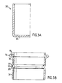
- the sleeve 12 When manufacturing the sleeve 12 according to the invention, one starts with a sheet metal blank, which is deep drawn so as to form a bowl or cup 30 with the shape formed in Figure 3a. After deep drawing, the bottom 34 of the bowl (see Figure 3a) is cut off, and the annular depression 15 for the bead 14 is created by press rolling.
- the invention thus provides a coupling sleeve which can be manufactured at substantially lower cost than the known coupling sleeve described without any negative defect on function or reliability.
Abstract
Description
- The present invention relates to a process for manufacturing a hose coupling component, which comprises a pipe sleeve, which is provided at a first end with a peripheral flange projecting from the lateral surface of the sleeve, said flange having a side facing towards a second end of the pipe sleeve and inclined towards said first end, said flange forming an outer limitation of a circumferential groove which is open towards said first end for a gasket ring, said pipe sleeve having as well between its ends a portion with a circumferential profile. The invention also relates to a hose coupling component of this type.
- Such a coupling component is used, for example, in hose connections between a turbo charger unit and an air cooler in turbo charged internal combustion engines. The hose connections are intended to absorb the relative movement between the spring suspended engine and the charge-air cooler rigidly mounted on the vehicle frame and it must therefore be able to withstand high temperatures, excessive pressure and mechanical stresses.
- A known hose coupling of the type in question consists of an inner pipe sleeve, over which a flexible hose is forced, and an outer ring which is pressed over the hose coaxially with the inner sleeve. The inner sleeve is made of aluminum and the details described in the introduction, such as the flange, the peripheral gasket groove and the profiles are made by turning a sleeve blank. In addition to these details, a radial flange is made during the lathe turning of the sleeve blank axially inside the first mentioned flange. The radial flange is intended, inter alia, to serve as an end abutment for the hose and thereby assure that the hose will always be forced the same distance onto the sleeve for assembly, which is important to prevent variations in the total length of the hose and the hose connection between vehicles produced on the assembly line.
- The known coupling component, due to its two flanges and the peripheral gasket groove at one end, thus has a relatively complicated shape which cannot be produced effectively in any other manner than by machining.
- The purpose of the present invention is to achieve, through a simple modification of the design of the known coupling component, a simpler and less expensive method for its manufacture.
- This is achieved according to the invention by virtue of the fact that a bowl is pressed from a sheet metal element, that the upper edge portion of the bowl is folded, so that said flange and the circumferential groove are formed, that the bottom of the bowl is cut away, and that a portion between the flange and an opposite end of the sheet metal element is press rolled so that a profile in the form of an annular depression is formed in the lateral surface of the pipe sleeve.
- This simplification of the end portion of the pipe sleeve due to elimination of the flange serving as a hose abutment, makes it possible to manufacture the pipe sleeve of the coupling component by a pressing process instead of by machining. The annular depression formed between the two steps serves as a reference for axially positioning the hose on the sleeve. The hose can thus be made with an inner peripheral bead at a specific distance from the end of the hose, and when the hose is forced onto the sleeve, the bead will slip into the annular depression and indicate the correct relative positioning of the components.
- The invention will be described in more detail below with reference to examples shown in the accompanying drawings, where
- Figure 1 shows a partially sectioned side view of a previously known coupling component with hose,
- Figure 2 is a view corresponding to Figure 1 of a coupling component according to the invention, and
- Figures 3a and 3b are cross-sections through the inner pipe sleeve in Figure 2 in different stages of manufacture.
- Figure 1 shows a known design, where 1 designates a corrugated hose of elastic material, which is forced onto an inner coupling sleeve 2 of turned aluminum. An
outer ring 3 of steel is pressed over the hose. The sleeve 2 has a profiled portion in the form of a ridge 4, while thering 3 has acomplementary depression 5 for securely fixing the hose on the inner sleeve. - The sleeve 2 has at its left hand end a first flange 6 which forms an end abutment for the hose 1, and a
second flange 7 which forms the outer boundary of agroove 8 for a gasket ring. Theflange 7 is intended to be brought into contact with a similar but mirror image flange on the component (not shown) to which the hose is to be connected. Theflange 7 has aninclined side 9 and thus forms together with said mirror image flange a two-part V-shaped bead, which is held together with the aid of a V-shaped clamp (not shown). - Figure 2 shows a hose coupling component according to the invention. The hose 1 is in this case forced onto an
inner coupling sleeve 12 of pressed sheet metal. An outer ring 13 of steel is pressed over the hose 1, which has an innerperipheral bead 14, which lies in aperipheral depression 15 in the sleeve. Thebead 14 and thedepression 15 thus are means which determine how far over thesleeve 12 the hose 1 is to be forced. They also contribute to creating a tight and secure connection between the hose and the sleeve. - The left hand end of the
sleeve 12 is folded in a press so that aflange 16 is formed, corresponding to theflange 7 of the known sleeve. Thisflange 16 also has agroove 18 for a gasket ring and has aninclined side 19. Theflange 16 can be brought into abutment with a similar mirror image flange of pressed sheet metal or turned aluminum on the component to which the hose is to be connected and can be fixed thereto in a known manner with the help of a V-shaped clamp. - When manufacturing the
sleeve 12 according to the invention, one starts with a sheet metal blank, which is deep drawn so as to form a bowl orcup 30 with the shape formed in Figure 3a. After deep drawing, thebottom 34 of the bowl (see Figure 3a) is cut off, and theannular depression 15 for thebead 14 is created by press rolling. - The invention thus provides a coupling sleeve which can be manufactured at substantially lower cost than the known coupling sleeve described without any negative defect on function or reliability.
Claims (2)
- Method of manufacturing a hose coupling component, comprising a pipe sleeve, which is provided at a first end with a periferal flange projecting from the lateral surface of the sleeve, said flange having a side facing towards a second end of the pipe sleeve and inclined towards said first end, said flange forming an outer limitation of a circumferential groove which is open towards said first end for a gasket ring, said pipe sleeve having as well between its ends a portion with a circumferential profile, characterized in that a bowl (30) is pressed from a sheet metal element, that the upper edge portion of the bowl is folded, so that said flange (16) and the circumferential groove (18) are formed, that the bottom (34) of the bowl is cut away, and that a portion between the flange and an opposite end of the sheet metal element is press rolled so that a profile in the form of an annular depression (15) is formed in the lateral surface of the pipe sleeve
- Hose coupling component, comprising a pipe sleeve, which is provided at a first end with a circumferential flange extending from the lateral surface of the sleeve, and having a side facing a second end and inclined towards the first end, said flange forming the outer limitation of a circumferential groove open towards the first end, for a gasket ring, said pipe sleeve having between its ends a portion with a periferal profile, characterized in that the pipe sleeve (12) consists of a pressed sheet metal element made by the method of claim 1, which has at a first end a folded edge portion, forming said flange (16) and said circumferential groove (18), said pipe sleeve having a profile portion in the form of an annular depression (15) in the lateral surface of the pipe sleeve between the flange and its opposite end.
Applications Claiming Priority (2)
| Application Number | Priority Date | Filing Date | Title |
|---|---|---|---|
| SE9000150A SE465479B (en) | 1990-01-16 | 1990-01-16 | PROCEDURES FOR PREPARING A HOSE CONNECTING PART, EXAMPLE FOR HOSE CONNECTIONS BETWEEN TURBO COVER AND CHARGING COOLERS, AND A CONNECTING PART OF THIS TYPE |
| SE9000150 | 1990-01-16 |
Publications (2)
| Publication Number | Publication Date |
|---|---|
| EP0511299A1 EP0511299A1 (en) | 1992-11-04 |
| EP0511299B1 true EP0511299B1 (en) | 1993-09-08 |
Family
ID=20378259
Family Applications (1)
| Application Number | Title | Priority Date | Filing Date |
|---|---|---|---|
| EP91903725A Expired - Lifetime EP0511299B1 (en) | 1990-01-16 | 1991-01-16 | Process for manufacturing a hose coupling component intended particularly for a hose connection between a turbo unit and an air cooler, and a hose coupling component of this type |
Country Status (5)
| Country | Link |
|---|---|
| US (1) | US5310224A (en) |
| EP (1) | EP0511299B1 (en) |
| DE (1) | DE69100354T2 (en) |
| SE (1) | SE465479B (en) |
| WO (1) | WO1991010859A1 (en) |
Families Citing this family (10)
| Publication number | Priority date | Publication date | Assignee | Title |
|---|---|---|---|---|
| JPH0735271A (en) * | 1993-07-20 | 1995-02-07 | Usui Internatl Ind Co Ltd | Metallic small-diameter piping connecting/fixing method |
| US6604400B1 (en) * | 1998-01-15 | 2003-08-12 | Arlington Industries, Inc. | Electrical connector |
| US6234543B1 (en) | 1998-12-16 | 2001-05-22 | Dan T. Logan | Device and method for coupling a rigid pipe to a flexible hose |
| SE526730C2 (en) | 2003-12-17 | 2005-11-01 | Volvo Lastvagnar Ab | Connection for connecting a hose to a rigid pipe connection |
| US8677966B2 (en) * | 2011-01-20 | 2014-03-25 | Advanced Flow Engineering, Inc. | Air intake flow device and system |
| US20120190290A1 (en) * | 2011-01-20 | 2012-07-26 | Shahriar Nick Niakan | Air intake flow device and system |
| CN106662276B (en) * | 2014-04-30 | 2020-12-18 | Abc科技股份有限公司 | Air duct with in-mold molded pressure resistant ring |
| ITMI20140945A1 (en) * | 2014-05-22 | 2015-11-22 | Bremboflex S P A | METHOD FOR MAKING A HOSE FITTING FOR A FLEXIBLE HOSE |
| CN107110005B (en) * | 2014-11-03 | 2019-06-28 | 康明斯有限公司 | The method that pressurizing air tracheae and management thermal expansion are supported using wear-resisting external member |
| US10030796B2 (en) | 2015-06-30 | 2018-07-24 | Cnh Industrial America Llc | Vacuum hose coupling with quick lock feature |
Family Cites Families (16)
| Publication number | Priority date | Publication date | Assignee | Title |
|---|---|---|---|---|
| US787144A (en) * | 1904-06-18 | 1905-04-11 | James Bropson | Pipe-union. |
| US1936552A (en) * | 1932-10-08 | 1933-11-21 | Scovill Manufacturing Co | Hose coupling |
| US2319024A (en) * | 1941-06-26 | 1943-05-11 | Herman H Wehringer | Hose coupling |
| GB579395A (en) * | 1944-03-08 | 1946-08-01 | Fritz Gustav Leonard Brissman | Improvements in hose couplings |
| US2438530A (en) * | 1945-01-25 | 1948-03-30 | George V Woodling | Coupling member |
| US2432598A (en) * | 1945-03-16 | 1947-12-16 | Weatherhead Co | Hose end |
| GB704494A (en) * | 1952-01-23 | 1954-02-24 | Aeroquip Corp | Improvements in and relating to the construction and manufacture of detachable re-usable hose fittings |
| FR1167276A (en) * | 1957-02-27 | 1958-11-24 | Bendix Aviat Corp | Connection end |
| US3207537A (en) * | 1964-03-16 | 1965-09-21 | K & E Ind Inc | Pipe connections |
| US3501171A (en) * | 1967-07-10 | 1970-03-17 | Alfred Morton Baron | Connector assembly for fluid conduits |
| GB1251811A (en) * | 1968-01-12 | 1971-11-03 | ||
| US3549180A (en) * | 1968-05-16 | 1970-12-22 | Scovill Manufacturing Co | Hose and hose coupling assembly |
| CH555022A (en) * | 1972-08-10 | 1974-10-15 | Oetiker Hans | PIPE CONNECTION. |
| JPS5319130B2 (en) * | 1972-09-08 | 1978-06-19 | ||
| US4660867A (en) * | 1986-04-22 | 1987-04-28 | The Gates Rubber Company | Coupled hose assembly |
| US5127157A (en) * | 1989-02-06 | 1992-07-07 | Hans Oetiker | Method of fastening hose to nipple |
-
1990
- 1990-01-16 SE SE9000150A patent/SE465479B/en not_active IP Right Cessation
-
1991
- 1991-01-16 US US07/867,188 patent/US5310224A/en not_active Expired - Lifetime
- 1991-01-16 DE DE91903725T patent/DE69100354T2/en not_active Expired - Fee Related
- 1991-01-16 WO PCT/SE1991/000026 patent/WO1991010859A1/en active IP Right Grant
- 1991-01-16 EP EP91903725A patent/EP0511299B1/en not_active Expired - Lifetime
Also Published As
| Publication number | Publication date |
|---|---|
| US5310224A (en) | 1994-05-10 |
| SE9000150L (en) | 1991-07-17 |
| DE69100354T2 (en) | 1994-01-05 |
| EP0511299A1 (en) | 1992-11-04 |
| WO1991010859A1 (en) | 1991-07-25 |
| SE9000150D0 (en) | 1990-01-16 |
| SE465479B (en) | 1991-09-16 |
| DE69100354D1 (en) | 1993-10-14 |
Similar Documents
| Publication | Publication Date | Title |
|---|---|---|
| EP0511299B1 (en) | Process for manufacturing a hose coupling component intended particularly for a hose connection between a turbo unit and an air cooler, and a hose coupling component of this type | |
| US5253773A (en) | Filler tube for liquid containers | |
| US5836366A (en) | Method of fitting an assembly formed of a tire and of a tread strip support | |
| EP0612926B1 (en) | Ball joint equipped with a dust cover | |
| US6398269B1 (en) | Tube connection between a collector of a motor vehicle heat exchanger and an exterior line | |
| US4684157A (en) | Hose coupling | |
| JPS6310935Y2 (en) | ||
| US4531483A (en) | Lip sealing ring in an internal combustion engine | |
| US4921368A (en) | Fastening of a sealing bellows to the joint housing of a ball joint | |
| US4098137A (en) | Pulley and method of making same | |
| US6230679B1 (en) | Valve stem seal with pads and tangs | |
| GB2031074A (en) | High-temperature seal | |
| JPH07237044A (en) | Manufacture of automobile wheel | |
| EP0797036A1 (en) | Coupling for two metal pipes | |
| JPH0239672B2 (en) | ||
| JPS6043155A (en) | Mounting method of engine oil pan | |
| JPH0339639Y2 (en) | ||
| EP1111213A1 (en) | Gasket for spigot joints in exhaust tubes of internal comustion engines | |
| JP4018248B2 (en) | Automotive disc wheel | |
| JPS6347515A (en) | Fixing method for dust cover of ball joint | |
| GB2094908A (en) | An edge seal ring | |
| JPH023003Y2 (en) | ||
| JPH08121666A (en) | Hose with joint part | |
| JP4045000B2 (en) | Synthetic resin filler pipe | |
| JPH06108953A (en) | Manufacture of internal combustion engine starter head and starter head manufactured by said method |
Legal Events
| Date | Code | Title | Description |
|---|---|---|---|
| PUAI | Public reference made under article 153(3) epc to a published international application that has entered the european phase |
Free format text: ORIGINAL CODE: 0009012 |
|
| 17P | Request for examination filed |
Effective date: 19920717 |
|
| AK | Designated contracting states |
Kind code of ref document: A1 Designated state(s): DE FR GB |
|
| 17Q | First examination report despatched |
Effective date: 19930120 |
|
| GRAA | (expected) grant |
Free format text: ORIGINAL CODE: 0009210 |
|
| AK | Designated contracting states |
Kind code of ref document: B1 Designated state(s): DE FR GB |
|
| REF | Corresponds to: |
Ref document number: 69100354 Country of ref document: DE Date of ref document: 19931014 |
|
| ET | Fr: translation filed | ||
| PLBE | No opposition filed within time limit |
Free format text: ORIGINAL CODE: 0009261 |
|
| STAA | Information on the status of an ep patent application or granted ep patent |
Free format text: STATUS: NO OPPOSITION FILED WITHIN TIME LIMIT |
|
| 26N | No opposition filed | ||
| REG | Reference to a national code |
Ref country code: GB Ref legal event code: IF02 |
|
| PGFP | Annual fee paid to national office [announced via postgrant information from national office to epo] |
Ref country code: DE Payment date: 20090108 Year of fee payment: 19 |
|
| PGFP | Annual fee paid to national office [announced via postgrant information from national office to epo] |
Ref country code: GB Payment date: 20090114 Year of fee payment: 19 |
|
| PGFP | Annual fee paid to national office [announced via postgrant information from national office to epo] |
Ref country code: FR Payment date: 20090113 Year of fee payment: 19 |
|
| GBPC | Gb: european patent ceased through non-payment of renewal fee |
Effective date: 20100116 |
|
| REG | Reference to a national code |
Ref country code: FR Ref legal event code: ST Effective date: 20100930 |
|
| PG25 | Lapsed in a contracting state [announced via postgrant information from national office to epo] |
Ref country code: FR Free format text: LAPSE BECAUSE OF NON-PAYMENT OF DUE FEES Effective date: 20100201 |
|
| PG25 | Lapsed in a contracting state [announced via postgrant information from national office to epo] |
Ref country code: DE Free format text: LAPSE BECAUSE OF NON-PAYMENT OF DUE FEES Effective date: 20100803 |
|
| PG25 | Lapsed in a contracting state [announced via postgrant information from national office to epo] |
Ref country code: GB Free format text: LAPSE BECAUSE OF NON-PAYMENT OF DUE FEES Effective date: 20100116 |