EP0510688A1 - Discharge excitation pulsed laser oscillation device - Google Patents
Discharge excitation pulsed laser oscillation device Download PDFInfo
- Publication number
- EP0510688A1 EP0510688A1 EP92107055A EP92107055A EP0510688A1 EP 0510688 A1 EP0510688 A1 EP 0510688A1 EP 92107055 A EP92107055 A EP 92107055A EP 92107055 A EP92107055 A EP 92107055A EP 0510688 A1 EP0510688 A1 EP 0510688A1
- Authority
- EP
- European Patent Office
- Prior art keywords
- main
- discharge
- laser
- preionizer
- recess
- Prior art date
- Legal status (The legal status is an assumption and is not a legal conclusion. Google has not performed a legal analysis and makes no representation as to the accuracy of the status listed.)
- Granted
Links
Images

Classifications
-
- H—ELECTRICITY
- H01—ELECTRIC ELEMENTS
- H01S—DEVICES USING THE PROCESS OF LIGHT AMPLIFICATION BY STIMULATED EMISSION OF RADIATION [LASER] TO AMPLIFY OR GENERATE LIGHT; DEVICES USING STIMULATED EMISSION OF ELECTROMAGNETIC RADIATION IN WAVE RANGES OTHER THAN OPTICAL
- H01S3/00—Lasers, i.e. devices using stimulated emission of electromagnetic radiation in the infrared, visible or ultraviolet wave range
- H01S3/02—Constructional details
- H01S3/03—Constructional details of gas laser discharge tubes
- H01S3/038—Electrodes, e.g. special shape, configuration or composition
- H01S3/0385—Shape
-
- H—ELECTRICITY
- H01—ELECTRIC ELEMENTS
- H01S—DEVICES USING THE PROCESS OF LIGHT AMPLIFICATION BY STIMULATED EMISSION OF RADIATION [LASER] TO AMPLIFY OR GENERATE LIGHT; DEVICES USING STIMULATED EMISSION OF ELECTROMAGNETIC RADIATION IN WAVE RANGES OTHER THAN OPTICAL
- H01S3/00—Lasers, i.e. devices using stimulated emission of electromagnetic radiation in the infrared, visible or ultraviolet wave range
- H01S3/09—Processes or apparatus for excitation, e.g. pumping
- H01S3/097—Processes or apparatus for excitation, e.g. pumping by gas discharge of a gas laser
- H01S3/0977—Processes or apparatus for excitation, e.g. pumping by gas discharge of a gas laser having auxiliary ionisation means
-
- H—ELECTRICITY
- H01—ELECTRIC ELEMENTS
- H01S—DEVICES USING THE PROCESS OF LIGHT AMPLIFICATION BY STIMULATED EMISSION OF RADIATION [LASER] TO AMPLIFY OR GENERATE LIGHT; DEVICES USING STIMULATED EMISSION OF ELECTROMAGNETIC RADIATION IN WAVE RANGES OTHER THAN OPTICAL
- H01S3/00—Lasers, i.e. devices using stimulated emission of electromagnetic radiation in the infrared, visible or ultraviolet wave range
- H01S3/02—Constructional details
- H01S3/03—Constructional details of gas laser discharge tubes
- H01S3/038—Electrodes, e.g. special shape, configuration or composition
- H01S3/0384—Auxiliary electrodes, e.g. for pre-ionisation or triggering, or particular adaptations therefor
Definitions
- This invention relates to discharge excitation pulsed laser oscillation devices (pulsed transversely excited gas laser devices), and more particularly to the electrode structure of the discharge excitation pulsed laser oscillation devices.
- Fig. 2 is a schematic sectional view of a conventional discharge excitation pulsed laser oscillation device (pulsed transversely excited gas laser device), showing a section thereof perpendicular to the optical axis of the laser.
- the device is disclosed in: Marchetti and E. Penco, "A new type of corona-discharge photoionization source for gas lasers", Journal of Applied Physics 56(11), December 1984, pp. 3163 - 3168.
- a pair of main electrodes 1 and 2 opposing each other extend parallel to the optical axis of the laser.
- Across the main electrodes 1 and 2 is formed a main discharge 3.
- a laser gas flow 4 is supplied from a laser gas supply device (not shown), along a directional perpendicular to the optical axis of the laser, to the region between the main electrodes 1 and 2.
- a pair of preionizers 5 disposed on the upstream and the downstream side (with respect to the direction of the laser gas flow 4) of the main electrodes 1 and 2 preionize the laser gas between the main electrodes 1 and 2 such that the main discharge 3 is generated.
- Each preionizer 5 consists of: a hollow dielectric pipe 6, an auxiliary electrode 7 inserted into the bore of the dielectric pipe 6 and a conductor wire 8 which is attached over the outer surface of the dielectric pipe 6 and is kept at the same potential as the main electrode 2.
- the laser gas is supplied from a laser gas supply device to the region between the main electrodes 1 and 2.
- the corona discharge 9 starts from the point at which the conductor wire 8 and the dielectric pipe 6 are in contact and covers the outer surface of the dielectric pipe 6.
- the ultraviolet radiation radiated from the corona discharge 9 preionizes the laser gas between the main electrodes 1 and 2.
- the preionized laser gas begins to discharge, and the main discharge 3 is generated across the main electrode 1 and main electrode 2.
- the laser gas is excited by the main discharge 3, such that the laser commences to oscillate in a direction perpendicular to the surface of the drawing in Fig. 2.
- the discharge remnants such as the ions and metastable gas molecules and atoms generated by the main discharge 3, and particles sputtered out from the electrodes, are carried downstream with the laser gas flow 4.
- the new laser gas is supplied to the region between the main electrodes 1 and 2 and the ultraviolet radiation is radiated thereto from both sides.
- the number of preionized electrons (photoelectrons) remains constant and the distribution thereof is symmetric for the upstream and the downstream side (with respect to the laser gas flow 4) in the region between the main electrodes 1 and 2.
- the main discharge 3 is maintained constant throughout the operation.
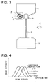
- Fig. 3 is a schematic sectional view of a conventional discharge excitation excimer laser oscillation device.
- the device is disclosed in: T. S. Fahlen, "HIGH-AVERAGE-POWER EXCIMER LASER", DOE/SF/90024--T2,1977, United States Energy Research and Development Administration.
- a tube 1a having an outer diameter of 1/4 inches is mounted on an end of a main electrode 1 opposing the other main electrode 2.
- the preionizer 5, including a hollow dielectric pipe 6 and an auxiliary electrode 7 which consists of a wire inserted into the bore of the dielectric pipe 6, is disposed at the downstream side (with respect to the laser gas flow 4) of the main electrode 1 such that the dielectric pipe 6 is partly in contact with the main electrode 1.
- the operation of the laser device of Fig 3 is similar to that of the laser device of Fig. 2.
- a voltage is applied across the main electrode 1 and the auxiliary electrode 7, such that the corona discharge 9 is generated from the point where the main electrode 1 and the dielectric pipe 6 are in contact, and thence covers the whole dielectric pipe 6.
- the laser gas between the main electrodes 1 and 2 are preionized by the ultraviolet radiation radiated from the corona discharge 9.
- the preionized laser gas commences to discharge, thereby generating the main discharge 3.
- the laser gas is excited by the main discharge 3, such that the laser oscillates in the direction perpendicular to the surface of the drawing.
- the preionizer 5 is disposed only at the downstream side of the main electrode 1.
- the above conventional laser devices have the following disadvantages.
- the preionizers 5 are disposed on both the upstream and downstream side (with respect to the laser gas flow 4) of the main electrodes 1 and 2.
- the ultraviolet radiation radiated from the preionizer 5 at the downstream side is absorbed by the discharge remnants generated by the main discharge 3.
- the center of the distribution of preionized electrons (photoelectrons) is shifted to the upstream side.
- the central position of the laser beam is also shifted to the upstream side (with respect to the laser gas flow 4) as the oscillation frequency increases.
- the preionizer 5 is disposed only at the downstream side (with respect to the laser gas flow 4) of the main electrodes 1 and 2.
- the ultraviolet radiation radiated from the preionizer 5 is absorbed by the discharge remnants generated by the main discharge 3,
- the oscillation frequency increases, the number of preionized electrons decreases, and the homogeneity of the main discharge 3 is deteriorated.
- the energy is not effectively deposited into the laser gas.
- the laser oscillation efficiency deteriorates and the output power decreases.
- a discharge excitation pulsed laser oscillation device which comprises a pair of main electrodes having main surfaces opposing each other across a main discharge gap and extending perpendicular to an optical axis of laser, wherein one of the main electrodes has a recess formed on the main surface thereof to an upstream side of a location where a foot of a main discharge across the main electrodes is formed; laser gas supply means for supply a laser gas to a main discharge gap region between the pair of main electrodes; and a preionizer means substantially accommodated within the recess formed on the one of the main electrodes.
- the preionizer means is a corona discharge preionizer which comprises: a dielectric pipe substantially accommodated within the recess, and an auxiliary electrode inserted in the dielectric pipe.
- a side wall of the recess has a projection extending sideways therefrom to contact with an outer surface portion of the preionizer, the preionizer being separated from the recess except at the outer surface portion in contact with the projection.
- Fig. 1 is a schematic sectional view of a discharge excitation pulsed laser oscillation device according to an embodiment of this invention.
- the parts 1 through 9 correspond to those described above with reference to Figs. 2 and 3.
- a main electrode 1 opposes an other main electrode 2 to form a main discharge 3 therebetween.
- the laser gas flow 4 is supplied from a laser gas supply device (not shown) disposed to the right of the main electrodes 1 and 2 in Fig. 1.
- a preionizer 10 is substantially accommodated within a recess formed on the substantially flat upper surface near the location thereof where the foot of the main discharge 3 is formed. The recess is formed at the upstream side of the main discharge 3 with respect to the laser gas flow 4.
- the preionizer 10 includes a hollow dielectric pipe 6, and an auxiliary electrode 7 inserted within the dielectric pipe 6.
- the dielectric pipe 6 is separated by a gap from the walls of the recess of the main electrode 2, except at a portion which is in contact with a projection (shown at the upper left corner of the recess in Fig. 1) formed on a side wall of the recess next to the main discharge 3.
- the dielectric pipe 6 is made of an alumina ceramic consisting primarily of alumina.
- the operation of the laser device of Fig. 1 is described.
- a voltage pulse is applied across the main electrode 2 and the auxiliary electrode 7.
- the corona discharge 9 is generated from the point at which the main electrode 2 and the dielectric pipe 6 are in contact, and thence covers the whole outer surface of the dielectric pipe 6.
- An ultraviolet radiation is radiated from the corona discharge 9, such that the laser gas between the main electrodes 1 and 2 is preionized.
- a voltage pulse is applied across the main electrodes 1 and 2
- the preionized laser gas starts to discharge and the main discharge 3 is generated thereacross.
- the laser gas is excited by the main discharge 3, such that the laser oscillates in a direction perpendicular to the surface of the drawing (transversely excited gas laser).
- Discharge remnants generated by the main discharge 3 are carried away by the laser gas flow 4 to the downstream side by the time when the next discharge begins, and a new volume of the laser gas supplied from the laser gas supply device replaces the region between the main electrodes 1 and 2. By repeating the above operations, the laser oscillation is repeated.
- the dielectric pipe 6 is substantially embedded within the recess of the main electrode 2.
- the dielectric pipe 6 does not obstruct the laser gas flow 4, and the laser gas flow 4 is supplied at a high flow rate.
- the gap width(separation) between the main electrode 2 and the dielectric pipe 6 at a value greater than the thickness of the dielectric pipe 6, the progression length of the corona discharge 9 can be increased, thereby augmenting the amount of preionized gas.
- the central position of the laser beam is shifted accompanying the variation of the oscillation frequency (pulse repetition frequency).
- the central position of the laser beam remains fixed over the oscillation frequency (pulse repetition frequency) range of from 1 to 1000 Hz.
- the laser gas flow 4 is not obstructed by the preionizer 10 and effectively carries away the remnants which absorb the ultraviolet radiation and deteriorates the efficiency of laser oscillation.
- a laser gas supply device having half the supply capacity as that of the laser device of Fig. 3 is sufficient for maintaining the same level of output laser power under identical conditions.
- the absorption of the ultraviolet radiation by the discharge remnants is negligible for the discharge excitation pulsed laser oscillation device according to this invention.
- the distribution and the amount of the preionized electrons (photoelectrons) are maintained constant.
- the homogeneity of the main discharge 3 is maintained throughout the operation and a stable laser oscillation is realized.
- a high level of the laser output power is maintained even at a high oscillation frequency.
- the laser gas includes a gas having a high affinity to electrons, such as HCl and F2, and especially for the KrF, ArF, and F2 excimer lasers.
- the central position of the laser beam is fixed. This is confirmed, not only for the excimer lasers, but also for TEA CO2 laser.
- the preionizer generated the corona discharge for preionizing the laser gas.
- the preionizer mad generate an arc discharge for the same purpose. Even then, the central position of the laser beam is not shifted with the variation of the oscillation frequency. However, a large amount of energy is deposited from the arc discharge to the laser gas at the upstream side, to raise the temperature of the laser gas. Thus, a laser gas supply device of a relatively large capacity becomes necessary for maintaining a high output power level.
Landscapes
- Physics & Mathematics (AREA)
- Electromagnetism (AREA)
- Engineering & Computer Science (AREA)
- Plasma & Fusion (AREA)
- Optics & Photonics (AREA)
- Lasers (AREA)
Abstract
Description
- This invention relates to discharge excitation pulsed laser oscillation devices (pulsed transversely excited gas laser devices), and more particularly to the electrode structure of the discharge excitation pulsed laser oscillation devices.
- Fig. 2 is a schematic sectional view of a conventional discharge excitation pulsed laser oscillation device (pulsed transversely excited gas laser device), showing a section thereof perpendicular to the optical axis of the laser. The device is disclosed in: Marchetti and E. Penco, "A new type of corona-discharge photoionization source for gas lasers", Journal of Applied Physics 56(11), December 1984, pp. 3163 - 3168. In Fig. 2, a pair of
main electrodes 1 and 2 opposing each other extend parallel to the optical axis of the laser. Across themain electrodes 1 and 2 is formed amain discharge 3. Alaser gas flow 4 is supplied from a laser gas supply device (not shown), along a directional perpendicular to the optical axis of the laser, to the region between themain electrodes 1 and 2. - A pair of
preionizers 5 disposed on the upstream and the downstream side (with respect to the direction of the laser gas flow 4) of themain electrodes 1 and 2 preionize the laser gas between themain electrodes 1 and 2 such that themain discharge 3 is generated. Eachpreionizer 5 consists of: a hollowdielectric pipe 6, anauxiliary electrode 7 inserted into the bore of thedielectric pipe 6 and aconductor wire 8 which is attached over the outer surface of thedielectric pipe 6 and is kept at the same potential as themain electrode 2. - Next, the operation of the discharge excitation pulsed laser oscillation device of Fig. 2 is described. First, the laser gas is supplied from a laser gas supply device to the region between the
main electrodes 1 and 2. When a voltage is applied across themain electrode 2 and each of theauxiliary electrodes 7, the corona discharge 9 starts from the point at which the conductor wire 8 and thedielectric pipe 6 are in contact and covers the outer surface of thedielectric pipe 6. The ultraviolet radiation radiated from the corona discharge 9 preionizes the laser gas between themain electrodes 1 and 2. Next, upon application of a voltage across themain electrodes 1 and 2, the preionized laser gas begins to discharge, and themain discharge 3 is generated across the main electrode 1 andmain electrode 2. The laser gas is excited by themain discharge 3, such that the laser commences to oscillate in a direction perpendicular to the surface of the drawing in Fig. 2. - In the case of the discharge excitation pulsed laser oscillation device of Fig. 2, the discharge remnants, such as the ions and metastable gas molecules and atoms generated by the
main discharge 3, and particles sputtered out from the electrodes, are carried downstream with thelaser gas flow 4. By the time when the nextmain discharge 3 is started by the subsequent voltage pulse, the new laser gas is supplied to the region between themain electrodes 1 and 2 and the ultraviolet radiation is radiated thereto from both sides. Thus, the number of preionized electrons (photoelectrons) remains constant and the distribution thereof is symmetric for the upstream and the downstream side (with respect to the laser gas flow 4) in the region between themain electrodes 1 and 2. Thus, themain discharge 3 is maintained constant throughout the operation. - Fig. 3 is a schematic sectional view of a conventional discharge excitation excimer laser oscillation device. The device is disclosed in: T. S. Fahlen, "HIGH-AVERAGE-POWER EXCIMER LASER", DOE/SF/90024--T2,1977, United States Energy Research and Development Administration. A tube 1a having an outer diameter of 1/4 inches is mounted on an end of a main electrode 1 opposing the other
main electrode 2. Thepreionizer 5, including a hollowdielectric pipe 6 and anauxiliary electrode 7 which consists of a wire inserted into the bore of thedielectric pipe 6, is disposed at the downstream side (with respect to the laser gas flow 4) of the main electrode 1 such that thedielectric pipe 6 is partly in contact with the main electrode 1. - The operation of the laser device of Fig 3 is similar to that of the laser device of Fig. 2. After the laser gas is supplied to the region between the
main electrodes 1 and 2, a voltage is applied across the main electrode 1 and theauxiliary electrode 7, such that the corona discharge 9 is generated from the point where the main electrode 1 and thedielectric pipe 6 are in contact, and thence covers the wholedielectric pipe 6. The laser gas between themain electrodes 1 and 2 are preionized by the ultraviolet radiation radiated from the corona discharge 9. When a voltage is applied across themain electrodes 1 and 2, the preionized laser gas commences to discharge, thereby generating themain discharge 3. The laser gas is excited by themain discharge 3, such that the laser oscillates in the direction perpendicular to the surface of the drawing. Thepreionizer 5 is disposed only at the downstream side of the main electrode 1. Thus this excimer laser device has a simplified structure. - The above conventional laser devices have the following disadvantages.
- In the case of the device of Fig. 2, the
preionizers 5 are disposed on both the upstream and downstream side (with respect to the laser gas flow 4) of themain electrodes 1 and 2. However, the ultraviolet radiation radiated from thepreionizer 5 at the downstream side is absorbed by the discharge remnants generated by themain discharge 3. Thus, as the oscillation frequency increases, the center of the distribution of preionized electrons (photoelectrons) is shifted to the upstream side. Thus, as shown in Fig. 4, the central position of the laser beam is also shifted to the upstream side (with respect to the laser gas flow 4) as the oscillation frequency increases. - On the other hand, in the case of the laser device of Fig. 3, the
preionizer 5 is disposed only at the downstream side (with respect to the laser gas flow 4) of themain electrodes 1 and 2. The ultraviolet radiation radiated from thepreionizer 5 is absorbed by the discharge remnants generated by themain discharge 3, Thus, as the oscillation frequency increases, the number of preionized electrons decreases, and the homogeneity of themain discharge 3 is deteriorated. As a result, the energy is not effectively deposited into the laser gas. Thus the laser oscillation efficiency deteriorates and the output power decreases. Thus, it is necessary to substitute the laser gas between themain electrodes 1 and 2 by a new volume of the laser gas by the time when the nextmain discharge 3 is generated. To accomplish this, a laser gas supply device of large capacity becomes necessary. - It is therefore an object of this invention to provide a discharge excitation pulsed laser oscillation device by which the output power can be maintained even with a laser gas supply device of smaller capacity, and the central position of the output laser beam is fixed irrespective of the oscillation frequency.
- The above object is accomplished in accordance with the principle of this invention by a discharge excitation pulsed laser oscillation device which comprises a pair of main electrodes having main surfaces opposing each other across a main discharge gap and extending perpendicular to an optical axis of laser, wherein one of the main electrodes has a recess formed on the main surface thereof to an upstream side of a location where a foot of a main discharge across the main electrodes is formed; laser gas supply means for supply a laser gas to a main discharge gap region between the pair of main electrodes; and a preionizer means substantially accommodated within the recess formed on the one of the main electrodes. Preferably, the preionizer means is a corona discharge preionizer which comprises: a dielectric pipe substantially accommodated within the recess, and an auxiliary electrode inserted in the dielectric pipe.
- It is further preferred that a side wall of the recess has a projection extending sideways therefrom to contact with an outer surface portion of the preionizer, the preionizer being separated from the recess except at the outer surface portion in contact with the projection.
- The features which are believed to be characteristic of this invention are set forth with particularity in the appended claims. The structure and method of operation of this invention itself, however, will be best understood from the following detailed description, taken in conjunction with the accompanying drawings, in which:
- Fig. 1 is a schematic sectional view of a discharge excitation pulsed laser oscillation device according to an embodiment of this invention;
- Fig. 2 is a schematic sectional view of a conventional discharge excitation pulsed laser oscillation device (pulsed transversely excited gas laser device), showing a section thereof perpendicular to the optical axis of the laser;
- Fig. 3 is a schematic sectional view of a conventional discharge excitation excimer laser oscillation device; and
- Fig. 4 is a diagram showing the shift of the central position of the laser beam accompanying the increase of the laser oscillation frequency.
- In the drawings, like reference numerals represent like or corresponding parts or portions.
- Referring now to the accompanying drawings, the preferred embodiment of this invention is described.
- Fig. 1 is a schematic sectional view of a discharge excitation pulsed laser oscillation device according to an embodiment of this invention. In Fig. 1, the parts 1 through 9 correspond to those described above with reference to Figs. 2 and 3.
- A main electrode 1 opposes an other
main electrode 2 to form amain discharge 3 therebetween. Thelaser gas flow 4 is supplied from a laser gas supply device (not shown) disposed to the right of themain electrodes 1 and 2 in Fig. 1. Apreionizer 10 is substantially accommodated within a recess formed on the substantially flat upper surface near the location thereof where the foot of themain discharge 3 is formed. The recess is formed at the upstream side of themain discharge 3 with respect to thelaser gas flow 4. Thepreionizer 10 includes a hollowdielectric pipe 6, and anauxiliary electrode 7 inserted within thedielectric pipe 6. Thedielectric pipe 6 is separated by a gap from the walls of the recess of themain electrode 2, except at a portion which is in contact with a projection (shown at the upper left corner of the recess in Fig. 1) formed on a side wall of the recess next to themain discharge 3. Thedielectric pipe 6 is made of an alumina ceramic consisting primarily of alumina. - Next the operation of the laser device of Fig. 1 is described. After the laser gas is supplied to the region between the
main electrodes 1 and 2, a voltage pulse is applied across themain electrode 2 and theauxiliary electrode 7. As a result, the corona discharge 9 is generated from the point at which themain electrode 2 and thedielectric pipe 6 are in contact, and thence covers the whole outer surface of thedielectric pipe 6. An ultraviolet radiation is radiated from the corona discharge 9, such that the laser gas between themain electrodes 1 and 2 is preionized. Thereafter, when a voltage pulse is applied across themain electrodes 1 and 2, the preionized laser gas starts to discharge and themain discharge 3 is generated thereacross. The laser gas is excited by themain discharge 3, such that the laser oscillates in a direction perpendicular to the surface of the drawing (transversely excited gas laser). - Discharge remnants generated by the
main discharge 3 are carried away by thelaser gas flow 4 to the downstream side by the time when the next discharge begins, and a new volume of the laser gas supplied from the laser gas supply device replaces the region between themain electrodes 1 and 2. By repeating the above operations, the laser oscillation is repeated. - As described above, the
dielectric pipe 6 is substantially embedded within the recess of themain electrode 2. Thus, thedielectric pipe 6 does not obstruct thelaser gas flow 4, and thelaser gas flow 4 is supplied at a high flow rate. Further, by selecting the gap width(separation) between themain electrode 2 and thedielectric pipe 6 at a value greater than the thickness of thedielectric pipe 6, the progression length of the corona discharge 9 can be increased, thereby augmenting the amount of preionized gas. - As described above, in the case of the conventional laser oscillation device of Fig. 2, the central position of the laser beam is shifted accompanying the variation of the oscillation frequency (pulse repetition frequency). In the case of this embodiment, however, the central position of the laser beam remains fixed over the oscillation frequency (pulse repetition frequency) range of from 1 to 1000 Hz.
- Further, the
laser gas flow 4 is not obstructed by the preionizer 10 and effectively carries away the remnants which absorb the ultraviolet radiation and deteriorates the efficiency of laser oscillation. Thus, a laser gas supply device having half the supply capacity as that of the laser device of Fig. 3 is sufficient for maintaining the same level of output laser power under identical conditions. - The absorption of the ultraviolet radiation by the discharge remnants is negligible for the discharge excitation pulsed laser oscillation device according to this invention. Thus, irrespective of the laser oscillation frequency, the distribution and the amount of the preionized electrons (photoelectrons) are maintained constant. Thus, the homogeneity of the
main discharge 3 is maintained throughout the operation and a stable laser oscillation is realized. - According to this invention, a high level of the laser output power is maintained even at a high oscillation frequency. This is particularly manifest when the laser gas includes a gas having a high affinity to electrons, such as HCl and F₂, and especially for the KrF, ArF, and F₂ excimer lasers.
- Further, according to this invention, the central position of the laser beam is fixed. This is confirmed, not only for the excimer lasers, but also for TEA CO₂ laser.
- Furthermore, in the case of the above embodiment, the preionizer generated the corona discharge for preionizing the laser gas. However, the preionizer mad generate an arc discharge for the same purpose. Even then, the central position of the laser beam is not shifted with the variation of the oscillation frequency. However, a large amount of energy is deposited from the arc discharge to the laser gas at the upstream side, to raise the temperature of the laser gas. Thus, a laser gas supply device of a relatively large capacity becomes necessary for maintaining a high output power level.
Claims (5)
- A discharge excitation pulsed laser oscillation device comprising:
a pair of main electrodes having main surfaces opposing each other across a main discharge gap and extending perpendicular to an optical axis of laser, wherein one of said main electrodes has a recess formed on said main surface thereof to an upstream side of a location where a foot of a main discharge across said main electrodes is formed;
laser gas supply means for supply a laser gas to a main discharge gap region between said pair of main electrodes; and
preionizer means substantially accommodated within said recess formed on said one of the main electrodes. - A discharge excitation pulsed laser oscillation device as claimed in claim 1, wherein said preionizer means is a corona discharge preionizer.
- A discharge excitation pulsed laser oscillation device as claimed in claim 2, wherein said preionizer means comprises: a dielectric pipe substantially accommodated within said recess, and an auxiliary electrode inserted in said dielectric pipe.
- A discharge excitation pulsed laser oscillation device as claimed in claim 2, wherein a side wall of said recess has a projection extending sideways therefrom to contact with an outer surface portion of said preionizer, said preionizer being separated from said recess except at said outer surface portion in contact with said projection.
- A discharge excitation pulsed laser oscillation device as claimed in claim 1, wherein said main surfaces of said main electrodes are substantially flat.
Applications Claiming Priority (2)
| Application Number | Priority Date | Filing Date | Title |
|---|---|---|---|
| JP95193/91 | 1991-04-25 | ||
| JP3095193A JP2758730B2 (en) | 1991-04-25 | 1991-04-25 | Discharge pump pulse laser oscillator |
Publications (2)
| Publication Number | Publication Date |
|---|---|
| EP0510688A1 true EP0510688A1 (en) | 1992-10-28 |
| EP0510688B1 EP0510688B1 (en) | 1995-04-05 |
Family
ID=14130916
Family Applications (1)
| Application Number | Title | Priority Date | Filing Date |
|---|---|---|---|
| EP92107055A Expired - Lifetime EP0510688B1 (en) | 1991-04-25 | 1992-04-24 | Discharge excitation pulsed laser oscillation device |
Country Status (6)
| Country | Link |
|---|---|
| US (1) | US5313486A (en) |
| EP (1) | EP0510688B1 (en) |
| JP (1) | JP2758730B2 (en) |
| KR (1) | KR960006209B1 (en) |
| CA (1) | CA2066908C (en) |
| DE (1) | DE69201903T2 (en) |
Cited By (6)
| Publication number | Priority date | Publication date | Assignee | Title |
|---|---|---|---|---|
| EP0577870A1 (en) * | 1992-07-06 | 1994-01-12 | Mitsubishi Denki Kabushiki Kaisha | Discharge excitation pulsed laser oscillation device |
| WO2005019470A2 (en) | 2003-08-11 | 2005-03-03 | Monogram Biosciences, Inc. | Detecting and profiling molecular complexes |
| EP1794856A4 (en) * | 2004-08-30 | 2008-01-09 | Univ Rutgers | CORONA DISCHARGE |
| US7939267B2 (en) | 2004-11-04 | 2011-05-10 | Laboratory Corporation Of America Holdings | Detection of activation of endothelial cells as surrogate marker for angiogenesis |
| WO2012159115A1 (en) | 2011-05-19 | 2012-11-22 | Laboratory Corporation Of America Holdings | Methods for determining the likelihood of survival and for predicting likelihood of metastasis in cancer patients |
| WO2014165855A1 (en) | 2013-04-05 | 2014-10-09 | Laboratory Corporation Of America Holdings | Systems and methods for facilitating diagnosis, prognosis and treatment of cancer based on detection of her3 activation |
Families Citing this family (10)
| Publication number | Priority date | Publication date | Assignee | Title |
|---|---|---|---|---|
| US6636545B2 (en) | 1996-09-26 | 2003-10-21 | Alexander V. Krasnov | Supersonic and subsonic laser with radio frequency excitation |
| US6198762B1 (en) | 1996-09-26 | 2001-03-06 | Yuri Krasnov | Supersonic and subsonic laser with RF discharge excitation |
| US5682400A (en) * | 1995-09-27 | 1997-10-28 | Krasnov; Alexander V. | Supersonic and subsonic laser with high frequency discharge excitation |
| US5976957A (en) * | 1996-10-28 | 1999-11-02 | Sony Corporation | Method of making silicon quantum wires on a substrate |
| US5818865A (en) * | 1997-05-16 | 1998-10-06 | Cymer, Inc. | Compact excimer laser insulator with integral pre-ionizer |
| JP3796038B2 (en) * | 1997-11-18 | 2006-07-12 | 株式会社小松製作所 | Gas laser oscillator |
| US6700908B1 (en) * | 1999-06-21 | 2004-03-02 | Tui Laser Ag | Device for avoiding sliding discharges in pre-ionization in a gas laser with corona discharge |
| US6507596B1 (en) * | 2000-09-08 | 2003-01-14 | Komatsu Ltd. | Gas laser apparatus |
| US7402398B2 (en) | 2003-07-17 | 2008-07-22 | Monogram Biosciences, Inc. | Measuring receptor homodimerization |
| US11095088B1 (en) | 2018-02-21 | 2021-08-17 | Zoyka Llc | Multi-pass coaxial molecular gas laser |
Citations (1)
| Publication number | Priority date | Publication date | Assignee | Title |
|---|---|---|---|---|
| EP0167746A1 (en) * | 1984-05-14 | 1986-01-15 | SAT (Société Anonyme de Télécommunications) | Gas laser |
Family Cites Families (13)
| Publication number | Priority date | Publication date | Assignee | Title |
|---|---|---|---|---|
| US4380079A (en) * | 1980-09-12 | 1983-04-12 | Northrop Corp. | Gas laser preionization device |
| JPS57208185A (en) * | 1981-06-17 | 1982-12-21 | Mitsubishi Electric Corp | Lateral excitation type laser oscillator |
| US4611327A (en) * | 1983-11-25 | 1986-09-09 | Amoco Corporation | Gas transport laser system |
| IT1197768B (en) * | 1983-12-29 | 1988-12-06 | Selenia Ind Elettroniche | CROWN EFFECT PREIONIZER FOR GAS LASER |
| JPS61125096A (en) * | 1984-11-21 | 1986-06-12 | Komatsu Ltd | Discharge device of gas laser |
| JPS61228690A (en) * | 1985-04-02 | 1986-10-11 | Hitachi Ltd | Supersonic excimer laser device |
| JPS6218781A (en) * | 1985-07-17 | 1987-01-27 | Mitsubishi Electric Corp | Laser oscillator |
| JPS63133583A (en) * | 1986-11-25 | 1988-06-06 | Shimadzu Corp | Pulsed gas laser device pre-ionized by ultraviolet radiation |
| JPS63217684A (en) * | 1987-03-06 | 1988-09-09 | Toshiba Corp | Pulse gas laser device |
| JPS6480081A (en) * | 1987-09-21 | 1989-03-24 | Toshiba Corp | Gas laser |
| JPH03227582A (en) * | 1990-02-01 | 1991-10-08 | Toshiba Corp | Pulse laser apparatus |
| JPH03235388A (en) * | 1990-02-13 | 1991-10-21 | Toshiba Corp | Pulse laser |
| JP3036158U (en) * | 1994-07-29 | 1997-04-15 | 喜久男 北 | Calculator |
-
1991
- 1991-04-25 JP JP3095193A patent/JP2758730B2/en not_active Expired - Fee Related
-
1992
- 1992-03-05 KR KR1019920003632A patent/KR960006209B1/en not_active Expired - Fee Related
- 1992-04-23 US US07/872,455 patent/US5313486A/en not_active Expired - Lifetime
- 1992-04-23 CA CA002066908A patent/CA2066908C/en not_active Expired - Fee Related
- 1992-04-24 EP EP92107055A patent/EP0510688B1/en not_active Expired - Lifetime
- 1992-04-24 DE DE69201903T patent/DE69201903T2/en not_active Expired - Fee Related
Patent Citations (1)
| Publication number | Priority date | Publication date | Assignee | Title |
|---|---|---|---|---|
| EP0167746A1 (en) * | 1984-05-14 | 1986-01-15 | SAT (Société Anonyme de Télécommunications) | Gas laser |
Non-Patent Citations (3)
| Title |
|---|
| PATENT ABSTRACTS OF JAPAN vol. 12, no. 393 (E-670)(3240) 19 October 1988 & JP-A-63 133 583 ( SHIMADZU ) 6 June 1988 * |
| PATENT ABSTRACTS OF JAPAN vol. 13, no. 301 (E-785)(3649) 11 July 1989 & JP-A-1 080 081 ( TOSHIBA ) 24 March 1989 * |
| PATENT ABSTRACTS OF JAPAN vol. 13, no. 5 (E-701)(3353) 9 January 1989 & JP-A-63 217 684 ( TOSHIBA ) 9 September 1988 * |
Cited By (7)
| Publication number | Priority date | Publication date | Assignee | Title |
|---|---|---|---|---|
| EP0577870A1 (en) * | 1992-07-06 | 1994-01-12 | Mitsubishi Denki Kabushiki Kaisha | Discharge excitation pulsed laser oscillation device |
| WO2005019470A2 (en) | 2003-08-11 | 2005-03-03 | Monogram Biosciences, Inc. | Detecting and profiling molecular complexes |
| EP1794856A4 (en) * | 2004-08-30 | 2008-01-09 | Univ Rutgers | CORONA DISCHARGE |
| US7939267B2 (en) | 2004-11-04 | 2011-05-10 | Laboratory Corporation Of America Holdings | Detection of activation of endothelial cells as surrogate marker for angiogenesis |
| WO2012159115A1 (en) | 2011-05-19 | 2012-11-22 | Laboratory Corporation Of America Holdings | Methods for determining the likelihood of survival and for predicting likelihood of metastasis in cancer patients |
| EP3124975A1 (en) | 2011-05-19 | 2017-02-01 | Laboratory Corporation of America Holdings | Methods for determining the likelihood of survival and for predicting likelihood of metastasis in cancer patients |
| WO2014165855A1 (en) | 2013-04-05 | 2014-10-09 | Laboratory Corporation Of America Holdings | Systems and methods for facilitating diagnosis, prognosis and treatment of cancer based on detection of her3 activation |
Also Published As
| Publication number | Publication date |
|---|---|
| JP2758730B2 (en) | 1998-05-28 |
| JPH04324986A (en) | 1992-11-13 |
| KR960006209B1 (en) | 1996-05-09 |
| CA2066908C (en) | 2000-06-13 |
| DE69201903D1 (en) | 1995-05-11 |
| US5313486A (en) | 1994-05-17 |
| DE69201903T2 (en) | 1995-09-28 |
| CA2066908A1 (en) | 1992-10-26 |
| KR920019468A (en) | 1992-11-19 |
| EP0510688B1 (en) | 1995-04-05 |
Similar Documents
| Publication | Publication Date | Title |
|---|---|---|
| US5313486A (en) | Discharge excitation pulsed laser oscillation device | |
| US6466599B1 (en) | Discharge unit for a high repetition rate excimer or molecular fluorine laser | |
| EP0532751B1 (en) | Transverse discharge pumping type pulse laser | |
| KR100561957B1 (en) | Narrow band excimer laser with gas additive | |
| US4718072A (en) | Corona discharge preionizer for gas laser | |
| US5719896A (en) | Low cost corona pre-ionizer for a laser | |
| US5255282A (en) | Open waveguide excimer laser | |
| Smith et al. | Transversely excited waveguide gas lasers | |
| EP0577870A1 (en) | Discharge excitation pulsed laser oscillation device | |
| Sato et al. | Development of a 2-kW XeCl laser with a surface corona preionization scheme and a spiker-sustainer circuit | |
| JP3796038B2 (en) | Gas laser oscillator | |
| US6546036B1 (en) | Roof configuration for laser discharge electrodes | |
| US5251226A (en) | Discharge exciting excimer laser device | |
| JP4326172B2 (en) | Low-pressure axial excitation type F2 laser device | |
| US4606035A (en) | Lateral excitation type gas laser | |
| JPH0237707B2 (en) | ||
| JP3154584B2 (en) | Discharge excitation gas laser device | |
| JPH024148B2 (en) | ||
| JP3090796B2 (en) | Excimer laser oscillation device | |
| Peters et al. | Gas-discharge XeF*(B→ X) laser with high specific output energy | |
| Feenstra et al. | A long pulse discharge excited ArF laser | |
| JP3159528B2 (en) | Discharge pumped excimer laser device | |
| JP2001044542A (en) | Corona pre-ionizing electrode for gas laser | |
| JPH0535585B2 (en) | ||
| JPS5851581A (en) | Lateral excitation type gas laser |
Legal Events
| Date | Code | Title | Description |
|---|---|---|---|
| PUAI | Public reference made under article 153(3) epc to a published international application that has entered the european phase |
Free format text: ORIGINAL CODE: 0009012 |
|
| AK | Designated contracting states |
Kind code of ref document: A1 Designated state(s): DE FR GB |
|
| 17P | Request for examination filed |
Effective date: 19921223 |
|
| 17Q | First examination report despatched |
Effective date: 19931203 |
|
| GRAA | (expected) grant |
Free format text: ORIGINAL CODE: 0009210 |
|
| AK | Designated contracting states |
Kind code of ref document: B1 Designated state(s): DE FR GB |
|
| REF | Corresponds to: |
Ref document number: 69201903 Country of ref document: DE Date of ref document: 19950511 |
|
| ET | Fr: translation filed | ||
| REG | Reference to a national code |
Ref country code: GB Ref legal event code: 727 |
|
| REG | Reference to a national code |
Ref country code: GB Ref legal event code: 727A |
|
| REG | Reference to a national code |
Ref country code: GB Ref legal event code: 727B |
|
| REG | Reference to a national code |
Ref country code: GB Ref legal event code: SP |
|
| PLBE | No opposition filed within time limit |
Free format text: ORIGINAL CODE: 0009261 |
|
| STAA | Information on the status of an ep patent application or granted ep patent |
Free format text: STATUS: NO OPPOSITION FILED WITHIN TIME LIMIT |
|
| 26N | No opposition filed | ||
| PGFP | Annual fee paid to national office [announced via postgrant information from national office to epo] |
Ref country code: GB Payment date: 19960415 Year of fee payment: 5 |
|
| PG25 | Lapsed in a contracting state [announced via postgrant information from national office to epo] |
Ref country code: GB Effective date: 19970424 |
|
| GBPC | Gb: european patent ceased through non-payment of renewal fee |
Effective date: 19970424 |
|
| REG | Reference to a national code |
Ref country code: FR Ref legal event code: D6 |
|
| PGFP | Annual fee paid to national office [announced via postgrant information from national office to epo] |
Ref country code: DE Payment date: 20080502 Year of fee payment: 17 Ref country code: FR Payment date: 20080312 Year of fee payment: 17 |
|
| REG | Reference to a national code |
Ref country code: FR Ref legal event code: ST Effective date: 20091231 |
|
| PG25 | Lapsed in a contracting state [announced via postgrant information from national office to epo] |
Ref country code: DE Free format text: LAPSE BECAUSE OF NON-PAYMENT OF DUE FEES Effective date: 20091103 |
|
| PG25 | Lapsed in a contracting state [announced via postgrant information from national office to epo] |
Ref country code: FR Free format text: LAPSE BECAUSE OF NON-PAYMENT OF DUE FEES Effective date: 20091222 |