EP0509952B1 - Gebläsetaktsteuerung zur Einstellung der Verdichter-Förderhöhe - Google Patents
Gebläsetaktsteuerung zur Einstellung der Verdichter-Förderhöhe Download PDFInfo
- Publication number
- EP0509952B1 EP0509952B1 EP92630029A EP92630029A EP0509952B1 EP 0509952 B1 EP0509952 B1 EP 0509952B1 EP 92630029 A EP92630029 A EP 92630029A EP 92630029 A EP92630029 A EP 92630029A EP 0509952 B1 EP0509952 B1 EP 0509952B1
- Authority
- EP
- European Patent Office
- Prior art keywords
- set forth
- head pressure
- pressure control
- power
- fan motor
- Prior art date
- Legal status (The legal status is an assumption and is not a legal conclusion. Google has not performed a legal analysis and makes no representation as to the accuracy of the status listed.)
- Expired - Lifetime
Links
Images


Classifications
-
- H—ELECTRICITY
- H02—GENERATION; CONVERSION OR DISTRIBUTION OF ELECTRIC POWER
- H02K—DYNAMO-ELECTRIC MACHINES
- H02K5/00—Casings; Enclosures; Supports
- H02K5/04—Casings or enclosures characterised by the shape, form or construction thereof
- H02K5/16—Means for supporting bearings, e.g. insulating supports or means for fitting bearings in the bearing-shields
- H02K5/167—Means for supporting bearings, e.g. insulating supports or means for fitting bearings in the bearing-shields using sliding-contact or spherical cap bearings
- H02K5/1672—Means for supporting bearings, e.g. insulating supports or means for fitting bearings in the bearing-shields using sliding-contact or spherical cap bearings radially supporting the rotary shaft at both ends of the rotor
-
- F—MECHANICAL ENGINEERING; LIGHTING; HEATING; WEAPONS; BLASTING
- F25—REFRIGERATION OR COOLING; COMBINED HEATING AND REFRIGERATION SYSTEMS; HEAT PUMP SYSTEMS; MANUFACTURE OR STORAGE OF ICE; LIQUEFACTION SOLIDIFICATION OF GASES
- F25B—REFRIGERATION MACHINES, PLANTS OR SYSTEMS; COMBINED HEATING AND REFRIGERATION SYSTEMS; HEAT PUMP SYSTEMS
- F25B49/00—Arrangement or mounting of control or safety devices
- F25B49/02—Arrangement or mounting of control or safety devices for compression type machines, plants or systems
- F25B49/027—Condenser control arrangements
-
- F—MECHANICAL ENGINEERING; LIGHTING; HEATING; WEAPONS; BLASTING
- F25—REFRIGERATION OR COOLING; COMBINED HEATING AND REFRIGERATION SYSTEMS; HEAT PUMP SYSTEMS; MANUFACTURE OR STORAGE OF ICE; LIQUEFACTION SOLIDIFICATION OF GASES
- F25B—REFRIGERATION MACHINES, PLANTS OR SYSTEMS; COMBINED HEATING AND REFRIGERATION SYSTEMS; HEAT PUMP SYSTEMS
- F25B13/00—Compression machines, plants or systems, with reversible cycle
-
- F—MECHANICAL ENGINEERING; LIGHTING; HEATING; WEAPONS; BLASTING
- F25—REFRIGERATION OR COOLING; COMBINED HEATING AND REFRIGERATION SYSTEMS; HEAT PUMP SYSTEMS; MANUFACTURE OR STORAGE OF ICE; LIQUEFACTION SOLIDIFICATION OF GASES
- F25B—REFRIGERATION MACHINES, PLANTS OR SYSTEMS; COMBINED HEATING AND REFRIGERATION SYSTEMS; HEAT PUMP SYSTEMS
- F25B2313/00—Compression machines, plants or systems with reversible cycle not otherwise provided for
- F25B2313/029—Control issues
- F25B2313/0294—Control issues related to the outdoor fan, e.g. controlling speed
-
- F—MECHANICAL ENGINEERING; LIGHTING; HEATING; WEAPONS; BLASTING
- F25—REFRIGERATION OR COOLING; COMBINED HEATING AND REFRIGERATION SYSTEMS; HEAT PUMP SYSTEMS; MANUFACTURE OR STORAGE OF ICE; LIQUEFACTION SOLIDIFICATION OF GASES
- F25B—REFRIGERATION MACHINES, PLANTS OR SYSTEMS; COMBINED HEATING AND REFRIGERATION SYSTEMS; HEAT PUMP SYSTEMS
- F25B2700/00—Sensing or detecting of parameters; Sensors therefor
- F25B2700/19—Pressures
- F25B2700/193—Pressures of the compressor
- F25B2700/1931—Discharge pressures
-
- Y—GENERAL TAGGING OF NEW TECHNOLOGICAL DEVELOPMENTS; GENERAL TAGGING OF CROSS-SECTIONAL TECHNOLOGIES SPANNING OVER SEVERAL SECTIONS OF THE IPC; TECHNICAL SUBJECTS COVERED BY FORMER USPC CROSS-REFERENCE ART COLLECTIONS [XRACs] AND DIGESTS
- Y10—TECHNICAL SUBJECTS COVERED BY FORMER USPC
- Y10S—TECHNICAL SUBJECTS COVERED BY FORMER USPC CROSS-REFERENCE ART COLLECTIONS [XRACs] AND DIGESTS
- Y10S62/00—Refrigeration
- Y10S62/17—Condenser pressure control
Definitions
- This invention relates generally to air conditioning systems and, more particularly, to a method and apparatus for controlling the head pressure of an air cooled condenser.
- the condenser of an air conditioning system is normally located out of doors or in heat exchange relation with outdoor air. It is therefore subject to a wide variety of ambient temperature conditions, including very cold conditions. For example, even in the winter, air conditioning is required, and possibly at full capacity, for such applications as cooling computer rooms and the like. During such winter operation, lower outdoor temperatures may materially reduce the condensing temperature of refrigerant in the condenser. For example, a typical air cooled refrigeration system might have a condensing temperature of 52°C (125°F) when employing R-22 as refrigerant with an outdoor temperature of 35°C (95°F).
- a common approach in maintaining an adequate head pressure is to provide a variable speed motor for driving the condenser fan.
- the condensing temperature is monitored, and when it drops below a predetermined level, the speed of the fan motor is reduced to thereby reduce the capacity of the condenser, thereby raising the condensing temperature.
- Such an apparatus is described in U.S. Patent 3,196,629 assigned to the assignee of the present invention. While this approach is very affective and has long served the industry, it is recognized that such an approach requires a relatively expensive variable speed motor and control system.
- a further complication that results from such a fan cycling approach is that of lubricating the fan motor in a proper manner. For example, as a motor is started up, it is necessary to draw the lubricating oil up into the applicable area surrounding the shaft. During that process, a shaft supported by simple journal bearings would not normally be adequately lubricated and its temperature would tend to increase. Normally this would be acceptable since the supply of the lubricating oil would eventually become adequate and the shaft would then be allowed to cool. However, if the motor is turned off prior to that occurrence and is then soon thereafter turned back on, the supply of lubricating oil would still be inadequate, and the temperature of the shaft would tend to rise further. Eventually, damage would occur to the bearings.
- US-A-3 354 665 there is described a head pressure control apparatus according to the preamble of claim 1.
- a method of maintaining head pressure according to the preamble of claim 10 is also known from US-A-3 354 665.
- the ambiant temperature is sensed and the head pressure is continuously sensed and compared with a predetermined threshold level by pressure switch, and power to the fan motor is cycled in response to the sensing of the discharge pressure exceeding a first threshold level or falling below a second threshold level.
- the head pressure control continues to cycle the fan motor in such a way that the "on" time to "off” time ratio is gradually increased, thereby increasing the cycling rate.
- the system will allow the on period to exceed the off periods and in fact will finally allow the on period to be one hundred percent.
- the head pressure control of the invention is characterized by the features claimed in the characterizing portion of claim 1 and the invention provides a method according to the characterizing portion of claim 10.
- the cycling means is caused to operate in response to compressor discharge pressure such that when the pressure drops below a single predetermined level, the cycling means shuts off power to the condenser fan motor, and when it subsequently rises above that threshold, the power to the fan motor is turned on.
- the cycling means is operative only during the period when the off condition is greater than the on condition based on a predetermined dependency of the on and off periods on the ambiant temperature. This ensures reliable operation over a long period of time.
- the cycling means comprises a solid state switching means caused to operate in response to discharge pressure.
- the time periods when the power is off always exceeds the time periods when it is on.
- the fan motor is supported by sleeve bearings and the control system is caused to function in such a manner as to ensure that the sleeve bearings are adequately lubricated.
- the duration of off-time is limited such that the motor never comes to a complete stop and the lubricating oil does not have sufficient time to drain from the bearings before the next on cycle commences. In this way, an adequate supply of lubricant oil is retained within the sleeve bearings.
- Figure 1 is a schematic illustration of air conditioning system with the present invention incorporated therein.
- Figure 2 is a partial top view of the condenser coil thereof showing the installation of the present invention.
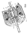
- Figure 3 is a perspective view of the bearing portion of the fan motor of the condenser unit.
- Figure 4 is a schematic illustration thereof.
- Figure 5 is a graphic illustration of pressures as maintained by the present invention.
- a heat pump system is shown to include a compressor 11 an indoor coil 12, an expansion device 13, and an outdoor coil 14.
- a 4-way, or reversing, valve 16 is provided to selectively direct the refrigerant flow to accommodate the respective cooling, heating, or defrost modes of operation. In all modes of operation, the compressor 11 draws refrigerant from the suction line 16 and discharges it to the discharge line 17.
- transducer 18 which is operatively connected to the discharge line 17.
- the transducer may be any of various types; however, one that has been found satisfactory is a 5 VDC high and low pressure transducer 8 PSIA-420 PSIG, which is commercially available from Texas Instruments Inc.
- the head pressure control board of the present invention is identified by numeral 19 in figures 1 and 2. This may be mounted on a partition in the fan deck area as shown in Figure 2.
- the control 19 is connected by its one lead 21 to a high voltage terminal L1, and by its other lead 22 to terminal L2, thru fan motor windings 23.
- Head pressure control 19 operates to selectively switch the power on and off to the fan motor windings 23 in response to sensed conditions in the system and in the ambient environment.
- Inputs to the head pressure control 19 include 24V AC power, which is provided along leads 27 and 28; the outputs from the transducer 18, which are provided along leads 29, 31 and 32; and the outputs from a thermister 33, which are provided by way of leads 34 and 36.
- the purpose of the thermister 33 is to sense the ambient temperature condition and either permit or preclude the operation of the head pressure control 19 as will be more fully described hereinafter.
- the head pressure control 19 responds quickly to turn off the power to the fan motor windings 23 by way of a solid state relay shown schematically at 37.
- the effect of this is to immediately cause the outdoor coil 14 to be less effective in its condensing function and to thereby increase the suction pressure and the discharge pressure.
- the transducer 18 senses the increased discharge pressure and causes the head pressure control 19 to responsively turn the power to the windings 23 back on by way of the solid state relay 37.
- This process will continue at a relatively rapid rate (i.e. full cycle every 10 seconds or so) for prolonged periods of time. It is therefore necessary to have a solid state relay 37 which can reliably operate in this manner on a long life basis.
- a solid state relay which has been found suitable for this purpose is one identified by Part No. SIR1A10A6 - which can be obtained commercially from SSAC Inc.
- the motor 38 shown in Figure 3 is one which has been found suitable for the present purpose. It is commercially available from General Electric Company under the model designation of KCP 39. Its rotor 39 is fixed to the shaft 41, which in turn is supported by way of a pair of spaced sleeve bearings 42. Oil slingers 43 and 44 are disposed on either side of the bearing 42 and a wick 46 is provided around the circumference of the bearing 42 in order to provide the continuous lubrication thereto as required. This structure and features can be more clearly seen by reference to Figure 4.
- the cylindrical sleeve bearing 42 has a rectangular window 47 formed therein.
- a feed wick 48 is disposed in the window 47 and provides fluid communication between the wick 46 and the shaft 41.
- the oil then passes from a storage reservoir 49, through the wick 46 and the feed wick 48 to be wiped onto the shaft 41. It is then carried around from a region of high clearance to low clearance developing sufficient pressure to float the shaft 41.
- the excess oil squeezes out the ends and is thrown centrifugally by the oil slingers 43 and 44 back into the storage reservoir 49. By capillary action, it is then returned to the feed wick 48 and the cycle is repeated.
- the operation of the air pressure control system will now be described. Assume that the system is operating with R-22 as the refrigerant, with an air cooled condenser at ambient conditions.
- the ambient temperature is sensed by the thermister 33, and if the temperature is above a predetermined threshold (e.g. 13°C (55°F)),then the head pressure control system of the present invention is automatically inactivated since, under those conditions, it is not necessary in order to keep the head pressure up.
- a desired discharge pressure e.g.
- 16 bar (210 psig)) is established. If the discharge pressure in the discharge line 17 drops below 16 bar (210 psig), then the fan motor 38 is cycled off, and if it rises above 16 bar (210 psig) then the fan motor 38 is cycled back on. When the fan motor is turned off, it causes the head pressure to again increase to the desired level, at which point the fan motor is then again turned on.
- the result is as shown in Figure 5, with the discharge pressure remaining close to 15.65 bar (205 psig) (i.e. plus or minus 0.36 bar (5 psig)) and the suction pressure remaining substantially constant at 6 bar (70 psig). This is desirable since a variation in the suction pressure can cause the expansion valve to hunt.
- the motor speed will drop down from its maximum of 800 rpm, but will not come to a complete stop even for off periods up to 10 seconds.
- the existence of an oil film between the bearing surface and the shaft 41 is maintained. That is, as the ambient temperature is decreased and the off periods are correspondingly increased, the motor rotor 39 tends to reduce its rotational speed and thus the amount of oil that is circulated over the shaft 41.
- the motor 38 will receive proper lubrication during this cycling process.
Landscapes
- Engineering & Computer Science (AREA)
- Power Engineering (AREA)
- Physics & Mathematics (AREA)
- Mechanical Engineering (AREA)
- Thermal Sciences (AREA)
- General Engineering & Computer Science (AREA)
- Air Conditioning Control Device (AREA)
- Control Of Positive-Displacement Air Blowers (AREA)
- Structures Of Non-Positive Displacement Pumps (AREA)
- Control Of Positive-Displacement Pumps (AREA)
Claims (17)
- Druckgefälle-Steuerung für eine Klimaanlage des Typs, der einen Kompressor (11), einen Verdampfer (12) und einen luftgekühlten Verflüssiger (14) mit einem durch einen Mocor (38) angetriebenen Ventilator hat, wobei die Druckgefälle-Steuerung umfasst:eine Einrichtung (33) zum Messen der Umgebungstemperatur,eine Einrichtung (18) zum Messen des Austrittsdruckes des Kompressors (11), undeine Einrichtung (19), um nacheinander den Strom zum Ventilatormotor (38) zwischen einer Ein und einer Aus Bedingung umzuschalten,dadurch gekennzeichnet, dass die Einrichtung (19) zum Umschalten reagiert, wenn gemessen wird, dass der Austrittsdruck unter einen einzigen vorgegebenen Schwellenwert fällt oder dass er über ihn ansteigt, unddadurch, dass die Umschalteinrichtung (19) nur wirksam ist, wenn, aufgrund einer vorgegebenen Abhängigkeit der Ein und Aus Perioden von der Umgebungstemperatur, erwartet wird, dass die Periode der Aus Bedingung grösser ist als die Periode der Ein Bedingung.
- Druckgefälle-Steuerung nach Anspruch 1, dadurch gekennzeichnet, dass die Umschaltvorrichtung (19) auf eine solche Art arbeitet, dass die Ein Periode bei höheren Umgebungstemperaturen anwächst.
- Druckgefälle-Steuerung nach Anspruch 1, dadurch gekennzeichnet, dass die Umschaltvorrichtung (19) auf eine solche Art arbeitet, dass die Aus Periode 10 Sekunden nicht überschreitet.
- System für eine Druckgefälle-Steuerung nach Anspruch 1, dadurch gekennzeichnet, dass der vorgegebene Wert im allgemeinen im Bereich von 15.65 Bar (205 psi) liegt.
- Druckgefälle-Steuerung nach Anspruch 1, dadurch gekennzeichnet, dass die Einrichtung (18) zum Messen des Austrittsdruckes einen Messwandler umfasst.
- Druckgefälle-Steuerung nach Anspruch 1, dadurch gekennzeichnet, dass die Umschalteinrichtung (19) ein monolithisches Relais (37) umfasst.
- Druckgefälle-Steuerung nach Anspruch 1, dadurch gekennzeichnet, dass die Umschalteinrichtung (19) nicht erlaubt, dass der Ventilatormotor (38) während dem Umschaltvorgang zu einem vollständigen Stillstand kommt.
- Druckgefälle-Steuerung nach Anspruch 1, dadurch gekennzeichnet, dass der Ventilatormotor (38) durch einfache Gleitlager (42) gestützt wird.
- Druckgefälle-Steuerung nach Anspruch 1, dadurch gekennzeichnet, dass die Druckgefälle-steuerung deaktiviert wird, wenn die Einrichtung (33) zum Messen der Temperatur das vorhandensein einer Umgebungstemperatur über einem vorgegebenen Niveau misst.
- Verfahren, um während Bedingungen mit tiefer Umgebungstemperatur ein Druckgefälle in einer Klimaanlage beizubehalten, die einen Kompressor (11), einen Verdampfer (12) und einen Verflüssiger (14) mit einem durch einen Motor (38) angetriebenen Ventilator hat, wobei das Verfahren die Schritte umfasst:die Umgebungstemperatur zu messen (33),kontinuierlich den Austrittsdruck des Kompressors (11) zu messen (18),abwechselnd Strom an den Ventilatormotor (38) zu liefern und zu entfernen (19),gekennzeichnet durch das Vergleichen des Austrittsdruckes mit einem einzigen vorgegebenen Schwellenwert,wobei der Schritt (19) des Lieferns und Entfernens von Strom nur dann auf das Überschreiten des einzigen vorgegebenen Schwellenwertes respektive das Darunterfallen durch den Austrittsdruck reagiert, wenn aufgrund einer vorgegebenen Abhängigkeit der Perioden, in welchen der Strom geliefert und entfernt wird, von der Umgebungstemperatur die Periode, in welcher der Strom entfernt wird, die Periode, in welcher der Strom an den Ventilatormotor (38) geliefert wird, übersteigt.
- Verfahren nach Anspruch 10, dadurch gekennzeichnet, dass der Schritt (19) des Lieferns und Entfernens von Strom mittels eines monolithischen Relais (37) zustande gebracht wird.
- Verfahren nach Anspruch 10, dadurch gekennzeichnet, dass der Schritt des Messens des Druckes mittels eines Messwandlers (18) zustande gebracht wird.
- Verfahren nach Anspruch 10, dadurch gekennzeichnet, dass die Periode, in welcher der Strom entfernt wird, 10 Sekunden nicht überschreitet.
- Verfahren nach Anspruch 10, dadurch gekennzeichnet, dass der vorgegebene Schwellenwert im allgemeinen bei einem Niveau von 15.65 Bar (205 psi) liegt.
- Verfahren nach Anspruch 10, dadurch gekennzeichnet, dass die Periode, in welcher der Strom zum Ventilatormotor (38) entfernt wird, begrenzt ist, damit es dem Ventilatormotor (38) nicht erlaubt wird, zu einem vollständigen Stillstand zu kommen.
- Verfahren nach Anspruch 10, dadurch gekennzeichnet, dass der Ventilatormotor (38) mit einfachen Gleitlagern (41) gestützt wird.
- Verfahren nach Anspruch 10, dadurch gekennzeichnet, dass es den zusätzlichen Schritt enthält:dem Vorgang nur zu erlauben, fortzuschreiten, wenn die gemessene Umgebungstemperatur unterhalb eines vorgegebenen Niveaus liegt.
Applications Claiming Priority (2)
| Application Number | Priority Date | Filing Date | Title |
|---|---|---|---|
| US07/670,815 US5247805A (en) | 1991-03-18 | 1991-03-18 | Fan cycling means of head pressure control |
| US670815 | 2000-09-28 |
Publications (3)
| Publication Number | Publication Date |
|---|---|
| EP0509952A2 EP0509952A2 (de) | 1992-10-21 |
| EP0509952A3 EP0509952A3 (en) | 1993-02-03 |
| EP0509952B1 true EP0509952B1 (de) | 1996-07-24 |
Family
ID=24691993
Family Applications (1)
| Application Number | Title | Priority Date | Filing Date |
|---|---|---|---|
| EP92630029A Expired - Lifetime EP0509952B1 (de) | 1991-03-18 | 1992-03-13 | Gebläsetaktsteuerung zur Einstellung der Verdichter-Förderhöhe |
Country Status (4)
| Country | Link |
|---|---|
| US (1) | US5247805A (de) |
| EP (1) | EP0509952B1 (de) |
| DE (1) | DE69212370T2 (de) |
| ES (1) | ES2091437T3 (de) |
Families Citing this family (13)
| Publication number | Priority date | Publication date | Assignee | Title |
|---|---|---|---|---|
| US5513361A (en) * | 1994-07-25 | 1996-04-30 | Intel Corporation | Method and apparatus for reducing power consumption of a fan in a computer system |
| US5628201A (en) * | 1995-04-03 | 1997-05-13 | Copeland Corporation | Heating and cooling system with variable capacity compressor |
| US5531076A (en) * | 1995-04-26 | 1996-07-02 | Carrier Corporation | Multi-split fan control |
| US5570586A (en) * | 1995-05-11 | 1996-11-05 | Carrier Corporation | Interface circuit for use in multi-split air conditioning systems |
| US5782101A (en) * | 1997-02-27 | 1998-07-21 | Carrier Corporation | Heat pump operating in the heating mode refrigerant pressure control |
| JP2001050599A (ja) | 1999-07-28 | 2001-02-23 | Johnson Controls Technol Co | ファン速度空冷凝縮器を高機能制御する装置および方法 |
| DE10016940A1 (de) * | 2000-04-05 | 2001-10-11 | Linde Ag | Verfahren zum Betreiben eines mehrstufig luftgekühlten Verflüssigers und mehrstufig luftgekühlter Verflüssiger |
| US6907745B2 (en) | 2003-06-26 | 2005-06-21 | Carrier Corporation | Heat pump with improved performance in heating mode |
| US7263848B2 (en) * | 2005-08-24 | 2007-09-04 | Delphi Technologies, Inc. | Heat pump system |
| US20100236262A1 (en) * | 2007-11-08 | 2010-09-23 | Carrier Corporation | Method and apparatus for improving dehumidification |
| US9297567B2 (en) | 2009-01-30 | 2016-03-29 | National Refrigeration & Air Conditioning Canada Corp. | Condenser assembly with a fan controller and a method of operating same |
| US9109830B2 (en) | 2010-08-11 | 2015-08-18 | Mitsubishi Electric Corporation | Low ambient cooling kit for variable refrigerant flow heat pump |
| US9989289B2 (en) | 2013-02-12 | 2018-06-05 | National Refrigeration & Air Conditioning Corp. | Condenser unit |
Citations (4)
| Publication number | Priority date | Publication date | Assignee | Title |
|---|---|---|---|---|
| US3112620A (en) * | 1962-03-29 | 1963-12-03 | Westinghouse Electric Corp | Controls for refrigeration systems having air cooled condensers |
| US3354665A (en) * | 1966-12-01 | 1967-11-28 | Trane Co | Condenser fan speed control |
| US3792592A (en) * | 1972-06-30 | 1974-02-19 | Ranco Inc | Cold weather starting control means for refrigerating systems |
| US4590772A (en) * | 1983-10-07 | 1986-05-27 | Nissan Motor Co., Ltd. | Air conditioning system for vehicle |
Family Cites Families (4)
| Publication number | Priority date | Publication date | Assignee | Title |
|---|---|---|---|---|
| US312620A (en) * | 1885-02-24 | Josiah w | ||
| US2943457A (en) * | 1959-03-13 | 1960-07-05 | Recold Corp | Control system for winter operation of air-cooled condensers |
| US3613391A (en) * | 1967-09-12 | 1971-10-19 | White Consolidated Ind Inc | Head pressure control system |
| US4507933A (en) * | 1980-05-05 | 1985-04-02 | Roman Chapa | System combining water heater and refrigeration unit |
-
1991
- 1991-03-18 US US07/670,815 patent/US5247805A/en not_active Expired - Lifetime
-
1992
- 1992-03-13 DE DE69212370T patent/DE69212370T2/de not_active Expired - Fee Related
- 1992-03-13 EP EP92630029A patent/EP0509952B1/de not_active Expired - Lifetime
- 1992-03-13 ES ES92630029T patent/ES2091437T3/es not_active Expired - Lifetime
Patent Citations (4)
| Publication number | Priority date | Publication date | Assignee | Title |
|---|---|---|---|---|
| US3112620A (en) * | 1962-03-29 | 1963-12-03 | Westinghouse Electric Corp | Controls for refrigeration systems having air cooled condensers |
| US3354665A (en) * | 1966-12-01 | 1967-11-28 | Trane Co | Condenser fan speed control |
| US3792592A (en) * | 1972-06-30 | 1974-02-19 | Ranco Inc | Cold weather starting control means for refrigerating systems |
| US4590772A (en) * | 1983-10-07 | 1986-05-27 | Nissan Motor Co., Ltd. | Air conditioning system for vehicle |
Also Published As
| Publication number | Publication date |
|---|---|
| DE69212370T2 (de) | 1997-01-30 |
| EP0509952A3 (en) | 1993-02-03 |
| DE69212370D1 (de) | 1996-08-29 |
| ES2091437T3 (es) | 1996-11-01 |
| EP0509952A2 (de) | 1992-10-21 |
| US5247805A (en) | 1993-09-28 |
Similar Documents
| Publication | Publication Date | Title |
|---|---|---|
| US5054294A (en) | Compressor discharge temperature control for a variable speed compressor | |
| US5247805A (en) | Fan cycling means of head pressure control | |
| US5257506A (en) | Defrost control | |
| US5782101A (en) | Heat pump operating in the heating mode refrigerant pressure control | |
| KR101498689B1 (ko) | 밀폐 모터 냉각 및 제어 | |
| US5950439A (en) | Methods and systems for controlling a refrigeration system | |
| US4286438A (en) | Condition responsive liquid line valve for refrigeration appliance | |
| US4484449A (en) | Low temperature fail-safe cascade cooling apparatus | |
| US9151525B2 (en) | Method of operating an evaporator assembly with a fan controller | |
| US3913342A (en) | Motor compressor control | |
| EP0158582A2 (de) | Zweifach-Absaugung zum Schützen eines Verdichters in einem Kältesystem | |
| EP1156213B1 (de) | Verdichteranlage mit einem gesteuerten Kühlventilator | |
| WO2009096620A1 (en) | A method and an apparatus for protecting a compressor of an air-conditioning system | |
| US6263686B1 (en) | Defrost control method and apparatus | |
| US3577741A (en) | Refrigeration apparatus | |
| KR20040103487A (ko) | 냉각 장치 | |
| US5179841A (en) | Heat reclamation from and adjustment of defrost cycle | |
| EP0654370B1 (de) | Verfahren und Vorrichtung zur Vermeidung der Bildung von kondensiertem Wasserdampf in Klimaanlagen | |
| KR900001357B1 (ko) | 냉동사이클의 능력 제어장치 | |
| JPH10148405A (ja) | 冷凍・空気調和機 | |
| US3791161A (en) | Pressure switch for refrigeration system | |
| JP4379978B2 (ja) | コンプレッサ起動制御装置 | |
| JP4326274B2 (ja) | 冷凍回路 | |
| JP3134885B2 (ja) | 車両用空調装置 | |
| JPH09287861A (ja) | 冷蔵庫の運転制御装置 |
Legal Events
| Date | Code | Title | Description |
|---|---|---|---|
| PUAI | Public reference made under article 153(3) epc to a published international application that has entered the european phase |
Free format text: ORIGINAL CODE: 0009012 |
|
| AK | Designated contracting states |
Kind code of ref document: A2 Designated state(s): DE ES FR IT |
|
| PUAL | Search report despatched |
Free format text: ORIGINAL CODE: 0009013 |
|
| AK | Designated contracting states |
Kind code of ref document: A3 Designated state(s): DE ES FR IT |
|
| 17P | Request for examination filed |
Effective date: 19930707 |
|
| 17Q | First examination report despatched |
Effective date: 19940317 |
|
| GRAH | Despatch of communication of intention to grant a patent |
Free format text: ORIGINAL CODE: EPIDOS IGRA |
|
| GRAH | Despatch of communication of intention to grant a patent |
Free format text: ORIGINAL CODE: EPIDOS IGRA |
|
| GRAA | (expected) grant |
Free format text: ORIGINAL CODE: 0009210 |
|
| AK | Designated contracting states |
Kind code of ref document: B1 Designated state(s): DE ES FR IT |
|
| REF | Corresponds to: |
Ref document number: 69212370 Country of ref document: DE Date of ref document: 19960829 |
|
| ET | Fr: translation filed | ||
| ITF | It: translation for a ep patent filed | ||
| REG | Reference to a national code |
Ref country code: ES Ref legal event code: FG2A Ref document number: 2091437 Country of ref document: ES Kind code of ref document: T3 |
|
| PG25 | Lapsed in a contracting state [announced via postgrant information from national office to epo] |
Ref country code: ES Free format text: LAPSE BECAUSE OF NON-PAYMENT OF DUE FEES Effective date: 19970314 |
|
| PLBE | No opposition filed within time limit |
Free format text: ORIGINAL CODE: 0009261 |
|
| 26N | No opposition filed | ||
| PG25 | Lapsed in a contracting state [announced via postgrant information from national office to epo] |
Ref country code: FR Free format text: LAPSE BECAUSE OF NON-PAYMENT OF DUE FEES Effective date: 19971128 |
|
| PG25 | Lapsed in a contracting state [announced via postgrant information from national office to epo] |
Ref country code: DE Effective date: 19971202 |
|
| REG | Reference to a national code |
Ref country code: FR Ref legal event code: ST |
|
| REG | Reference to a national code |
Ref country code: ES Ref legal event code: FD2A Effective date: 20010503 |
|
| PG25 | Lapsed in a contracting state [announced via postgrant information from national office to epo] |
Ref country code: IT Free format text: LAPSE BECAUSE OF NON-PAYMENT OF DUE FEES;WARNING: LAPSES OF ITALIAN PATENTS WITH EFFECTIVE DATE BEFORE 2007 MAY HAVE OCCURRED AT ANY TIME BEFORE 2007. THE CORRECT EFFECTIVE DATE MAY BE DIFFERENT FROM THE ONE RECORDED. Effective date: 20050313 |