EP0509577A1 - Optischer Verstärker mit aktiver Faser für faseroptische Nachrichtenübertragungsleitung - Google Patents
Optischer Verstärker mit aktiver Faser für faseroptische Nachrichtenübertragungsleitung Download PDFInfo
- Publication number
- EP0509577A1 EP0509577A1 EP92200936A EP92200936A EP0509577A1 EP 0509577 A1 EP0509577 A1 EP 0509577A1 EP 92200936 A EP92200936 A EP 92200936A EP 92200936 A EP92200936 A EP 92200936A EP 0509577 A1 EP0509577 A1 EP 0509577A1
- Authority
- EP
- European Patent Office
- Prior art keywords
- upstream
- active fiber
- downstream
- optical
- fiber
- Prior art date
- Legal status (The legal status is an assumption and is not a legal conclusion. Google has not performed a legal analysis and makes no representation as to the accuracy of the status listed.)
- Granted
Links
- 239000000835 fiber Substances 0.000 title claims abstract description 168
- 230000003287 optical effect Effects 0.000 title claims abstract description 57
- 238000011144 upstream manufacturing Methods 0.000 claims abstract description 94
- 238000005086 pumping Methods 0.000 claims abstract description 29
- 239000002019 doping agent Substances 0.000 claims abstract description 21
- 239000013307 optical fiber Substances 0.000 claims abstract description 21
- 239000012212 insulator Substances 0.000 claims abstract description 15
- 238000002310 reflectometry Methods 0.000 claims description 22
- 230000005540 biological transmission Effects 0.000 claims description 13
- 238000009792 diffusion process Methods 0.000 claims description 5
- 238000000034 method Methods 0.000 claims description 5
- 229910052691 Erbium Inorganic materials 0.000 claims description 4
- UYAHIZSMUZPPFV-UHFFFAOYSA-N erbium Chemical compound [Er] UYAHIZSMUZPPFV-UHFFFAOYSA-N 0.000 claims description 4
- 230000000295 complement effect Effects 0.000 claims description 2
- 230000002269 spontaneous effect Effects 0.000 description 7
- 230000003321 amplification Effects 0.000 description 5
- 238000003199 nucleic acid amplification method Methods 0.000 description 5
- 230000005283 ground state Effects 0.000 description 4
- 238000010276 construction Methods 0.000 description 3
- 229910052732 germanium Inorganic materials 0.000 description 3
- GNPVGFCGXDBREM-UHFFFAOYSA-N germanium atom Chemical compound [Ge] GNPVGFCGXDBREM-UHFFFAOYSA-N 0.000 description 3
- 230000035945 sensitivity Effects 0.000 description 3
- XUIMIQQOPSSXEZ-UHFFFAOYSA-N Silicon Chemical compound [Si] XUIMIQQOPSSXEZ-UHFFFAOYSA-N 0.000 description 2
- 230000007423 decrease Effects 0.000 description 2
- 230000000694 effects Effects 0.000 description 2
- VQCBHWLJZDBHOS-UHFFFAOYSA-N erbium(III) oxide Inorganic materials O=[Er]O[Er]=O VQCBHWLJZDBHOS-UHFFFAOYSA-N 0.000 description 2
- 230000005281 excited state Effects 0.000 description 2
- 238000003780 insertion Methods 0.000 description 2
- 230000037431 insertion Effects 0.000 description 2
- 150000002500 ions Chemical class 0.000 description 2
- 229910052710 silicon Inorganic materials 0.000 description 2
- 239000010703 silicon Substances 0.000 description 2
- XAGFODPZIPBFFR-UHFFFAOYSA-N aluminium Chemical compound [Al] XAGFODPZIPBFFR-UHFFFAOYSA-N 0.000 description 1
- 229910052782 aluminium Inorganic materials 0.000 description 1
- 230000002238 attenuated effect Effects 0.000 description 1
- 230000001427 coherent effect Effects 0.000 description 1
- 230000001143 conditioned effect Effects 0.000 description 1
- 230000003247 decreasing effect Effects 0.000 description 1
- 238000010586 diagram Methods 0.000 description 1
- 230000005284 excitation Effects 0.000 description 1
- 239000011521 glass Substances 0.000 description 1
- 239000003607 modifier Substances 0.000 description 1
- 230000000750 progressive effect Effects 0.000 description 1
- 230000001902 propagating effect Effects 0.000 description 1
- 230000008054 signal transmission Effects 0.000 description 1
Images
Classifications
-
- H—ELECTRICITY
- H01—ELECTRIC ELEMENTS
- H01S—DEVICES USING THE PROCESS OF LIGHT AMPLIFICATION BY STIMULATED EMISSION OF RADIATION [LASER] TO AMPLIFY OR GENERATE LIGHT; DEVICES USING STIMULATED EMISSION OF ELECTROMAGNETIC RADIATION IN WAVE RANGES OTHER THAN OPTICAL
- H01S3/00—Lasers, i.e. devices using stimulated emission of electromagnetic radiation in the infrared, visible or ultraviolet wave range
- H01S3/05—Construction or shape of optical resonators; Accommodation of active medium therein; Shape of active medium
- H01S3/06—Construction or shape of active medium
- H01S3/063—Waveguide lasers, i.e. whereby the dimensions of the waveguide are of the order of the light wavelength
- H01S3/067—Fibre lasers
- H01S3/06754—Fibre amplifiers
- H01S3/06758—Tandem amplifiers
Definitions
- This invention relates to an active fiber optical amplifier for a fiber optics telecommunication line through which a signal is caused to pass in a predetermined direction.
- fiber optics telecommunication lines wherein the transmission signal is a suitably modulated light signal guided through optical fibers; such lines are valued especially because of their ability to transmit a signal over great distances with low attenuation.
- the signal may have to be amplified; such amplifications can be either provided by repeaters or optical amplifiers.
- the optical signal would be converted into a different, usually electric, form which is then amplified, as by electronic apparatus, and converted back into a light signal; this is the simpler method, but also one that introduces transmission rate limitations due to the signal transmission rate being conditioned by the processing rate of the amplifying apparatus employed.
- the telecommunication light signal would be amplified as it is, namely in the optical form.
- a so-called “active” fiber section is provided by adding suitable dopants to an optical fiber; into this active fiber, so-called “pumping” luminous energy is supplied, which has a shorter wavelength than the signal and excites the electrons of the dopants present in the fiber to a lasing level.
- the passage of a signal at a wavelength corresponding to said lasing level is apt to cause the decay from said lasing level to the ground state of the dopant electrons, with an associated coherent light emission, thereby amplifying the signal.
- the pumping energy is usually provided by a laser source, injected into an optical fiber, and inserted into the fiber that carries the signal by means of a dichroic coupler (or optical multiplexer). Within the active fiber, the pumping energy propagates with progressive attenuation of its luminous power along the fiber, mainly due to energy being transferred to the dopants, exciting them to the lasing level.
- the minimum luminous power required at each section of the active fiber to produce amplification gain is referred to as the threshold power; above this level, there would occur a so-called reversal of population among the dopant atoms, meaning that the number of the atoms in the excited lasing level would be larger than the number of the atoms in the ground, unexcited state.
- the probability of the signal photons meeting with an excited atom and, accordingly, generating a second photon is higher than the probability that the photons meet with an atom in the ground state and are absorbed thereby (with excitation of the atom to an higher level).
- the outcome of this is a gain in the signal which is the higher the greater is the number of the atoms in the lasing state, i.e. the more complete is the population inversion.
- the desired amplifying effect is always accompanied by an undesired effect of noise introduction.
- This may originate essentially as noise from random-type light emissions in the line, or be due to signal attenuation brought about by components being connected in the line (insertion attenuations), which would lower the level of the signal relatively to the noise and thus make the weight of the latter more important.
- a first cause of disturbance is associated with the spontaneous emission from the active fiber showing up when its atoms are in the excited state; in fact, after a time delay, the excited dopant atoms decay spontaneously to the ground state from the lasing level, emitting a photon.
- the diffused random brightness thus generated constitutes noise affecting a signal being transmitted.
- This noise intensity increases with population inversion, i.e. as the number of atoms in the excited state increases; it has been found, however, that as inversion decreases, the noise due to spontaneous emission decreases at a lower rate than gain.
- interferometric noise Another type of noise generated in active fiber amplifiers is the so-called interferometric noise, which is due to beats occurring between the forward signal and reflected signals within one fiber; such signals are typically caused by discontinuity surfaces (which can be avoided or at least limited) but also by unavoidable (Rayleigh's, Brillouin's) scattering phenomena taking place within the fiber itself.
- optical isolators In order to prevent the reflected signals from propagating, and hence subdue interferometric noise, the use of so-called optical isolators has been proposed which only admit the signals in one direction. See on the subject Italian Patent Application No. 20434-A/90 (EP application N°91108162.8) by this same Applicant.
- This invention relates to an active fiber optical amplifier for a fiber optics telecommunication line through which a signal is caused to pass in a predetermined direction, of the type comprising an active fiber doped with a fluorescent dopant and an optical coupler through which pumping luminous energy is fed into the active fiber, characterized in that it comprises an upstream amplifying stage and a downstream amplifying stage, consecutively connected along the line in the direction of the transmission signal, in which the upstream amplifying stage comprises an upstream active fiber doped with a fluorescent dopant and connected serially to the optical fiber line, an upstream optical coupler connected serially downstream from the upstream active fiber, means for supplying pumping energy towards the upstream active fiber through the coupler, said coupler being oriented to cause pump energy travel towards said upstream active fiber in the opposite direction from the predetermined signal direction, and the downstream amplifying stage comprises a downstream active fiber doped with a flourescent dopant and connected serially in the optical fiber, a downstream optical coupler connected serially in the downstream active fiber, means of
- an upstream stage where the transmission signal is introduced into the amplifying fiber with no attenuation and the signal is only amplified to a limited extent allows the downstream stage to be input a signal which is at a sufficiently high level to be amplified to the desired value with negligible noise; stated otherwise, in assessing the overall noise of the amplifier, the contribution from the attenuations due to the discrete elements (couplers, isolators) present is reduced by a factor equal to the active fiber gain.
- the noise generated upstream in the active fiber comprises both the interferometric noise component and the noise component from spontaneous decay of the excited dopant atoms; whereas interferometric noise is proportional to the fourth power of the gain in the active fiber, the noise from spontaneous decay is proportional to the degree of inversion in the population of dopant atoms.
- the optical coupler can be oriented so that the pumping energy is supplied into the downstream active fiber, either in the same direction as the signal, or in the opposite direction, or even in both directions.
- the coupler would be positioned upstream of the active fiber; in the latter case, the coupler would be positioned between the active fiber and the upstream insulator.
- the pumping energy supply direction of choice runs instead opposite from that of the transmission signal because the noise from the attenuation due to the coupler being connected in would be then attenuated by a factor equal to the gain in the active fiber itself, as would all noises downstream from said upstream active fiber; in other words, no attenuating elements are introduced at a location where the signal is at its lowest level.
- the gain of the upstream active fiber is below a predetermined maximum value, such that the interferometric noise in the upstream active fiber can be made negligible, and above a minimum value whereby the contribution to the overall noise figure of the amplifier from the combined noise figure of the components downstream from the upstream section of active fiber will be less than 1/10 the noise figure of the upstream section of the active fiber.
- the predetermined maximum value is 100 times lower than the geometric mean of the reflectivities upstream and downstream from the upstream section of active fiber. Still more preferably, the predetermined maximum value is 100 times lower than the geometric mean of the reflectivity due to Rayleigh's diffusion through the line fiber upstream of the upstream section of active fiber, and the reflectivity of the downstream insulator toward the active fiber.
- Gain values within the range of 8 to 15 dB are preferred.
- the present invention relates to a method for amplifying an optical signal in a fiber optics telecommunication line, through which a signal is caused to pass in a predetermined direction, by means of an optical active fiber amplifier, which comprises the steps of:
- Preferably said predetermined maximum value is 100 times lower than the geometric mean of the reflectivities upstream and downstream of the upstream active fiber.
- More preferably said predetermined maximum value is 100 times lower than the geometric mean of the reflectivity from Rayleigh's diffusion through the line fiber upstream of the upstream active fiber and the reflectivity of the downstream amplifying stage toward the upstream active fiber.
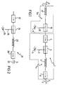
- An optical amplifier 1 embodying this invention is connected serially in an optical fiber 2, also referred to herein as line fiber, through which an optical transmission signal is driven in a predetermined direction, from left to right in the diagram as indicated by arrows S.
- the amplifier 1 comprises a downstream section of active fiber 3, also referred to herein as downstream active fiber, which connects serially to the line fiber 2, and a downstream dichroic coupler 4 connected serially in the optical fiber 2 upstream of the downstream active fiber section 3.
- the active fiber 3 is fed, via the coupler 4 and in the same direction as the signal, a luminous pumping energy with an appropriate wavelength which is supplied from a suitable supply means 5.
- First and second optical isolators, 7 and 8, are connected serially in the fiber 2, respectively upstream of, and downstream from, the downstream active fiber 3.
- the active fiber 3, coupler 4, pumping means 5, and insulators 7, 8 jointly form a downstream amplifying stage S V .
- the amplifier 1 comprises an upstream section of active fiber 9, also referred to herein as upstream active fiber, which is connected serially in the optical fiber 2, at a location upstream of the first isolator 7, and an upstream dichroic coupler 10, which is connected serially in the optical fiber 2 between the upstream active fiber 9 and the first isolator 7.
- upstream active fiber also referred to herein as upstream active fiber
- upstream dichroic coupler 10 which is connected serially in the optical fiber 2 between the upstream active fiber 9 and the first isolator 7.
- the upstream active fiber 9 is fed, in the opposite direction from the signal direction, a luminous pumping energy with a suitable wavelength, being supplied by a suitable supply means 11. No insulator is provided upstream of active fiber 9.
- the active fiber 9, coupler 10, and pumping means 11 jointly form an upstream amplifying stage S M .
- the active optical fibers, 3 and 9, of the two amplifying stages are optical fibers which are core doped with a refractive index modifier, such as germanium or aluminum, to obtain a desired profile for the refractive indices, and which are made "active" by the added presence of a fluorescent dopant, preferably erbium, in the core.
- a refractive index modifier such as germanium or aluminum
- Fibers of the type described above are known in the art, e.g. from the aforementioned prior patents.
- the luminous pumping energy supply means, 5 and 11, consist preferably of conventional laser diodes of suitable power which connect to their respective couplers, 4 and 10, through respective optical fiber sections, 6 and 12.
- optical couplers 4 and 10 comprise, of preference, conventional fused fiber couplers, not further described herein.
- the pumping powers supplied into the downstream and upstream fiber sections are to maintain a higher power than threshold power at the section more remote from the coupler, that is to maintain a state of complete population inversion in the fibers.
- N A N AM + N AV / (A acc A is G M )
- N AM and N AV are the noises generated in the upstream and downstream active fibers 9 and 3, respectively
- a acc is the sum of the attenuations of couplers 10 and 4
- A is is the attenuation of isolator 7
- G M is the gain of the upstream active fiber 9.
- optical couplers such as optical couplers, isolators, etc.
- optical couplers such as optical couplers, isolators, etc.
- N AMdec n sp h v (G M - 1) / G M
- N AMinterf H G M 4 R i R o
- n sp the degree of inversion in the upstream active fiber 9
- h Planck's constant
- v the frequency of the light signal
- H a constant
- R i and R o the reflectivity values at the input and output ends of active fiber 9.
- Noise figure is a quantity, well known in the art, which may be defined as the ratio of the overall noise power at the output of a system to the power of the input noise to the system.
- the optical isolator 7 located directly downstream from the upstream active fiber section 9 has a limited reflectivity toward section 9 at the wavelength of the transmission signal, preferably exceeding the reflectivity from Rayleigh's scattering through the line optical fiber 2 by no more than 10 dB.
- a typical value for reflectivity from Rayleigh's scattering through a line fiber is approximately 30 dB, and optical insulator 7 may have a reflectivity of 40 dB toward active fiber 9.
- Equation (VII) shows that amplifier 1 affords high gain with a minimum of noise.
- optical couplers, 4 and 10 are preferably fused fiber couplers.
- the length of the upstream section of active fiber 9, when combined with the pumping power specified and the amount of dopant present therein, is selected to give a gain of 10 dB; the length of the downstream active fiber section 3 is selected to provide a gain of 28 dB, thereby the overall gain of the amplifier 1 is 38 dB.
- the amplifier 21, which is connected serially in a line optical fiber 22, comprises a single active fiber section 23 and a dichroic coupler 24 connected serially along the fiber 22, upstream of the active fiber section 23.
- the active fiber 23 is fed, in the same direction as the signal, a pumping energy supplied by a laser diode 25 on an optical fiber 26 connected to the coupler.
- First and second optical insulators, 27 and 28, are connected serially in the fiber 22, respectively upstream of and downstream from the active fiber 23.
- Optical coupler 24 is a fused fiber one having an attenuation of 1 dB.
- Optical coupler 27 has an attenuation of 1.5 dB.
- the structure of this invention avoids the introduction of passive components before the signal has undergone a first amplification, by virtue of coupler 10 being located downstream from the active fiber 9; this solution, which in a conventional amplifier would entail in itself a decreased gain for a given pumping power over the traditional approach providing the optical coupler upstream of the active fiber, has been selected because the amplifying stage S M including fiber 9 performs essentially the function of reducing noise, and its gain does not limit the performance of the amplifier as a whole.
- stage S v which provides the remainder of the gain and is designed and sized to suit this purpose; it has preferably the construction shown, although to meet particular applicational requirements it could also include additional elements, such as means of reflecting the pumping power, a second pumping means to operate in the opposite direction from coupler 4 and laser diode 5 and the like.
Landscapes
- Physics & Mathematics (AREA)
- Electromagnetism (AREA)
- Engineering & Computer Science (AREA)
- Plasma & Fusion (AREA)
- Optics & Photonics (AREA)
- Lasers (AREA)
- Optical Communication System (AREA)
- Light Guides In General And Applications Therefor (AREA)
Applications Claiming Priority (2)
| Application Number | Priority Date | Filing Date | Title |
|---|---|---|---|
| ITMI911029A IT1246599B (it) | 1991-04-15 | 1991-04-15 | Amplificatore ottico a fibra attiva per una linea di telecomunicazione a fibra ottica |
| ITMI911029 | 1991-04-15 |
Publications (2)
| Publication Number | Publication Date |
|---|---|
| EP0509577A1 true EP0509577A1 (de) | 1992-10-21 |
| EP0509577B1 EP0509577B1 (de) | 1996-11-13 |
Family
ID=11359597
Family Applications (1)
| Application Number | Title | Priority Date | Filing Date |
|---|---|---|---|
| EP92200936A Expired - Lifetime EP0509577B1 (de) | 1991-04-15 | 1992-04-02 | Optischer Verstärker mit aktiver Faser für faseroptische Nachrichtenübertragungsleitung |
Country Status (5)
| Country | Link |
|---|---|
| EP (1) | EP0509577B1 (de) |
| CA (1) | CA2064647C (de) |
| DE (1) | DE69215131T2 (de) |
| ES (1) | ES2097267T3 (de) |
| IT (1) | IT1246599B (de) |
Cited By (4)
| Publication number | Priority date | Publication date | Assignee | Title |
|---|---|---|---|---|
| EP0613221A3 (de) * | 1993-02-26 | 1995-01-11 | Sel Alcatel Ag | Mehrstufiger faseroptischer Verstärker. |
| EP0647000A1 (de) * | 1993-09-30 | 1995-04-05 | AT&T Corp. | Zweistufiger, rauscharmer optischer Hochleistungsverstärker mit hoher Verstärkung |
| GB2315361A (en) * | 1996-07-15 | 1998-01-28 | Samsung Electronics Co Ltd | Erbium doped fibre amplifier |
| US6332722B1 (en) | 1997-08-04 | 2001-12-25 | Pirelli Cavi E Sistemi S.P.A. | Method for optically connecting optical components in an optoelectronic rig, and optoelectronic rig constructed according to this method |
-
1991
- 1991-04-15 IT ITMI911029A patent/IT1246599B/it active IP Right Grant
-
1992
- 1992-04-01 CA CA002064647A patent/CA2064647C/en not_active Expired - Fee Related
- 1992-04-02 DE DE69215131T patent/DE69215131T2/de not_active Expired - Fee Related
- 1992-04-02 ES ES92200936T patent/ES2097267T3/es not_active Expired - Lifetime
- 1992-04-02 EP EP92200936A patent/EP0509577B1/de not_active Expired - Lifetime
Non-Patent Citations (6)
| Title |
|---|
| ELECTRONICS LETTERS. vol. 25, no. 20, 28 September 1989, STEVENAGE GB pages 1393 - 1394; J.L GIMLETT ET AL.: 'Impact of multiple reflection noise in Gbit/s lightwave systems with optical fibre amplifiers' * |
| ELECTRONICS LETTERS. vol. 26, no. 10, 1 May 1990, STEVENAGE GB pages 661 - 662; H. MASUDA ET AL.: 'High gain two-stage amplification with erbium-doped fibre amplifier' * |
| IEEE PHOTONICS TECHNOLOGY LETTERS vol. 2, no. 12, December 1990, NEW YORK, US pages 866 - 868; C.R. GILES AT AL.: 'Dynamic gain equalization in two-stage fiber amplifiers' * |
| IEEE PHOTONICS TECHNOLOGY LETTERS vol. 3, no. 3, March 1991, NEW YORK, US pages 253 - 255; R.L. LAMING ET AL.: 'High power erbium-doped-fiber amplifiers operated in the saturated regime' * |
| OPTICS COMMUNICATIONS vol. 81, no. 1/2, 1 February 1991, AMSTERDAM, NL pages 23 - 26; B. PEDERSEN ET AL.: 'Erbium-doped fibre amplifier: efficient pumping at 807 nm' * |
| TECHNICAL DIGEST SERIES, OPTICAL AMPLIFIERS AND THEIR APPLICATIONS vol. 13, 1990, WASHINGTON D.C., US pages 126 - 129; T. KAKINUMA ET AL.: 'Gain and noise characteristics of Er-doped fiber amplifiers with different pumping directions' * |
Cited By (7)
| Publication number | Priority date | Publication date | Assignee | Title |
|---|---|---|---|---|
| EP0613221A3 (de) * | 1993-02-26 | 1995-01-11 | Sel Alcatel Ag | Mehrstufiger faseroptischer Verstärker. |
| US5506723A (en) * | 1993-02-26 | 1996-04-09 | Alcatel N.V. | Multistage fiber-optic amplifier |
| EP0647000A1 (de) * | 1993-09-30 | 1995-04-05 | AT&T Corp. | Zweistufiger, rauscharmer optischer Hochleistungsverstärker mit hoher Verstärkung |
| AU679098B2 (en) * | 1993-09-30 | 1997-06-19 | At & T Corporation | High power, high gain, two-stage optical amplifiers |
| GB2315361A (en) * | 1996-07-15 | 1998-01-28 | Samsung Electronics Co Ltd | Erbium doped fibre amplifier |
| GB2315361B (en) * | 1996-07-15 | 2000-05-10 | Samsung Electronics Co Ltd | Erbium doped fibre amplifier |
| US6332722B1 (en) | 1997-08-04 | 2001-12-25 | Pirelli Cavi E Sistemi S.P.A. | Method for optically connecting optical components in an optoelectronic rig, and optoelectronic rig constructed according to this method |
Also Published As
| Publication number | Publication date |
|---|---|
| CA2064647C (en) | 2000-02-08 |
| IT1246599B (it) | 1994-11-24 |
| ITMI911029A0 (it) | 1991-04-15 |
| DE69215131D1 (de) | 1996-12-19 |
| DE69215131T2 (de) | 1997-05-22 |
| ES2097267T3 (es) | 1997-04-01 |
| ITMI911029A1 (it) | 1992-10-15 |
| EP0509577B1 (de) | 1996-11-13 |
| CA2064647A1 (en) | 1992-10-16 |
Similar Documents
| Publication | Publication Date | Title |
|---|---|---|
| JP2971561B2 (ja) | エルビウム ドープ ファイバー増幅器 | |
| EP0567941B1 (de) | Optische Leistung begrenzender Verstärker | |
| US5253104A (en) | Balanced optical amplifier | |
| EP0789433B1 (de) | In Gegenrichtung gepumpter faseroptischer Ramanverstärker und dessen Anwendung in faseroptischem Kommunikationssystem | |
| US5375010A (en) | Optical amplifier | |
| EP0470497B1 (de) | Lichtverstärker mit optischer Faser | |
| JP3325887B2 (ja) | 光導波体増幅器 | |
| US5233463A (en) | Active fiber optical amplifier for a fiber optics telecommunication line | |
| JPH09318981A (ja) | 光ファイバラマン増幅器を含む装置 | |
| CN1323458A (zh) | 在光放大器中控制和利用放大自发发射 | |
| AU698168B2 (en) | Hybrid fiber amplifier | |
| EP1246320B1 (de) | Thulium-dotierter Faserverstärker | |
| CA2042697C (en) | Fiber optic amplifier | |
| Lewis et al. | Broadband high gain dispersion compensating Raman amplifier | |
| KR100326039B1 (ko) | 흡수체를갖는광증폭기 | |
| EP0509577B1 (de) | Optischer Verstärker mit aktiver Faser für faseroptische Nachrichtenübertragungsleitung | |
| US6421171B1 (en) | L-band optical fiber amplifier | |
| JPH09138432A (ja) | 光増幅器 | |
| US6914915B2 (en) | Optical fiber amplifier that can attain sufficient gain shift effect, small noise property and high operation efficiency at the same time even in two-wavelength excitation tm dopant optical fiber amplifier, and optical amplifier having the same | |
| Lewis et al. | Low-noise high gain dispersion compensating broadband Raman amplifier | |
| JPH09326519A (ja) | 広帯域光ファイバ増幅器 | |
| CN100385752C (zh) | 掺铒光纤 | |
| US6650400B2 (en) | Optical fibre amplifiers | |
| JP3361409B2 (ja) | 光ファイバ増幅器 | |
| JPH0486728A (ja) | エルビウムドープ光ファイバ増幅器 |
Legal Events
| Date | Code | Title | Description |
|---|---|---|---|
| PUAI | Public reference made under article 153(3) epc to a published international application that has entered the european phase |
Free format text: ORIGINAL CODE: 0009012 |
|
| AK | Designated contracting states |
Kind code of ref document: A1 Designated state(s): DE ES FR GB |
|
| 17P | Request for examination filed |
Effective date: 19930319 |
|
| 17Q | First examination report despatched |
Effective date: 19931208 |
|
| RAP1 | Party data changed (applicant data changed or rights of an application transferred) |
Owner name: PIRELLI CAVI S.P.A. |
|
| GRAG | Despatch of communication of intention to grant |
Free format text: ORIGINAL CODE: EPIDOS AGRA |
|
| GRAH | Despatch of communication of intention to grant a patent |
Free format text: ORIGINAL CODE: EPIDOS IGRA |
|
| GRAH | Despatch of communication of intention to grant a patent |
Free format text: ORIGINAL CODE: EPIDOS IGRA |
|
| GRAA | (expected) grant |
Free format text: ORIGINAL CODE: 0009210 |
|
| AK | Designated contracting states |
Kind code of ref document: B1 Designated state(s): DE ES FR GB |
|
| REF | Corresponds to: |
Ref document number: 69215131 Country of ref document: DE Date of ref document: 19961219 |
|
| ET | Fr: translation filed | ||
| REG | Reference to a national code |
Ref country code: ES Ref legal event code: FG2A Ref document number: 2097267 Country of ref document: ES Kind code of ref document: T3 |
|
| PLBE | No opposition filed within time limit |
Free format text: ORIGINAL CODE: 0009261 |
|
| STAA | Information on the status of an ep patent application or granted ep patent |
Free format text: STATUS: NO OPPOSITION FILED WITHIN TIME LIMIT |
|
| 26N | No opposition filed | ||
| PGFP | Annual fee paid to national office [announced via postgrant information from national office to epo] |
Ref country code: ES Payment date: 20010511 Year of fee payment: 10 |
|
| REG | Reference to a national code |
Ref country code: GB Ref legal event code: IF02 |
|
| PG25 | Lapsed in a contracting state [announced via postgrant information from national office to epo] |
Ref country code: ES Free format text: LAPSE BECAUSE OF NON-PAYMENT OF DUE FEES Effective date: 20020403 |
|
| REG | Reference to a national code |
Ref country code: FR Ref legal event code: TP |
|
| PGFP | Annual fee paid to national office [announced via postgrant information from national office to epo] |
Ref country code: GB Payment date: 20040414 Year of fee payment: 13 |
|
| REG | Reference to a national code |
Ref country code: ES Ref legal event code: FD2A Effective date: 20030514 |
|
| PGFP | Annual fee paid to national office [announced via postgrant information from national office to epo] |
Ref country code: FR Payment date: 20040420 Year of fee payment: 13 |
|
| PGFP | Annual fee paid to national office [announced via postgrant information from national office to epo] |
Ref country code: DE Payment date: 20040601 Year of fee payment: 13 |
|
| PG25 | Lapsed in a contracting state [announced via postgrant information from national office to epo] |
Ref country code: GB Free format text: LAPSE BECAUSE OF NON-PAYMENT OF DUE FEES Effective date: 20050402 |
|
| PG25 | Lapsed in a contracting state [announced via postgrant information from national office to epo] |
Ref country code: DE Free format text: LAPSE BECAUSE OF NON-PAYMENT OF DUE FEES Effective date: 20051101 |
|
| GBPC | Gb: european patent ceased through non-payment of renewal fee |
Effective date: 20050402 |
|
| PG25 | Lapsed in a contracting state [announced via postgrant information from national office to epo] |
Ref country code: FR Free format text: LAPSE BECAUSE OF NON-PAYMENT OF DUE FEES Effective date: 20051230 |
|
| REG | Reference to a national code |
Ref country code: FR Ref legal event code: ST Effective date: 20051230 |