EP0509251A1 - Dishwashing machine with spray means supported by a removable basket - Google Patents
Dishwashing machine with spray means supported by a removable basket Download PDFInfo
- Publication number
- EP0509251A1 EP0509251A1 EP92104457A EP92104457A EP0509251A1 EP 0509251 A1 EP0509251 A1 EP 0509251A1 EP 92104457 A EP92104457 A EP 92104457A EP 92104457 A EP92104457 A EP 92104457A EP 0509251 A1 EP0509251 A1 EP 0509251A1
- Authority
- EP
- European Patent Office
- Prior art keywords
- nozzle
- water jet
- dishwashing machine
- water
- collecting conduit
- Prior art date
- Legal status (The legal status is an assumption and is not a legal conclusion. Google has not performed a legal analysis and makes no representation as to the accuracy of the status listed.)
- Granted
Links
Images


Classifications
-
- A—HUMAN NECESSITIES
- A47—FURNITURE; DOMESTIC ARTICLES OR APPLIANCES; COFFEE MILLS; SPICE MILLS; SUCTION CLEANERS IN GENERAL
- A47L—DOMESTIC WASHING OR CLEANING; SUCTION CLEANERS IN GENERAL
- A47L15/00—Washing or rinsing machines for crockery or tableware
- A47L15/14—Washing or rinsing machines for crockery or tableware with stationary crockery baskets and spraying devices within the cleaning chamber
- A47L15/18—Washing or rinsing machines for crockery or tableware with stationary crockery baskets and spraying devices within the cleaning chamber with movably-mounted spraying devices
- A47L15/22—Rotary spraying devices
- A47L15/23—Rotary spraying devices moved by means of the sprays
-
- A—HUMAN NECESSITIES
- A47—FURNITURE; DOMESTIC ARTICLES OR APPLIANCES; COFFEE MILLS; SPICE MILLS; SUCTION CLEANERS IN GENERAL
- A47L—DOMESTIC WASHING OR CLEANING; SUCTION CLEANERS IN GENERAL
- A47L15/00—Washing or rinsing machines for crockery or tableware
- A47L15/42—Details
- A47L15/4209—Insulation arrangements, e.g. for sound damping or heat insulation
Definitions
- the present invention relates to a dishwashing machine provided with at least a rotary spray arm supported by a respective removable basket.
- dishwashing machines usually comprise a wash tub housing a lower removable basket and an upper removable basket for supporting the crockery, below the baskets being provided relevant rotatable spray arms which are supplied by a circulating pump.
- the upper basket rotatably supports the respective spray arm and is selectively adjustable in height to contain crockery of different size; thus, it is necessary to provide detachable water connection means to supply the upper spray arm regardless of the vertical position of the associated basket.
- connection valve members which are selectively actuable according to the position of the upper basket.
- a dishwashing machine having at least a spray arm supported by a removable basket and provided with a particularly simple, reliable and noiseless water supply circuit.
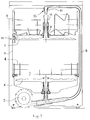
- the dishwashing machine basically comprises a wash tub 3 in which are housed at least a lower basket 4 and at least an upper basket 5 for supporting crockery.
- the baskets 4 and 5 are removable out of the wash tub 3 and are disposed above relevant spray arms 6 and 7, respectively, arranged to be fed with water, via a water supply conduit 8, by a circulating pump 9.
- the supply conduit 8 extends outside the wash tub 3 upwardly and terminates with a water distribution head 13; this latter protrudes into the wash tub passing through the top wall thereof and includes a central nozzle 10.
- the upper spray arm 7 is centrally provided with a substantially vertical collecting conduit through which it is rotatably supported by basket 5.
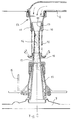
- the collecting conduit may comprise a diffuser 11 fixed to the spray arm 7 and forming a rotary hydraulic joint with a convergent tubular portion 12 which is mounted on the basket 5.
- the collecting conduit 11, 12 is axially aligned with the nozzle 10, from which it is spaced apart by an air gap, to receive from it a water jet illustrated at 14 in Figure 2.
- the upper basket 5 can preferably be selectively arranged at different vertical positions in the wash tub 3, so that the length of the air gap to be covered by the water jet 14 may vary accordingly (up to a maximum length of approx. 5 cm, for example).
- hydraulically operable means are provided to enclose the water jet 14 throughout the air gap between the collecting conduit 11, 12 and the nozzle 10, thereby substantially isolating the water jet from the interior of the wash tub 3, when the circulating pump 9 is in operation.
- such hydraulically operable means comprise a substantially annular aperture 16 which is formed on the water distribution head 13 so as to encircle the main nozzle 10.
- This latter in particular, is preferably made integral with the remaining portion of the water distribution head 13, to which it is fitted by means of at least two connection ridges 17.
- the latters preferably are thin and axially short, in order not to substantially affect the water jet (illustrated at 18 in Figure 2) issuing from the annular aperture 16, when the circulating pump 9 is in operation, with a substantially tubular configuration.
- the size of the annular aperture 16 may be easily calculated by those skilled in the art so as to obtain a laminar water jet 18 forming a water "wall" which is substantially uninterrupted throughout the angular and axial extent of the same water jet.
- the water jet 18 preferably impinges upon an annular baffle 19 projecting outwardly from the collecting conduit 11, 12.
- Such a baffle may for example be made integral with the tubular portion 12 and is arranged to divert the water jet 18 laterally (and/or upwardly) towards the crockery (not shown) disposed on the upper basket 5.
- the rotary spray arm 7 is supplied by the nozzle 10 with a water jet 14 via an air gap.
- the annular aperture 16 produces a laminar water jet 18 which completely encloses the water jet 14 throughout the air gap, thereby substantially isolating the water jet 14 from the interior of the wash tub 3.
- the laminar water jet 18 provides a tubular water wall surrounding the main water jet 14.
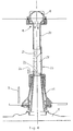
- the annular aperture 16 is omitted in the embodiment according to Figure 3, wherein the water distribution head 13 only comprises a nozzle 20 arranged in a per se known manner to produce a water jet 21 which has a substantially cylindrical and homogeneous configuration.
- the collecting conduit associated with the upper spray arm 7 preferably includes only the diffuser 11; in any case, the inlet mouth 22 of the collecting conduit has a smaller diameter than that of the water jet 21 in correspondence of the inlet mouth 22.
- the water jet 21 divides up into a central jet 23 which supplies the conduit 11 and then the spray arm 7, and a peripheral "isolating" annular jet 24 enclosing the inlet mouth 22.
- the edge of the inlet mouth 22 is preferably countersunk as shown in Figure 3.
- the peripheral water jet 24 preferably impinges upon an annular baffle 25 which, like the baffle 19 provided in the embodiment of Figure 2, protrudes outside from the collecting conduit 11 to divert the water jet 24 towards the crockery to be washed.
- the two water jets 23 and 24 are defined in dependence on the position of the inlet mouth 22 of the collecting conduit 11, it is necessary for a correct operation that the inlet mouth 22 be precisely aligned with the nozzle 20 when the basket 5 is inserted in the wash tub.
- the collecting conduit of the spray arm 7 preferably comprises a tapered tubular portion 26 mounted on the basket 5 and forming a rotary hydraulic joint with the diffuser 11.
- the tubular portion 26 extends from the inlet mouth 22 upwards with a peripheral projection 27 having an axial length which is longer than the maximum axial length of the air gap to be covered by the water jet 21 produced by the nozzle 20.
- a maximum axial length occurs when the upper basket 5 is arranged in the lowest of its selectively adjustable positions.
- the peripheral projection 27 is shaped with a cross-section substantially in the form of a circular segment, with an angular extension equal to or lower than 180°.
- the projection 27 is provided on the front side (right-hand side in Figure 4) of the tubular portion 26, that is, on the side facing the loading door (not shown) of the dishwashing machine.
- the projection 27 enables the basket 5 to be drawn out of the wash tub 3 in a usual fashion, while at least its inner upper portion is capable of stopping against the outer surface of the nozzle 20 (that to this purpose is preferably a cylindrical surface) when the basket 5 is inserted in its operative position.
- the projection 27 ensures correct axial alignment of the collecting conduit 11, 26 with the nozzle 20 and also partially surrounds the water jet 21 throughout the air gap it covers.
- the portion of water jet 21 which is not surrounded by the projection 27 is divided up, in correspondence of the inlet mouth 22 of the collecting conduit, into a central jet 23 (not shown in Figure 4 for the sake of simplicity) and a peripheral jet 24 which may be diverted towards the crockery being washed through baffle means (not shown for simplicity sake) similar to the baffle 25 shown in Figure 3. Therefore, the central water jet 23 (not shown in Figure 4) which supplies the spray arm 7 is isolated with respect to the interior of the wash tub, partially by the peripheral projection 27 and partially by the peripheral water jet 24.
- the aforementioned hydraulically operable means capable of enclosing the "supply" water jet throughout the air gap between the nozzle 20 and the collecting conduit of the spray arm 7 may have a completely mechanical structure, as shown in Figure 5.
- the collecting conduit associated with the spray arm 7 comprises a rotary hydraulic joint formed by a tubular portion 28 (mounted onto the basket 5) which is substantially cylindrical and provided with a tapered lower end 29 coupled with the diffuser 11.
- a coupling pipe 30 having suitable length and freely slidable telescopically upwards to couple with the nozzle 20 (preferably tapered) through a corresponding countersunk end portion 31.
- the coupling pipe 30 When the circulating pump 9 of the dishwashing machine is inoperative, the coupling pipe 30 is at least partially inserted by gravity in the tubular portion 28, as shown in continuous line in Figure 5. Under these conditions the upper end portion 31 of the collecting conduit 11, 28, 30 is spaced from the nozzle 20 by an air gap which allows the basket 5 to be drawn.
- the nozzle 20 When the circulating pump 9 is operated the nozzle 20 produces a water jet 21 which runs through the said air gap and is collected by the countersunk end portion 31 of the collecting conduit to supply the associated spray arm 7. Moreover, a proportion of the water jet 21 in the collecting conduit is diverted to flow upwardly along the gap between the tubular portion 28 and the coupling pipe 30.
- Such an upwardly extending water flow illustrated at 32 in Figure 5, impinges upon an annular baffle flange 33 formed on the outer surface of the coupling pipe 30.
- the hydraulic thrust exerted by the water flow 32 causes the coupling pipe 30 to telescopically slide upwards until its upper end portion 31 abuts against the nozzle 20 as shown in thick lines in Figure 5.
- this hydraulic reaction caused by the water flow 32 is effective even when the coupling pipe 30 is in its uppermost position, by virtue of the small axial length of the air gap and the substantially negligible friction occurring between the tubular members 28 and 30 when the coupling pipe is raised.
- the water jet 21 (or at least the proportion 23 thereof which supplies the spray arm 7) is surrounded by the coupling pipe 30, and is thereby isolated from the interior of the wash tub 3, throughout the air gap which separates the collecting conduit 11, 28, 30 from the nozzle 20 when the pump 9 is inoperative.
- the water jet 21 is prevented from drawing air, in correspondence of the air gap, into the spray arm 7, which would undesirably produce noise. Attention is also directed to the fact that even in this embodiment the reduced water flow 32 is advantageously diverted onto the crockery being washed thanks to the provision of the baffle 33.
Landscapes
- Washing And Drying Of Tableware (AREA)
Abstract
Description
- The present invention relates to a dishwashing machine provided with at least a rotary spray arm supported by a respective removable basket.
- As is known, dishwashing machines usually comprise a wash tub housing a lower removable basket and an upper removable basket for supporting the crockery, below the baskets being provided relevant rotatable spray arms which are supplied by a circulating pump. Preferably, the upper basket rotatably supports the respective spray arm and is selectively adjustable in height to contain crockery of different size; thus, it is necessary to provide detachable water connection means to supply the upper spray arm regardless of the vertical position of the associated basket.
- To this aim several arrangements have been provided, for instance as disclosed in EP-A-0 401 767, wherein the water circuit to supply the upper spray arm includes connection valve members which are selectively actuable according to the position of the upper basket. Such arrangements, however, involve undesirable complication in the structure of the dishwashing machine.
- Therefore, it is commonly preferable to use a water supply circuit of the kind disclosed for instance in GB-A-1 514 652, wherein the upper spray arm is fed with a water jet which issues from a nozzle disposed at the top of the wash tub, runs through an air gap and then is collected by a diffuser pipe extending vertically and connected with the spray arm.
- This arrangement is satisfactory in operation and simple and compact in construction, but on the other hand may be undesirably noisy. It is known, in fact, that in correspondence of the air gap the water jet tends to drag a given amount of air down into the diffuser pipe, this amount of air being "emulsified" in the pressurized water inside the upper spray arm, thereby producing substantial noise in correspondence of the washing jets issuing from the spray arm. The longer the air gap covered by the supply water jet, the length of the air gap being variable according to the vertical position of the upper basket, the more remarkable is the above phenomenon.
- It is the scope of the present invention to provide a dishwashing machine having at least a spray arm supported by a removable basket and provided with a particularly simple, reliable and noiseless water supply circuit.
- According to the invention, this scope is attained in a dishwashing machine with spray means supported by a removable basket embodying the features recited in the appended claims.
- The characteristics and advantages of the invention will become more apparent from the following description, given only by way of non-limiting example, with reference to the accompanying drawing, in which:
- Figure 1 diagrammatically shows a dishwashing machine according to the invention;
- Figure 2 is a sectioned elevational view of an enlarged detail of the dishwashing machine as in Figure 1, according to a preferred embodiment;
- Figure 3 is a sectioned elevational view of the enlarged detail as in Figure 2, according to another embodiment;
- Figure 4 is a partially sectioned view of the enlarged detail as in Figure 3, according to an alternative embodiment; and
- Figure 5 shows a sectional view of the enlarged detail as in Figure 2, according to a further embodiment.
- With reference to Figure 1, the dishwashing machine basically comprises a
wash tub 3 in which are housed at least alower basket 4 and at least anupper basket 5 for supporting crockery. In a known manner, thebaskets wash tub 3 and are disposed aboverelevant spray arms wash tub 3 upwardly and terminates with awater distribution head 13; this latter protrudes into the wash tub passing through the top wall thereof and includes acentral nozzle 10. Theupper spray arm 7 is centrally provided with a substantially vertical collecting conduit through which it is rotatably supported bybasket 5. As described for example in the afore-mentioned GB-A-1 514 652 and as shown in Figure 2, the collecting conduit may comprise adiffuser 11 fixed to thespray arm 7 and forming a rotary hydraulic joint with a convergenttubular portion 12 which is mounted on thebasket 5. Thus, when theupper basket 5 is placed in position into thewash tub 3 the collectingconduit nozzle 10, from which it is spaced apart by an air gap, to receive from it a water jet illustrated at 14 in Figure 2. - In a per se known manner, for instance by means of guide and
roller members 15, theupper basket 5 can preferably be selectively arranged at different vertical positions in thewash tub 3, so that the length of the air gap to be covered by thewater jet 14 may vary accordingly (up to a maximum length of approx. 5 cm, for example). - According to the invention, hydraulically operable means are provided to enclose the
water jet 14 throughout the air gap between the collectingconduit nozzle 10, thereby substantially isolating the water jet from the interior of thewash tub 3, when the circulating pump 9 is in operation. - In the embodiment shown in Figure 2, such hydraulically operable means comprise a substantially
annular aperture 16 which is formed on thewater distribution head 13 so as to encircle themain nozzle 10. This latter, in particular, is preferably made integral with the remaining portion of thewater distribution head 13, to which it is fitted by means of at least twoconnection ridges 17. The latters preferably are thin and axially short, in order not to substantially affect the water jet (illustrated at 18 in Figure 2) issuing from theannular aperture 16, when the circulating pump 9 is in operation, with a substantially tubular configuration. The size of theannular aperture 16 may be easily calculated by those skilled in the art so as to obtain alaminar water jet 18 forming a water "wall" which is substantially uninterrupted throughout the angular and axial extent of the same water jet. In addition, thewater jet 18 preferably impinges upon anannular baffle 19 projecting outwardly from thecollecting conduit tubular portion 12 and is arranged to divert thewater jet 18 laterally (and/or upwardly) towards the crockery (not shown) disposed on theupper basket 5. - The operation of the dishwashing machine should be apparent. When the
removable basket 5 is inserted into thewash tub 3 and the circulating pump 9 is operating, therotary spray arm 7 is supplied by thenozzle 10 with awater jet 14 via an air gap. Concurrently, theannular aperture 16 produces alaminar water jet 18 which completely encloses thewater jet 14 throughout the air gap, thereby substantially isolating thewater jet 14 from the interior of thewash tub 3. In other words, thelaminar water jet 18 provides a tubular water wall surrounding themain water jet 14. Hence, the velocity of thewater jet 14 is substantially prevented from causing ambient air to be drawn in thespray arm 7 in correspondence of the air gap, thespray arm 7 being thereby particularly noiseless in operation. - It was experimentally found that even a particularly thin
laminar water jet 18 is suitable to the purposes mentioned above; the water jet may temporarily "split" at localized areas to let air volumes pass which however are negligible as far as noise generation is concerned. This allows one to reduce to a minimum the proportion of water which must be subtracted out of the "supply"jet 14 to produce the "isolating"jet 18, which anyway is recovered, thanks to thebaffle 19, to spray the crockery. - The
annular aperture 16 is omitted in the embodiment according to Figure 3, wherein thewater distribution head 13 only comprises anozzle 20 arranged in a per se known manner to produce awater jet 21 which has a substantially cylindrical and homogeneous configuration. The collecting conduit associated with theupper spray arm 7 preferably includes only thediffuser 11; in any case, theinlet mouth 22 of the collecting conduit has a smaller diameter than that of thewater jet 21 in correspondence of theinlet mouth 22. As a consequence, only a central portion of thewater jet 21 enters thecollecting conduit 11; more particularly, in correspondence of theinlet mouth 22 thewater jet 21 divides up into acentral jet 23 which supplies theconduit 11 and then thespray arm 7, and a peripheral "isolating"annular jet 24 enclosing theinlet mouth 22. In order to promote such a division of the water jet, the edge of theinlet mouth 22 is preferably countersunk as shown in Figure 3. In addition, theperipheral water jet 24 preferably impinges upon anannular baffle 25 which, like thebaffle 19 provided in the embodiment of Figure 2, protrudes outside from thecollecting conduit 11 to divert thewater jet 24 towards the crockery to be washed. - The operation of the embodiment as in Figure 3 is similar to that described with reference to Figure 2, with the difference that the "supply"
water jet 23, consisting of the central portion of thewater jet 21 produced by thenozzle 20, is isolated from the interior of thewash tub 3 by theannular water jet 24, consisting of the peripheral layer of thewater jet 21 itself. - Obviously, since the two
water jets inlet mouth 22 of thecollecting conduit 11, it is necessary for a correct operation that theinlet mouth 22 be precisely aligned with thenozzle 20 when thebasket 5 is inserted in the wash tub. - This condition is more readily satisfied with the alternative embodiment shown in Figure 4, wherein, like in the embodiment shown in Figure 2, the collecting conduit of the
spray arm 7 preferably comprises a taperedtubular portion 26 mounted on thebasket 5 and forming a rotary hydraulic joint with thediffuser 11. Thetubular portion 26 extends from theinlet mouth 22 upwards with aperipheral projection 27 having an axial length which is longer than the maximum axial length of the air gap to be covered by thewater jet 21 produced by thenozzle 20. As is known, such a maximum axial length occurs when theupper basket 5 is arranged in the lowest of its selectively adjustable positions. Theperipheral projection 27 is shaped with a cross-section substantially in the form of a circular segment, with an angular extension equal to or lower than 180°. In addition, theprojection 27 is provided on the front side (right-hand side in Figure 4) of thetubular portion 26, that is, on the side facing the loading door (not shown) of the dishwashing machine. Hence, theprojection 27 enables thebasket 5 to be drawn out of thewash tub 3 in a usual fashion, while at least its inner upper portion is capable of stopping against the outer surface of the nozzle 20 (that to this purpose is preferably a cylindrical surface) when thebasket 5 is inserted in its operative position. Thus, theprojection 27 ensures correct axial alignment of the collectingconduit nozzle 20 and also partially surrounds thewater jet 21 throughout the air gap it covers. - In a similar way as described with reference to Figure 3, the portion of
water jet 21 which is not surrounded by theprojection 27 is divided up, in correspondence of theinlet mouth 22 of the collecting conduit, into a central jet 23 (not shown in Figure 4 for the sake of simplicity) and aperipheral jet 24 which may be diverted towards the crockery being washed through baffle means (not shown for simplicity sake) similar to thebaffle 25 shown in Figure 3. Therefore, the central water jet 23 (not shown in Figure 4) which supplies thespray arm 7 is isolated with respect to the interior of the wash tub, partially by theperipheral projection 27 and partially by theperipheral water jet 24. - As an alternative, the aforementioned hydraulically operable means capable of enclosing the "supply" water jet throughout the air gap between the
nozzle 20 and the collecting conduit of thespray arm 7 may have a completely mechanical structure, as shown in Figure 5. According to this embodiment of the invention, the collecting conduit associated with thespray arm 7 comprises a rotary hydraulic joint formed by a tubular portion 28 (mounted onto the basket 5) which is substantially cylindrical and provided with a taperedlower end 29 coupled with thediffuser 11. In thetubular portion 28 is loosely arranged acoupling pipe 30 having suitable length and freely slidable telescopically upwards to couple with the nozzle 20 (preferably tapered) through a correspondingcountersunk end portion 31. When the circulating pump 9 of the dishwashing machine is inoperative, thecoupling pipe 30 is at least partially inserted by gravity in thetubular portion 28, as shown in continuous line in Figure 5. Under these conditions theupper end portion 31 of thecollecting conduit nozzle 20 by an air gap which allows thebasket 5 to be drawn. - When the circulating pump 9 is operated the
nozzle 20 produces awater jet 21 which runs through the said air gap and is collected by thecountersunk end portion 31 of the collecting conduit to supply the associatedspray arm 7. Moreover, a proportion of thewater jet 21 in the collecting conduit is diverted to flow upwardly along the gap between thetubular portion 28 and thecoupling pipe 30. Such an upwardly extending water flow, illustrated at 32 in Figure 5, impinges upon anannular baffle flange 33 formed on the outer surface of thecoupling pipe 30. Hence, the hydraulic thrust exerted by thewater flow 32 causes thecoupling pipe 30 to telescopically slide upwards until itsupper end portion 31 abuts against thenozzle 20 as shown in thick lines in Figure 5. It should be noted that this hydraulic reaction caused by thewater flow 32 is effective even when thecoupling pipe 30 is in its uppermost position, by virtue of the small axial length of the air gap and the substantially negligible friction occurring between thetubular members - Therefore, when the circulating pump 9 is operating the water jet 21 (or at least the
proportion 23 thereof which supplies the spray arm 7) is surrounded by thecoupling pipe 30, and is thereby isolated from the interior of thewash tub 3, throughout the air gap which separates thecollecting conduit nozzle 20 when the pump 9 is inoperative. Thus, also in this embodiment thewater jet 21 is prevented from drawing air, in correspondence of the air gap, into thespray arm 7, which would undesirably produce noise. Attention is also directed to the fact that even in this embodiment the reducedwater flow 32 is advantageously diverted onto the crockery being washed thanks to the provision of thebaffle 33. - From the foregoing description the simple construction and operation of the dishwashing machine according to the invention should be apparent.
- Of course, the different embodiments described above by way of example may undergo a number of modifications without departing from the scopes of the invention.
Claims (9)
- Dishwashing machine comprising a wash tub in which it is housed at least a removable basket supporting a rotary spray arm arranged to be supplied with water by a circulating pump through a nozzle and a collecting conduit connected with the spray arm, said nozzle being capable of producing a water jet extending throughout an air gap which normally separates the inlet mouth of said collecting conduit from said nozzle, characterized in that hydraulically operable means (16,18; 22,24; 30) are provided capable of enclosing, throughout the said air gap, the water jet (14; 23; 21) which supplies said spray arm (7), so as to substantially isolating it from the interior of the wash tub (3), when said circulating pump (9) is in operation.
- Dishwashing machine according to claim 1, characterized in that said nozzle (10) is formed on a water distribution head (13) connected with said circulating pump (9) and provided with a substantially annular aperture (16) which encircles said nozzle and is arranged to produce a water wall (18) extending with a substantially uninterrupted tubular configuration, throughout said air gap, around the water jet (14) produced by said nozzle (10), said annular aperture (16) and said water wall (18) forming said hydraulically operable means.
- Dishwashing machine according to claim 2, characterized in that said water wall (18) impinges upon baffle means (19) projecting outwardly from said collecting conduit (11,12) and arranged to divert the water wall towards the crockery being washed.
- Dishwashing machine according to claim 1, characterized in that in correspondence of the inlet mouth (22) of said collecting conduit (11; 26) the water jet (21) produced by said nozzle (20) has a larger diameter than the inlet mouth, into which only a central portion (23) of the water jet (21) enters to supply said spray arm (7), a peripheral portion (24) of said water jet enclosing said inlet mouth (22) so as to form said hydraulically operable means therewith.
- Dishwashing machine according to claim 4, characterized in that said peripheral portion (24) of the water jet (21) impinges upon baffle means (25) projecting outwardly from said collecting conduit (11,26) and arranged to divert said peripheral portion towards the crockery being washed.
- Dishwashing machine according to claim 4, characterized in that said collecting conduit (11,26) comprises on its front side a peripheral projection (27) axially extending from said inlet mouth (22) towards said nozzle (20), against which it is arranged to stop, so as to partially surround the water jet (21) produced by said nozzle (20), when the removable basket (5) is positioned into the wash tub (3).
- Dishwashing machine according to claim 6, characterized in that said peripheral projection (27) is shaped with a cross-section substantially in the form of a circular segment, with an angular extension equal to or lower than 180°, said nozzle (20) having a substantially cylindrical outer surface capable of coupling at least partially with the inner surface of the peripheral projection (27).
- Dishwashing machine according to claim 1, characterized in that said hydraulically operable means comprise a coupling pipe (30) loosely arranged in said collecting conduit (28) and capable of receiving the water jet (21) produced by said nozzle (20) and sliding telescopically towards the nozzle, by hydraulic reaction, so as to couple therewith.
- Dishwashing machine according to claim 8, characterized in that baffle means (33) projecting outwardly from said coupling pipe (30) are provided to receive the hydraulic thrust exerted towards said nozzle (20) by a portion (32) of said water jet (21) flowing along the gap between the coupling pipe (30) and the collecting conduit (28), said baffle means (33) being arranged to divert said portion (32) of the water jet towards the crockery being washed.
Applications Claiming Priority (2)
| Application Number | Priority Date | Filing Date | Title |
|---|---|---|---|
| ITPN910023 | 1991-04-15 | ||
| ITPN910023A IT1250386B (en) | 1991-04-15 | 1991-04-15 | DISHWASHER WITH SPRAY REEL SUPPORTED BY A REMOVABLE BASKET. |
Publications (2)
| Publication Number | Publication Date |
|---|---|
| EP0509251A1 true EP0509251A1 (en) | 1992-10-21 |
| EP0509251B1 EP0509251B1 (en) | 1994-12-07 |
Family
ID=11394519
Family Applications (1)
| Application Number | Title | Priority Date | Filing Date |
|---|---|---|---|
| EP92104457A Expired - Lifetime EP0509251B1 (en) | 1991-04-15 | 1992-03-16 | Dishwashing machine with spray means supported by a removable basket |
Country Status (4)
| Country | Link |
|---|---|
| EP (1) | EP0509251B1 (en) |
| DE (1) | DE69200797T2 (en) |
| ES (1) | ES2067971T3 (en) |
| IT (1) | IT1250386B (en) |
Cited By (3)
| Publication number | Priority date | Publication date | Assignee | Title |
|---|---|---|---|---|
| DE4211559A1 (en) * | 1992-04-06 | 1993-10-07 | Miele & Cie | Dishwasher with at least one crockery rack - has arm supplied from cone below upper nozzle with free air section, surrounded by water curtain |
| EP2279687A1 (en) * | 2009-07-28 | 2011-02-02 | Electrolux Home Products Corporation N.V. | Spray arm arrangement for a dishwasher |
| CN114983309A (en) * | 2022-06-15 | 2022-09-02 | 杭州老板电器股份有限公司 | Spraying system and dish washing machine |
Citations (8)
| Publication number | Priority date | Publication date | Assignee | Title |
|---|---|---|---|---|
| DE1628600A1 (en) * | 1966-10-01 | 1970-08-20 | Philips Nv | Dishwasher |
| FR2062035A5 (en) * | 1969-10-08 | 1971-06-25 | Esswein & Cie | |
| DE2207373A1 (en) * | 1972-02-17 | 1973-08-23 | Miele & Cie | DISHWASHER WITH HEIGHT-ADJUSTABLE UPPER BASKET |
| GB1514652A (en) * | 1975-09-24 | 1978-06-21 | Zanussi A Spa Industrie | Dishwashers |
| DE3540238A1 (en) * | 1985-11-13 | 1987-05-14 | Blomberg Werke Kg | Dish-washing machine |
| DE8801390U1 (en) * | 1987-02-18 | 1988-05-11 | Industrie Zanussi S.P.A., Pordenone, Udine | Water circulation circuit for dishwasher |
| FR2620923A1 (en) * | 1987-09-25 | 1989-03-31 | Bosch Siemens Hausgeraete | MOUNTING OF A SPRAY ARM AND WATER SUPPLY DEVICE FOR A DISHWASHER |
| FR2651427A1 (en) * | 1989-09-05 | 1991-03-08 | Esswein Sa | Dishwasher with quiet water inlet |
-
1991
- 1991-04-15 IT ITPN910023A patent/IT1250386B/en active IP Right Grant
-
1992
- 1992-03-16 EP EP92104457A patent/EP0509251B1/en not_active Expired - Lifetime
- 1992-03-16 DE DE69200797T patent/DE69200797T2/en not_active Expired - Fee Related
- 1992-03-16 ES ES92104457T patent/ES2067971T3/en not_active Expired - Lifetime
Patent Citations (8)
| Publication number | Priority date | Publication date | Assignee | Title |
|---|---|---|---|---|
| DE1628600A1 (en) * | 1966-10-01 | 1970-08-20 | Philips Nv | Dishwasher |
| FR2062035A5 (en) * | 1969-10-08 | 1971-06-25 | Esswein & Cie | |
| DE2207373A1 (en) * | 1972-02-17 | 1973-08-23 | Miele & Cie | DISHWASHER WITH HEIGHT-ADJUSTABLE UPPER BASKET |
| GB1514652A (en) * | 1975-09-24 | 1978-06-21 | Zanussi A Spa Industrie | Dishwashers |
| DE3540238A1 (en) * | 1985-11-13 | 1987-05-14 | Blomberg Werke Kg | Dish-washing machine |
| DE8801390U1 (en) * | 1987-02-18 | 1988-05-11 | Industrie Zanussi S.P.A., Pordenone, Udine | Water circulation circuit for dishwasher |
| FR2620923A1 (en) * | 1987-09-25 | 1989-03-31 | Bosch Siemens Hausgeraete | MOUNTING OF A SPRAY ARM AND WATER SUPPLY DEVICE FOR A DISHWASHER |
| FR2651427A1 (en) * | 1989-09-05 | 1991-03-08 | Esswein Sa | Dishwasher with quiet water inlet |
Cited By (8)
| Publication number | Priority date | Publication date | Assignee | Title |
|---|---|---|---|---|
| DE4211559A1 (en) * | 1992-04-06 | 1993-10-07 | Miele & Cie | Dishwasher with at least one crockery rack - has arm supplied from cone below upper nozzle with free air section, surrounded by water curtain |
| EP2279687A1 (en) * | 2009-07-28 | 2011-02-02 | Electrolux Home Products Corporation N.V. | Spray arm arrangement for a dishwasher |
| WO2011012234A1 (en) * | 2009-07-28 | 2011-02-03 | Electrolux Home Products Corporation N.V. | Spray arm arrangement for a dishwasher |
| KR20120052351A (en) * | 2009-07-28 | 2012-05-23 | 일렉트로룩스 홈 프로덕츠 코오포레이션 엔.브이. | Spray arm arrangement for a dishwasher |
| AU2010278322B2 (en) * | 2009-07-28 | 2015-12-03 | Electrolux Home Products Corporation N.V. | Spray arm arrangement for a dishwasher |
| US9456730B2 (en) | 2009-07-28 | 2016-10-04 | Electrolux Home Products Corporation N.V. | Spray arm arrangement for a dishwasher |
| CN114983309A (en) * | 2022-06-15 | 2022-09-02 | 杭州老板电器股份有限公司 | Spraying system and dish washing machine |
| CN114983309B (en) * | 2022-06-15 | 2025-09-26 | 杭州老板电器股份有限公司 | Spray system and dishwasher |
Also Published As
| Publication number | Publication date |
|---|---|
| DE69200797T2 (en) | 1995-07-13 |
| IT1250386B (en) | 1995-04-07 |
| EP0509251B1 (en) | 1994-12-07 |
| ES2067971T3 (en) | 1995-04-01 |
| ITPN910023A1 (en) | 1992-10-15 |
| ITPN910023A0 (en) | 1991-04-15 |
| DE69200797D1 (en) | 1995-01-19 |
Similar Documents
| Publication | Publication Date | Title |
|---|---|---|
| US5546968A (en) | Supplementary washing device of a dish washer | |
| KR101704078B1 (en) | Spray arm assembly for a dishwasher | |
| US4509687A (en) | Multiple spray distribution system for a domestic dishwasher | |
| US4972861A (en) | Washing machine including improved apparatus for cleaning a recirculating filter thereof | |
| US3969137A (en) | Conduit for transmitting washing liquid to an upper spray arm in a dishwasher | |
| US3288156A (en) | Dishwasher with upwardly extensible distributor | |
| CA2428672A1 (en) | Bullet ended wash tube for dishwasher | |
| WO2002101796A3 (en) | Megasonic cleaner and dryer system | |
| CN105813533A (en) | Arrangement of dish washer for creating washing area with selective positions | |
| EP0509251B1 (en) | Dishwashing machine with spray means supported by a removable basket | |
| EP1169110B1 (en) | Improved method and system for collecting and handling dust in a papermachine environment | |
| GB2250912A (en) | Dishwasher | |
| EP0829221B1 (en) | Dishwashing machine with improved hydraulic circuit | |
| EP0772994B1 (en) | Dishwashing machine with improved hydraulic circuit | |
| US5433228A (en) | Self-cleaning bearing flange for dishwasher spray arm | |
| GB2210257A (en) | Crockery basket and spray unit assembly for a dishwashing machine | |
| US3385523A (en) | Dishwasher spraying assembly | |
| CN216777006U (en) | Cleaning machine | |
| CN107971287B (en) | Automatic cleaning equipment for thin-wall bushing | |
| US5381678A (en) | Fluid flow type dyeing apparatus | |
| IT1261064B (en) | DISHWASHER MACHINE PERFECTED | |
| JPH01246488A (en) | Recovering unit for shower water | |
| CN211660327U (en) | Blowing anti-blocking device of spray disk type humidifier | |
| CN217222638U (en) | Adjustable circuit board washing unit | |
| CN214612864U (en) | Spraying and upper edge baffle device of slow-pulling roller for pulling waste silk |
Legal Events
| Date | Code | Title | Description |
|---|---|---|---|
| PUAI | Public reference made under article 153(3) epc to a published international application that has entered the european phase |
Free format text: ORIGINAL CODE: 0009012 |
|
| AK | Designated contracting states |
Kind code of ref document: A1 Designated state(s): DE ES FR GB IT |
|
| 17P | Request for examination filed |
Effective date: 19930211 |
|
| 17Q | First examination report despatched |
Effective date: 19940323 |
|
| ITF | It: translation for a ep patent filed | ||
| GRAA | (expected) grant |
Free format text: ORIGINAL CODE: 0009210 |
|
| AK | Designated contracting states |
Kind code of ref document: B1 Designated state(s): DE ES FR GB IT |
|
| REF | Corresponds to: |
Ref document number: 69200797 Country of ref document: DE Date of ref document: 19950119 |
|
| ET | Fr: translation filed | ||
| PLBE | No opposition filed within time limit |
Free format text: ORIGINAL CODE: 0009261 |
|
| STAA | Information on the status of an ep patent application or granted ep patent |
Free format text: STATUS: NO OPPOSITION FILED WITHIN TIME LIMIT |
|
| 26N | No opposition filed | ||
| REG | Reference to a national code |
Ref country code: ES Ref legal event code: PC2A Owner name: ELECTROLUX ZANUSSI ELETTRODOMESTICI, S.P.A. |
|
| REG | Reference to a national code |
Ref country code: ES Ref legal event code: PC2A |
|
| PGFP | Annual fee paid to national office [announced via postgrant information from national office to epo] |
Ref country code: FR Payment date: 20000214 Year of fee payment: 9 |
|
| PGFP | Annual fee paid to national office [announced via postgrant information from national office to epo] |
Ref country code: GB Payment date: 20000222 Year of fee payment: 9 |
|
| PGFP | Annual fee paid to national office [announced via postgrant information from national office to epo] |
Ref country code: DE Payment date: 20000228 Year of fee payment: 9 |
|
| PGFP | Annual fee paid to national office [announced via postgrant information from national office to epo] |
Ref country code: ES Payment date: 20000307 Year of fee payment: 9 |
|
| PG25 | Lapsed in a contracting state [announced via postgrant information from national office to epo] |
Ref country code: GB Free format text: LAPSE BECAUSE OF NON-PAYMENT OF DUE FEES Effective date: 20010316 |
|
| PG25 | Lapsed in a contracting state [announced via postgrant information from national office to epo] |
Ref country code: ES Free format text: LAPSE BECAUSE OF NON-PAYMENT OF DUE FEES Effective date: 20010317 |
|
| GBPC | Gb: european patent ceased through non-payment of renewal fee |
Effective date: 20010316 |
|
| PG25 | Lapsed in a contracting state [announced via postgrant information from national office to epo] |
Ref country code: FR Free format text: LAPSE BECAUSE OF NON-PAYMENT OF DUE FEES Effective date: 20011130 |
|
| REG | Reference to a national code |
Ref country code: FR Ref legal event code: ST |
|
| PG25 | Lapsed in a contracting state [announced via postgrant information from national office to epo] |
Ref country code: DE Free format text: LAPSE BECAUSE OF NON-PAYMENT OF DUE FEES Effective date: 20020101 |
|
| REG | Reference to a national code |
Ref country code: ES Ref legal event code: FD2A Effective date: 20030203 |
|
| PG25 | Lapsed in a contracting state [announced via postgrant information from national office to epo] |
Ref country code: IT Free format text: LAPSE BECAUSE OF NON-PAYMENT OF DUE FEES Effective date: 20050316 |