EP0509014B1 - Selbsthaltender strumpf - Google Patents
Selbsthaltender strumpf Download PDFInfo
- Publication number
- EP0509014B1 EP0509014B1 EP91901876A EP91901876A EP0509014B1 EP 0509014 B1 EP0509014 B1 EP 0509014B1 EP 91901876 A EP91901876 A EP 91901876A EP 91901876 A EP91901876 A EP 91901876A EP 0509014 B1 EP0509014 B1 EP 0509014B1
- Authority
- EP
- European Patent Office
- Prior art keywords
- stocking
- sleeve
- turntable
- support
- welt
- Prior art date
- Legal status (The legal status is an assumption and is not a legal conclusion. Google has not performed a legal analysis and makes no representation as to the accuracy of the status listed.)
- Expired - Lifetime
Links
- 229920001296 polysiloxane Polymers 0.000 claims abstract description 32
- 239000000463 material Substances 0.000 claims abstract description 21
- 238000004519 manufacturing process Methods 0.000 claims abstract description 4
- 230000007246 mechanism Effects 0.000 claims description 5
- 238000000034 method Methods 0.000 abstract description 4
- XUIMIQQOPSSXEZ-UHFFFAOYSA-N Silicon Chemical compound [Si] XUIMIQQOPSSXEZ-UHFFFAOYSA-N 0.000 description 5
- 238000001125 extrusion Methods 0.000 description 5
- 229910052710 silicon Inorganic materials 0.000 description 5
- 239000010703 silicon Substances 0.000 description 5
- 230000015572 biosynthetic process Effects 0.000 description 3
- 238000005755 formation reaction Methods 0.000 description 3
- 238000001035 drying Methods 0.000 description 2
- 229920001971 elastomer Polymers 0.000 description 2
- 239000004744 fabric Substances 0.000 description 2
- 229920003051 synthetic elastomer Polymers 0.000 description 2
- 239000000806 elastomer Substances 0.000 description 1
- 230000009969 flowable effect Effects 0.000 description 1
- 238000002347 injection Methods 0.000 description 1
- 239000007924 injection Substances 0.000 description 1
- 239000007788 liquid Substances 0.000 description 1
- 235000011837 pasties Nutrition 0.000 description 1
- 239000002210 silicon-based material Substances 0.000 description 1
Images

Classifications
-
- A—HUMAN NECESSITIES
- A41—WEARING APPAREL
- A41B—SHIRTS; UNDERWEAR; BABY LINEN; HANDKERCHIEFS
- A41B11/00—Hosiery; Panti-hose
- A41B11/02—Reinforcements
- A41B11/04—Reinforcements of the stocking top
-
- A—HUMAN NECESSITIES
- A41—WEARING APPAREL
- A41B—SHIRTS; UNDERWEAR; BABY LINEN; HANDKERCHIEFS
- A41B11/00—Hosiery; Panti-hose
- A41B11/12—Means at the upper end to keep the stockings up
- A41B11/126—Means at the upper end to keep the stockings up having friction increasing means
-
- B—PERFORMING OPERATIONS; TRANSPORTING
- B65—CONVEYING; PACKING; STORING; HANDLING THIN OR FILAMENTARY MATERIAL
- B65D—CONTAINERS FOR STORAGE OR TRANSPORT OF ARTICLES OR MATERIALS, e.g. BAGS, BARRELS, BOTTLES, BOXES, CANS, CARTONS, CRATES, DRUMS, JARS, TANKS, HOPPERS, FORWARDING CONTAINERS; ACCESSORIES, CLOSURES, OR FITTINGS THEREFOR; PACKAGING ELEMENTS; PACKAGES
- B65D33/00—Details of, or accessories for, sacks or bags
- B65D33/16—End- or aperture-closing arrangements or devices
- B65D33/25—Riveting; Dovetailing; Screwing; using press buttons or slide fasteners
- B65D33/2508—Riveting; Dovetailing; Screwing; using press buttons or slide fasteners using slide fasteners with interlocking members having a substantially uniform section throughout the length of the fastener; Sliders therefor
- B65D33/2516—Riveting; Dovetailing; Screwing; using press buttons or slide fasteners using slide fasteners with interlocking members having a substantially uniform section throughout the length of the fastener; Sliders therefor comprising tamper-indicating means, e.g. located within the fastener
- B65D33/2525—Riveting; Dovetailing; Screwing; using press buttons or slide fasteners using slide fasteners with interlocking members having a substantially uniform section throughout the length of the fastener; Sliders therefor comprising tamper-indicating means, e.g. located within the fastener located between the fastener and the product compartment
-
- D—TEXTILES; PAPER
- D06—TREATMENT OF TEXTILES OR THE LIKE; LAUNDERING; FLEXIBLE MATERIALS NOT OTHERWISE PROVIDED FOR
- D06B—TREATING TEXTILE MATERIALS USING LIQUIDS, GASES OR VAPOURS
- D06B3/00—Passing of textile materials through liquids, gases or vapours to effect treatment, e.g. washing, dyeing, bleaching, sizing, impregnating
- D06B3/10—Passing of textile materials through liquids, gases or vapours to effect treatment, e.g. washing, dyeing, bleaching, sizing, impregnating of fabrics
Definitions
- the present invention relates to self supporting stockings.
- a stocking In wear, a stocking is usually held in position on a wearer's leg by means of either suspenders or an elastic lace or braid ring, stitched to the welt of the stocking.
- an elastic lace or braid ring In some types of elastic lace or braid ring a horizontal silicone stripe or stripes are attached within the ring in order to provide the necessary adhesion between the skin of the wearer's leg and the top of the stocking, thus keeping the stocking in place.
- such lace or braid rings were made up from a continuous strip which incorporates normally two silicone stripes.
- the required length of lace or braid is cut from the continuous strip and the two ends are then seamed together to form a ring.
- the ring is then attached to the top of a stocking by a further seam to form a welt.
- GB-A-1,171,063 representing the most relevant prior art, describes a method of manufacturing a self-supporting stocking in which at least one of the facers of the fabric of the stocking is coated with a synthetic elastomer material in the pasty or liquid state, causing the material to diffuse into the fabric and allowing the synthetic elastomer material to set.
- the elastomer material is formed in one or more support bands on the stocking a short distance from the top edge of the stocking.
- the present invention seeks to provide an improved method and apparatus for producing self supporting stockings.
- the present invention provides a method of manufacturing a self supporting stocking comprising supporting said stocking; applying silicone material onto the surface of the welt ring of the stocking in such a manner as to form a stripe over at least a part of the circumference thereof; and subsequently curing said silicone material; characterised in that said stocking is supported with the welt ring interior facing radially outwardly of the stocking; and wherein said stocking is rotated about its longitudinal axis whilst applying said silicone material on to the outwardly facing surface of the welt ring.
- the present invention also provides an apparatus for producing a self supporting stocking comprising means for supporting said stocking (1) and means (30,31) for applying silicone material onto the surface of the welt ring (2) of the stocking in such a manner as to form a stripe (5) over at least a part of the circumference thereof and means for subsequently curing said silicone material characterised in that the support means support the stocking with the welt ring interior facing radially outwardly of the stocking; in that means are provided for rotating said supported stocking about its longitudinal axis at an application station; in that the silicone material is applied by means (30,31) onto the outwardly facing surface of the welt ring during rotation; and in that conveyor means are conveying said support means through said application station and curing means.
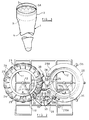
- this illustrates a known self-supporting stocking, designated generally 1, having a welt ring 2 seamed at 3 to of a stocking portion 4 and having a silicone stripe 5 on its internal surface.
- An alternative or additional possibility of providing a sinuous stripe is indicated in broken lines at 5A and various other plural stripe arrangements are possible.
- the invention is particularly concerned with a method and apparatus for applying the silicone stripe or stripes in a simple and convenient manner.
- FIG. 2 A preferred form of the apparatus of the invention is illustrated in Figure 2 and will be seen to comprise a main frame 10 on which are mounted a pair of turntables 11 and 12 arranged for indexed angular movement. Indexing is effected by respective indexing arms 13, 14 interconnected by a pair of links 15, 16 reciprocally driven from a crank represented diagrammatically at 17.
- the drive input to the crank is shown as a belt 18 engaged around a main drive pulley 19 itself driven by a further belt or the like 20A from a drive motor 20.
- the crank operates in conjunction with a pair of escapements, which, in the illustrated arrangements are in the form of pawls 21, 22 pivoted respectively on the ends of the arms 13, 14 and co-operating with ratchet formations (not shown) on the turntable.
- the pawls and ratchets are arranged so that angular reciprocation of the arms 13, 14 cause the turntables to be driven uni-directionally and consecutively in opposite directions.
- the turntable 12 indexes in a clockwise direction and the turntable 11 in an anti-clockwise direction, as indicated by the respective arrows A, B.
- Each turntable has a central support ring 23, which may conveniently carry the ratchet formations with which the associated one of the indexing arms 13, 14 cooperates.
- Each ring supports a series of juxtaposed radial arms 24, each of which carries a respective stocking support device 25.
- the upper surfaces of the arms carry a cover plate 26 mounted on a ring 26A secured to the arms ( Figure 5).
- Upper portions of the devices 25 project upwardly from the plate 26, and can be seen more clearly from the right hand side of Figure 2 in which the arms underlie the plate and are hidden thereby.
- the plate 26 supports upstanding flanges 27 which are located respectively after every second one of the support devices 25 so that the devices 25 are effectively separated into pairs, for the purpose to be described.
- a curing and drying oven 28 which will be described in detail hereinafter.
- Upper and lower silicone extrusion devices 30, 31 lie between the turntables, in operative relation to adjacent ones of the support devices 25.
- a drive belt 32 encircles the support devices 25 in driving engagement over the majority of the circumference of each turntable and is driven and directed by a pulley system indicated generally at 33, the drive input for which is taken from the main pulley 19.
- the oven 28 and part of the plate 26 are illustrated in more detail in Figure 3, the oven being seen rotated slightly from its normal position in Figure 2, for ease of illustration.
- the oven 28 encloses the whole of the area above the plate 26 except for a portion of sufficient length to expose two pairs of support devices 25.
- the upstanding flanges 27 are formed by providing generally U-shaped elements, of which the juxtaposed arms 27A are joined together by rivets 34, or other suitable means.
- Sandwiched between the arms is a rubber wiper element 35 which projects slightly outwardly of the sides and upper edges of the arms and is such as to form a seal against the inner side and upper surfaces of the relatively narrow entry and exit portions 28A of the oven.
- Steam inlet pipes 36 are provided at intervals around the oven for introduction of steam therein. The lower edges of the oven sides seal by way of radially inner and outer brushes 37, 38 against the cover plate 26.
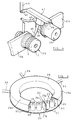
- Figure 4 illustrates in more detail one of the silicon extrusion devices 30.
- Two arms 24 are illustrated, respectively from each of the turntables 11, 12 and each carries a support device 25, one of which carries a stocking 1 contained largely within the support device, but with the stocking welt ring 2 turned inside out over the outer surface of the device 25.
- the particular extrusion device 30 illustrated is intended to provide a single stripe of silicon on the stocking welt and is provided with a single nozzle 40 mounted on a support arm 41 which, by way of a cranked connection 42 to a power arm 43 can be pivoted about a shaft 44 between positions in which the nozzle 40 (in full lines) is directed towards the illustrated supported stocking and (in broken lines) in which the nozzle is directed towards the other stocking support device 25 upon which a further stocking (not shown) would similarly be carried.
- the nozzle is connected via a suitable conduit 45 to a pressurised source of flowable silicon material.
- FIG. 5 illustrates, in greater detail, one of the stocking support devices 25 and its relationship with various other parts of the apparatus.
- the support device can be seen to comprise a main cylindrical body portion 50 secured by bolts 51 to the associated radial arm 24 which is itself rigidly secured by bolts 52 to the ring 23.
- the free inner end of the skirt 58 is sealed relative to the plate 26 and fixed cylinder 50 by way of seal 59 carried by the skirt and providing a rotary sliding seal between the skirt and components 26 and 50, during operation of the stocking support device 25.
- a further cylindrical portion of greater diameter than the remainder Surrounding and secured to the lower end portion of the inner sleeve 54 is a further cylindrical portion of greater diameter than the remainder which forms a driving drum 60 having a pair of axially spaced driving grooves 60A, 60B for engagement by the drive belt 32 at opposite sides thereof.
- Other parts of the pulley system 33, including the main drive pulley 19 can also be seen in Figure 5 in their operative relationship relative to the stocking support device 25.
- a closure plate 61 Secured to the open lower end of the drive drum 60 is a closure plate 61 which forms a blind end to both the drum and the inner sleeve 54.
- the lower end portion of the inner sleeve 54 is provided with longitudinal rows of radial holes 62 providing communication between the respective interiors of the sleeve 54 and drum 60, the latter communicating via axial holes 63 in the plate 61 with a cap 64 secured to the underside of the plate 61 and having an opening 65 which is normally closed by a ball valve 66 disposed within a guide sleeve 61A and located in its position indicated in broken lines.
- a vacuum duct 67 extends beneath the stocking support device 25 and, as can be seen from Figure 2, two such ducts are provided, one for each turntable, each duct extending between a pair of stocking support devices 25.
- Each duct has a pair of spaced apertures 68, the spacing between which corresponds to the spacing between a pair of support devices 25.
- a ring 69 is secured in position around each aperture 68 and carries an annular brush seal 70, arranged to engage the underside of the cap 64, when the support device 25 is in the position illustrated.
- a leaf spring 71 is supported on the upper surface of the duct 67, or at any other convenient location, and extends generally diametrically across the opening 65 in the cap 64. With the support device 25 in its illustrated position, the spring 71 acts to urge the ball 66 inwardly to its position shown in full lines, against the action of a return spring 66A.
- Movement of the arm 14 causes the right hand turntable 12 to be indexed through an angular distance, typically about 40°, equal to that occupied by a pair of arms 24, so that the support devices 25 at positions Y, Z both move away from their illustrated positions into the adjacent narrow part 28A of the oven 28, while the adjacent pair of devices 25 at positions W, X move to occupy the positions Y, Z which constitute an application station, and in doing so become engaged with the belt 32 (visible only in relation to the turntable 11), which causes the sleeve 54 and attached skirt 58 of each of these two devices to rotate.
- the turntable 11 remains stationary, the pawl 21 of the arm 13 moving over the cooperating ratchet formation to a position of readiness for indexing the turntable 12 at the next stroke of the indexing mechanism.
- the silicone extrusion devices 30, 31 are now activated, if necessary preceded by an angular movement of the support arms 41 to bring the nozzles 40 into operative position adjacent the support devices at positions Y, Z, and a ring of silicone is deposited upon the welt ring 2 of a stocking 1 supported on each of these devices.
- a further actuation of the indexing mechanism takes place to bring stockings loaded on the support devices at positions W, X at the loading/unloading station of the turntable 11 into the next positions adjacent to the silicone extrusion devices 30, 31, accompanied by concomitant movement of any previously treated stockings, on the support devices at positions Y, Z of this turntable into the adjacent oven portion 28A.
- the newly loaded stockings may then have silicone rings deposited thereon, as described previously.
- the turntable 12 remains stationary, the pawl 22 of the indexing arm 14 performing a ratcheting return movement as already described in relation to the arm 13.
- a subsequent further indexing movement now moves the turntable 12 through a further 40°, taking the previously treated stockings on this turntable into the adjacent narrow part 28A of the oven 28.
- Steam is injected continuously via the inlets 36 into the oven 28, but the flanges 27 entering the narrow portion 28A and engaging the internal surfaces thereof effectively form a trap which prevents the steam leaving the oven through the open ends thereof.
- the flanges Once the flanges pass into the wider oven portion, the flanges become clear of the oven walls to permit the required circulation of steam around the treated stockings for the purpose of curing the silicon. It would be possible to interrupt injection of steam and supply warm air into the oven to dry the stockings after curing has taken place; alternatively, the oven may be further divided internally to form a drying chamber downstream of the curing chamber.
- the apparatus of the invention may differ in many respects from that described above.
- the rotary turntables may be replaced by a linear conveyor which guides a plurality of stocking support members through loading, silicon application and curing stations during the performance of the method of the invention.
- operation of the conveyor and silicon applying means is preferably effected in timed relationship without intervention of an operative other than to load and unload stockings.
- twin turntable arrangement has been described with the turntables operating in conjunction with each other, it would be possible for them to operate independently so that one may continue operation while the other is being repaired or serviced, for example.
Landscapes
- Engineering & Computer Science (AREA)
- Textile Engineering (AREA)
- Mechanical Engineering (AREA)
- Socks And Pantyhose (AREA)
- Treatment Of Fiber Materials (AREA)
- Medical Preparation Storing Or Oral Administration Devices (AREA)
- Nitrogen And Oxygen Or Sulfur-Condensed Heterocyclic Ring Systems (AREA)
- Pharmaceuticals Containing Other Organic And Inorganic Compounds (AREA)
Claims (16)
- Eine Vorgangsweise zur Herstellung eines selbsthaltenden Strumpfs (1), bestehend aus einer Aufziehvorrichtung für besagten Strumpf;
Auftragen von Siliziummaterial auf die Oberfläche des Bundrings (2) des Strumpfs auf solche Art und Weise, daß ein Streifen (5) Über wenigstens einen Teil eines Umfangs aufgetragen wird;
mit nachträglicher Härtung besagten Siliziummaterials;
gekennzeichnet dadurch, daß besagter Strumpf so aufgezogen wird, daß die Innenseite des Bundrings radial nach außen gewendet ist;
und wobei besagter Strumpf um seine Längsachse gedreht wird, während besagtes Siliziummaterial auf die nach außen gewendete Seite des Bundrings aufgetragen wird. - Gerät zur Herstellung besagten selbsthaltenden Strumpfs, bestehend aus einer Einrichtung zum Aufziehen besagter Strümpfe (1) sowie einer Einrichtung (30, 31) zum Auftragen von Siliziummaterial auf die Oberfläche des Bundrings (2) des Strumpfs auf solche Weise, daß ein Streifen (5) über wenigstens einen Teil dessen Umfangs gebildet wird sowie eine Einrichtung zum nachträglichen Härten besagten Siliziummaterials; wobei
die Aufziehvorrichtung (25) den Strumpf (1) mit der Innenseite des Bundrings radial nach außen gewendet aufzieht;
wobei eine Vorrichtung (32) das Drehen besagten aufgespannten Strumpfs um seine Längsachse an einer Auftragestation vorsieht;
wo das Siliziummaterial mit Hilfe von Einrichtungen (30, 31) auf die nach außen gewendete Innenseite des Bundrings aufgetragen wird, während der Strumpf gedreht wird;
wobei Fördereinrichtungen (11, 12) vorgesehen sind, die dem Transport besagter Aufziehvorrichtungen durch besagte Auftragestation und Härtungseinrichtung dienen. - Gerät nach Anspruch 2, wobei die Fördereinrichtungen (11, 12) vortaktbare Drehscheiben sind, auf denen die Strumpfaufziehvorrichtungen (25) nacheinander zur Auftragestation zum Auftragen des Siliziummaterials auf die auf den Aufziehvorrichtungen aufgezogenen Strümpfe und von dort in die Härtungseinrichtung (28) bewegt werden.
- Gerät nach Anspruch 2 oder Anspruch 3, wobei jede Aufziehvorrichtung (25) ein drehbares Stützteil (55) vorsieht, auf dem ein Strumpfbundring (2) mit Innenseite nach außen gewendet gehalten wird, wobei besagtes Teil (55) wenigstens in besagter Auftragestation gedreht wird, um einen Streifen Siliziummaterial durch besagte Auftrageeinrichtung (30, 31), die relativ starr ist, auf den Umfang besagten Bundes aufzutragen.
- Gerät nach Anspruch 4, wobei das Stützteil (55) aller Aufziehvorrichtungen (25) zum gleichzeitigen Drehen in ein endloses Antriebsteil (32) eingreift, während jede Vorrichtung an der Strumpflade-/-abnahmestation vom Triebteil getrennt wird.
- Gerät nach Anspruch 5, wobei das Triebteil (32) und die Fördereinrichtung (11, 12) von einem Motor (20) angetrieben werden.
- Gerät nach einem der Ansprüche 3 bis 6, wobei der Vorschub der Drehscheiben (11, 12) effektiv durch einen rechtwinklig hin und her beweglichen Vorschubarm (13, 14) erfolgt, der durch einen Klinken- und Ratschenmechanismus mit der Drehscheibe verkuppelt ist, so daß die Drehscheibe nur in eine Richtung vorgeschoben wird.
- Gerät nach einem der Ansprüche 3 bis 7, wobei die Drehscheibe (11, 12) mittels eines rechtwinkligen Abstands gleich dem, der von den benachbarten zwei Aufziehvorrichtungen (25) eingenommen wird, vorgeschoben wird, so daß der Vorschub in Paaren erfolgt. Dabei weist die Auftragestation zwei Auftrageeinrichtungen (40) auf, wo Siliziummaterial gleichzeitig auf ein Paar Strümpfe (1) aufgetragen wird, die auf zwei nebeneinander liegenden Aufziehvorrichtungen getragen werden.
- Gerät nach einem der Ansprüche 2 bis 8, wobei besagte Härtungseinrichtung ein Gehäuse (28) vorsieht, das um einen Teil des Umfangs der Drehscheiben (11, 12) verläuft und zur Aufnahme von Dampf und/oder Heißwasser ausgeführt ist, während die Härtungseinrichtung relativ schmale Einlauf- und Auslaufteile aufweist, die als Fallen wirken und die das Ausströmen von Dampf/Heißluft an die Außenseite größtenteils verhindern.
- Gerät nach Anspruch 9, wobei die Aufziehvorrichtungen auf eine runde Platte (26) aufgezogen sind, die Bestandteil der Drehscheibe (11, 12) ist. Die Platte hat aufrechte Flansche (27, 27A), mit denen die Geräte gegeneinander oder in Gruppen unterteilt werden, wobei jeder Flansch eine flexible Wischdichtung (35) über einen Teil seiner Peripherie vorsieht, die die Innenseiten besagter schmaler Ofeneinlauf- und Auslaufteile berührt, um besagte Fallen zu bilden.
- Gerät nach Anspruch 10, wobei die runde Platte (26) eine Anzahl von U-förmigen Teilen aufweist, die an ihren Armen zum Bilden der Flansche (27, 27A) miteinander verbunden sind, während die Wischdichtung (35) ein flexibles Teil zwischen nebeneinander liegenden Armen darstellt, das aus der Peripherie seines zugehörigen Flansches vorsteht.
- Gerät nach einem der Ansprüche 4 bis 11, wobei das drehbare Stützteil (55) der Aufziehvorrichtung (25) eine zylindrische Hülse (54) vorsieht, die in einer starren Stütze (50) drehbar befestigt ist, wobei die Hülse zum automatischen Anschluß an ein Saugdruckrohr (67) bei besagter Ladestation ausgeführt ist, um in der Hülse (54) negativen Luftdruck zu erzeugen, wodurch ein in ein offenes Ende der Hülse eingeführter Strumpf (1) teilweise ins Innere der Hülse gesaugt wird, wobei der Bundring (2) außen bleibt, um über eine externe Fläche der Aufziehvorrichtung (55) in Bereitschaft des Auftragens von Siliziummaterial aufgezogen zu werden.
- Gerät nach Anspruch 12, wobei das Saugdruckrohr (67) eine Lieferöffnung (68) vorsieht, in das die Hülse (54) der Aufziehvorrichtung (25) an der Ladestation einrastet. Die Hülse hat eine Einlauföffnung, die normalerweise durch ein Ventilteil (66) versperrt ist, das durch Kontakt mit der relativ starren Einrichtung (71) an besagter Ladestation verdrängt wird, um die Innenseite der Hülse mit besagter Lieferöffnung (68) in Kontakt zu bringen, um einen in das offene Ende der Hülse eingeführten Strumpf abseits vom Saugdruckrohr anzusaugen.
- Gerät nach Anspruch 13, wobei der Verbindungsweg zwischen dem Innenraum der Hülse und der Rohrlieferöffnung (68) teilweise entlang der Außenseite der Hülse (54) und über die allgemein radiale Öffnungseinrichtung (62) in der Hülsenwand verläuft.
- Gerät nach Anspruch 13 oder 14, wobei das Ventilteil eine unter Federdruck stehende Kugel (66) ist, die von einer Blattfeder (71) verdrängt wird, die allgemein diametral über der Hülseneinlauföffnung angeordnet ist.
- Gerät nach einem der Ansprüche 2 bis 15, wobei die Fördereinrichtung (11, 12) zwei gegeneinander verschiebbare Drehscheiben sind, die abwechselnd vorgeschoben werden, um die jeweils darauf befindliche Aufziehvorrichtung (25) nacheinander in besagte Auftragestation zu befördern, wobei der Vorschub mittels rechtwinklig beweglicher mechanisch verbundener Vorschubarme (13, 14) erfolgt, die jeweils mit den Drehscheiben (11, 12) verbunden sind und über Klinken und Ratschenmechanismen (21, 22) so aktiviert werden, daß die Bewegung der Arme in eine Richtung zum Bewegen einer Drehscheibe in eine Richtung und Bewegung der Arme in entgegengesetzte Richtung zum Bewegen der anderen Drehscheibe in entgegengesetzte Richtung führt.
Applications Claiming Priority (3)
| Application Number | Priority Date | Filing Date | Title |
|---|---|---|---|
| GB909000212A GB9000212D0 (en) | 1990-01-05 | 1990-01-05 | Self supporting stockings |
| GB9000212 | 1990-01-05 | ||
| PCT/GB1991/000006 WO1991009543A1 (en) | 1990-01-05 | 1991-01-04 | Self supporting stockings |
Publications (2)
| Publication Number | Publication Date |
|---|---|
| EP0509014A1 EP0509014A1 (de) | 1992-10-21 |
| EP0509014B1 true EP0509014B1 (de) | 1995-09-20 |
Family
ID=10668865
Family Applications (1)
| Application Number | Title | Priority Date | Filing Date |
|---|---|---|---|
| EP91901876A Expired - Lifetime EP0509014B1 (de) | 1990-01-05 | 1991-01-04 | Selbsthaltender strumpf |
Country Status (7)
| Country | Link |
|---|---|
| EP (1) | EP0509014B1 (de) |
| JP (1) | JPH05502699A (de) |
| AT (1) | ATE128008T1 (de) |
| DE (1) | DE69113248T2 (de) |
| ES (1) | ES2082964T3 (de) |
| GB (2) | GB9000212D0 (de) |
| WO (1) | WO1991009543A1 (de) |
Families Citing this family (11)
| Publication number | Priority date | Publication date | Assignee | Title |
|---|---|---|---|---|
| GB2305870A (en) * | 1995-10-04 | 1997-04-23 | Finden Coatings Ltd | Coating to assist fabric grip |
| GB9618090D0 (en) * | 1996-08-29 | 1996-10-09 | Finden Coatings Ltd | Narrow fabrics |
| EP1608505B1 (de) * | 2003-03-18 | 2012-07-18 | Stretchline Intellectual Properties Limited | Klebstoff beschichtetes gewebematerial |
| WO2006011168A1 (en) * | 2004-07-30 | 2006-02-02 | Gruppo Decortex S.R.L. | Item having silicone inserts printed by serigraphy and process for manufacturing said item |
| FR2904194B1 (fr) * | 2006-07-28 | 2008-10-10 | Cheynet & Fils Sa | Dispositif de maintien a base de silicone de produit textile a porter |
| FR2940168B1 (fr) * | 2008-12-19 | 2012-10-19 | Cheynet & Fils | Procede d'assemblage d'une bande support avec une matiere adhesive et installation de mise en oeuvre du procede |
| FR2941646B1 (fr) * | 2009-01-30 | 2011-02-25 | Cheynet & Fils | Procede de depose d'au moins une bande de rubans silicones sur l'envers d'un support textile auto fixant |
| GB2481867A (en) * | 2010-07-07 | 2012-01-11 | Stretchline Intellectual Properties Ltd | Fabric with elastomeric bonded hem |
| GB2481830A (en) * | 2010-07-07 | 2012-01-11 | Stretchline Intellectual Properties Ltd | Applying adhesive to a fabric |
| DE102014111939A1 (de) * | 2014-08-21 | 2016-02-25 | Ntt New Textile Technologies Gmbh | Verfahren zur Herstellung eines Bekleidungsstücks |
| IT201600116966A1 (it) * | 2016-11-18 | 2018-05-18 | Boggiani Renato S R L | Macchina e impianto per l’apposizione di materiale polimerico ad un manufatto tubolare |
Family Cites Families (3)
| Publication number | Priority date | Publication date | Assignee | Title |
|---|---|---|---|---|
| US3989001A (en) * | 1966-12-16 | 1976-11-02 | Continental Can Company, Inc. | Machine for spray-coating can body exteriors |
| FR1540295A (fr) * | 1967-01-31 | 1968-09-27 | Perfectionnements aux bas ou chaussettes comportant une bande élastique de fixation | |
| CH678867A5 (de) * | 1989-04-13 | 1991-11-15 | Ganzoni & Cie Ag St Gallen |
-
1990
- 1990-01-05 GB GB909000212A patent/GB9000212D0/en active Pending
-
1991
- 1991-01-04 JP JP91502291A patent/JPH05502699A/ja active Pending
- 1991-01-04 ES ES91901876T patent/ES2082964T3/es not_active Expired - Lifetime
- 1991-01-04 AT AT91901876T patent/ATE128008T1/de not_active IP Right Cessation
- 1991-01-04 WO PCT/GB1991/000006 patent/WO1991009543A1/en not_active Ceased
- 1991-01-04 EP EP91901876A patent/EP0509014B1/de not_active Expired - Lifetime
- 1991-01-04 DE DE69113248T patent/DE69113248T2/de not_active Expired - Fee Related
-
1992
- 1992-06-09 GB GB9212208A patent/GB2258135B/en not_active Expired - Fee Related
Also Published As
| Publication number | Publication date |
|---|---|
| GB2258135B (en) | 1993-06-16 |
| GB2258135A (en) | 1993-02-03 |
| DE69113248T2 (de) | 1996-02-22 |
| DE69113248D1 (de) | 1995-10-26 |
| GB9000212D0 (en) | 1990-03-07 |
| JPH05502699A (ja) | 1993-05-13 |
| EP0509014A1 (de) | 1992-10-21 |
| GB9212208D0 (en) | 1992-08-12 |
| WO1991009543A1 (en) | 1991-07-11 |
| ES2082964T3 (es) | 1996-04-01 |
| ATE128008T1 (de) | 1995-10-15 |
Similar Documents
| Publication | Publication Date | Title |
|---|---|---|
| WO1991009543A1 (en) | Self supporting stockings | |
| US6234227B1 (en) | Tire assembly drum | |
| US4816110A (en) | In-line sealer | |
| EP0555813B1 (de) | Anlage zur Herstellung von Reifenkarkassen für Fahrzeugräder | |
| JPH0480020A (ja) | 生タイヤ成形機におけるビードロック方法及びその装置 | |
| US4498415A (en) | Detection of improper coating of sealing composition on can end disks | |
| JP2547291B2 (ja) | 取扱容器の外装装置 | |
| JPH0471817B2 (de) | ||
| US5356508A (en) | Apparatus for continuously applying labels to articles | |
| US6139668A (en) | Method and apparatus for simultaneously assembling a plurality of tires | |
| USRE31393E (en) | Star-wheel indexing system for automatic filling machines | |
| US2998049A (en) | Apparatus for building air spring | |
| US3748210A (en) | Rotary label transfer apparatus | |
| US2930345A (en) | Automatic white-black tire painting machine | |
| US6112881A (en) | Product conveying assembly | |
| US2883960A (en) | Machine for painting pottery and the like | |
| SU463258A3 (ru) | Барабан к станку дл сборки и формовани покрышек пневматических шин типа "р | |
| US2438514A (en) | Method and apparatus for decorating pottery ware | |
| US3917502A (en) | Automatic belt building apparatus | |
| US20040194640A1 (en) | Pattern former for wrapped bakery products | |
| US4531627A (en) | Device for forming groups of cigarettes in cigarette packaging machines | |
| PL90351B1 (de) | ||
| US3756882A (en) | Tire building method | |
| US7409967B2 (en) | Pattern former for wrapped bakery products and method for loading and unloading bakery products | |
| US3667420A (en) | Frangible target apparatus |
Legal Events
| Date | Code | Title | Description |
|---|---|---|---|
| PUAI | Public reference made under article 153(3) epc to a published international application that has entered the european phase |
Free format text: ORIGINAL CODE: 0009012 |
|
| 17P | Request for examination filed |
Effective date: 19920611 |
|
| AK | Designated contracting states |
Kind code of ref document: A1 Designated state(s): AT BE CH DE DK ES FR GB GR IT LI LU NL SE |
|
| 17Q | First examination report despatched |
Effective date: 19940330 |
|
| RBV | Designated contracting states (corrected) |
Designated state(s): AT BE CH DE DK ES FR GR IT LI LU NL SE |
|
| GRAA | (expected) grant |
Free format text: ORIGINAL CODE: 0009210 |
|
| ITF | It: translation for a ep patent filed | ||
| AK | Designated contracting states |
Kind code of ref document: B1 Designated state(s): AT BE CH DE DK ES FR GR IT LI LU NL SE |
|
| PG25 | Lapsed in a contracting state [announced via postgrant information from national office to epo] |
Ref country code: NL Free format text: LAPSE BECAUSE OF FAILURE TO SUBMIT A TRANSLATION OF THE DESCRIPTION OR TO PAY THE FEE WITHIN THE PRESCRIBED TIME-LIMIT Effective date: 19950920 Ref country code: LI Effective date: 19950920 Ref country code: GR Free format text: LAPSE BECAUSE OF FAILURE TO SUBMIT A TRANSLATION OF THE DESCRIPTION OR TO PAY THE FEE WITHIN THE PRESCRIBED TIME-LIMIT Effective date: 19950920 Ref country code: DK Effective date: 19950920 Ref country code: CH Effective date: 19950920 Ref country code: BE Effective date: 19950920 Ref country code: AT Effective date: 19950920 |
|
| RAP1 | Party data changed (applicant data changed or rights of an application transferred) |
Owner name: H. FLUDE & CO. (HINCKLEY) LIMITED |
|
| REF | Corresponds to: |
Ref document number: 128008 Country of ref document: AT Date of ref document: 19951015 Kind code of ref document: T |
|
| REF | Corresponds to: |
Ref document number: 69113248 Country of ref document: DE Date of ref document: 19951026 |
|
| PG25 | Lapsed in a contracting state [announced via postgrant information from national office to epo] |
Ref country code: SE Effective date: 19951220 |
|
| ET | Fr: translation filed | ||
| PG25 | Lapsed in a contracting state [announced via postgrant information from national office to epo] |
Ref country code: LU Free format text: LAPSE BECAUSE OF NON-PAYMENT OF DUE FEES Effective date: 19960131 |
|
| NLV1 | Nl: lapsed or annulled due to failure to fulfill the requirements of art. 29p and 29m of the patents act | ||
| REG | Reference to a national code |
Ref country code: ES Ref legal event code: FG2A Ref document number: 2082964 Country of ref document: ES Kind code of ref document: T3 |
|
| REG | Reference to a national code |
Ref country code: CH Ref legal event code: PL |
|
| PLBE | No opposition filed within time limit |
Free format text: ORIGINAL CODE: 0009261 |
|
| STAA | Information on the status of an ep patent application or granted ep patent |
Free format text: STATUS: NO OPPOSITION FILED WITHIN TIME LIMIT |
|
| 26N | No opposition filed | ||
| PGFP | Annual fee paid to national office [announced via postgrant information from national office to epo] |
Ref country code: DE Payment date: 19990125 Year of fee payment: 9 |
|
| PGFP | Annual fee paid to national office [announced via postgrant information from national office to epo] |
Ref country code: FR Payment date: 19990126 Year of fee payment: 9 |
|
| PGFP | Annual fee paid to national office [announced via postgrant information from national office to epo] |
Ref country code: ES Payment date: 19990129 Year of fee payment: 9 |
|
| PG25 | Lapsed in a contracting state [announced via postgrant information from national office to epo] |
Ref country code: ES Free format text: LAPSE BECAUSE OF EXPIRATION OF PROTECTION Effective date: 20000105 |
|
| PG25 | Lapsed in a contracting state [announced via postgrant information from national office to epo] |
Ref country code: FR Free format text: LAPSE BECAUSE OF NON-PAYMENT OF DUE FEES Effective date: 20000929 |
|
| PG25 | Lapsed in a contracting state [announced via postgrant information from national office to epo] |
Ref country code: DE Free format text: LAPSE BECAUSE OF NON-PAYMENT OF DUE FEES Effective date: 20001101 |
|
| REG | Reference to a national code |
Ref country code: FR Ref legal event code: ST |
|
| REG | Reference to a national code |
Ref country code: ES Ref legal event code: FD2A Effective date: 20011010 |
|
| PG25 | Lapsed in a contracting state [announced via postgrant information from national office to epo] |
Ref country code: IT Free format text: LAPSE BECAUSE OF NON-PAYMENT OF DUE FEES Effective date: 20050104 |