EP0508868B1 - Zyklenzählvorrichtung für das Überschreiten einer bestimmten Temperaturschwelle und Heizungsapparat mit so einer Vorrichtung - Google Patents
Zyklenzählvorrichtung für das Überschreiten einer bestimmten Temperaturschwelle und Heizungsapparat mit so einer Vorrichtung Download PDFInfo
- Publication number
- EP0508868B1 EP0508868B1 EP92400946A EP92400946A EP0508868B1 EP 0508868 B1 EP0508868 B1 EP 0508868B1 EP 92400946 A EP92400946 A EP 92400946A EP 92400946 A EP92400946 A EP 92400946A EP 0508868 B1 EP0508868 B1 EP 0508868B1
- Authority
- EP
- European Patent Office
- Prior art keywords
- temperature
- leaf
- escapement
- sensitive element
- spring
- Prior art date
- Legal status (The legal status is an assumption and is not a legal conclusion. Google has not performed a legal analysis and makes no representation as to the accuracy of the status listed.)
- Expired - Lifetime
Links
Images

Classifications
-
- H—ELECTRICITY
- H01—ELECTRIC ELEMENTS
- H01H—ELECTRIC SWITCHES; RELAYS; SELECTORS; EMERGENCY PROTECTIVE DEVICES
- H01H43/00—Time or time-programme switches providing a choice of time-intervals for executing one or more switching actions and automatically terminating their operation after the programme is completed
- H01H43/30—Time or time-programme switches providing a choice of time-intervals for executing one or more switching actions and automatically terminating their operation after the programme is completed with timing of actuation of contacts due to thermal action
- H01H43/301—Time or time-programme switches providing a choice of time-intervals for executing one or more switching actions and automatically terminating their operation after the programme is completed with timing of actuation of contacts due to thermal action based on the expansion or contraction of a material
- H01H43/302—Time or time-programme switches providing a choice of time-intervals for executing one or more switching actions and automatically terminating their operation after the programme is completed with timing of actuation of contacts due to thermal action based on the expansion or contraction of a material of solid bodies
- H01H43/304—Time or time-programme switches providing a choice of time-intervals for executing one or more switching actions and automatically terminating their operation after the programme is completed with timing of actuation of contacts due to thermal action based on the expansion or contraction of a material of solid bodies of two bodies expanding or contracting in a different manner, e.g. bimetallic elements
- H01H43/305—Time or time-programme switches providing a choice of time-intervals for executing one or more switching actions and automatically terminating their operation after the programme is completed with timing of actuation of contacts due to thermal action based on the expansion or contraction of a material of solid bodies of two bodies expanding or contracting in a different manner, e.g. bimetallic elements actuating the contacts by commanding a mechanical device, e.g. thermal motor
-
- G—PHYSICS
- G01—MEASURING; TESTING
- G01K—MEASURING TEMPERATURE; MEASURING QUANTITY OF HEAT; THERMALLY-SENSITIVE ELEMENTS NOT OTHERWISE PROVIDED FOR
- G01K5/00—Measuring temperature based on the expansion or contraction of a material
- G01K5/48—Measuring temperature based on the expansion or contraction of a material the material being a solid
- G01K5/483—Measuring temperature based on the expansion or contraction of a material the material being a solid using materials with a configuration memory, e.g. Ni-Ti alloys
Definitions
- the present invention relates to a device for counting cycles exceeding a temperature threshold.
- the present invention also relates to a heating appliance comprising such a device.
- Systems known by the irreversible transformation of matter by chemical means are known, capable of indicating either a single crossing of a temperature threshold, or several crossing of this threshold, for example by an immediate or gradual change in color.
- These devices are of the disposable type after use, and are not suitable for long-term operation on an appliance which must be regularly maintained, and for example on a fryer for which it is necessary, after a certain number of uses, to change frying oil, and / or odor filter.
- the device known from document DE-B-1 274 259 does not make it possible to count cycles of use, it causes the toaster to fire as soon as the displayed temperature has been reached. This device does not allow resetting to zero after a defined number of uses.
- a device the motor element of which is a spring made of a shape memory alloy and associated with a piston and a rod which acts on a signaling element such as a toothed wheel.
- This device is irreversible, which is a drawback in many possible uses.
- This device is suitable for monitoring low temperatures, or maintaining the cold chain for food products; it therefore has a relatively complex structure which is not suitable for operating in a hot environment and is liable to deform over time due to temperature cycles.
- this device is not suitable for sustainable operation to monitor the conditions of use, with a view to allow regular maintenance of an appliance, in particular a cooking appliance such as a fryer or the like.
- the object of the present invention is to remedy the drawbacks of known devices, and to propose a device of the aforementioned type which is very simple and robust, inexpensive, extremely reliable, capable of being reset at will at will, capable of operating durably in a warm environment, particularly suited to the difficult conditions of use that are encountered on many devices, in particular a cooking appliance such as a fryer.
- the device of the aforementioned type, targeted by the invention, for counting cycles exceeding a predetermined temperature threshold comprises a heat-sensitive element capable of changing shape when the temperature rises above said threshold. predetermined temperature and arranged to resume substantially its initial shape when the temperature drops below said threshold, a signaling element intended to count the number of said cycles of exceeding said threshold and comprising at least one gear wheel sector, and means to rotate the toothed sector one notch when the heat sensitive element is deformed.
- this device is characterized in that the toothed sector is associated with an exhaust, and rotates in a direction such that the exhaust is possible, and in that the temperature-sensitive element is located near said heating appliance and cooperates with means forcing it to return to its initial shape at ordinary temperature by forming with said means an assembly of which a first end is embedded in a fixed point and the other end of which is connected to the exhaust to make tilt the exhaust to a first position when the temperature is low and to tilt the exhaust in its second position when the temperature is high.
- Such a mechanism is adapted to be reset frequently at will.
- the heat-sensitive element is associated with an antagonistic spring which resists without opposing its deformation and exerts on it a constraint forcing it to resume its initial shape at ordinary temperature.
- the temperature-sensitive element is an elongated element nested in a leaf spring so that a middle part of the element is on a first side of the blade and that the two branches starting from this middle part pass respectively through two openings of the blade so that the ends of these branches are located on the other side of the blade with respect to the middle part of the element.
- the spring leaf is embedded in a support at one of its ends and at its other free end which requests a second spring leaf, a first end of which is also embedded in a support and whose other end is slidably embedded in the exhaust, so that when the heat-sensitive element deforms, the first blade forces the second blade to deform and to tilt the exhaust around its axis.
- the device comprises a spring which rotates the toothed sector by a notch at each tilting of the exhaust, and the heat-sensitive element is an element of shape memory alloy.
- the heating appliance in particular a cooking appliance such as a fryer, is characterized in that it comprises a device according to the invention, the heat-sensitive element of this device being placed in the immediate vicinity of the heat source and being adapted to the temperatures prevailing in said device.
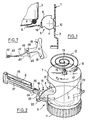
- a device 5 for counting cycles of exceeding a predetermined temperature threshold.
- this device 5 comprises an element 6 sensitive to heat capable of changing shape when the temperature exceeds a certain threshold T, arranged so as to substantially resume its initial shape when the temperature drops to the below said threshold, a signaling element 7 intended to count the number of exceedances of said threshold and comprising at least one toothed sector 8, and means for turning the toothed sector 8 by one notch during the deformation of the element 6 heat sensitive.
- the signaling element 7 is, as shown, a cylinder 7, coaxial with the toothed sector 8, the axis of which is horizontal when the fryer is placed on a horizontal plane.
- a portion of a propeller 9 which passes before a manhole 10 formed in the skirt 2 of the fryer 1 (see FIG. 1), and which allows the user of this fryer to follow the number uses of it, for example to change the frying oil and / or the odor filter of this fryer in good time.
- the cylinder 7 also includes a knurled sector 11 of the same axis which is flush with the external surface of the skirt 2 by the sight 10 and makes it possible to turn the cylinder 7 to reset the device 5 and replace the start of the propeller 9 in front of the look 10.
- This rotation of the cylinder 7 also makes it possible to re-tension a spiral spring 12 whose inner end 13 is inserted into a slot 14 formed in a pin 15 of the cylinder 7, and whose outer end 16 is inserted in a fixed cleat 17 integral skirt 2.
- the sector 8 is an escapement wheel sector known in watchmaking, associated with an anchor escapement 18.
- the function of this mechanism is not to maintain the rocking movement of a pendulum, the traces of the teeth of the sector and of the pallets of the anchor are such that only the escape function is ensured.
- the device 5 comprises means for tilting the anchor 18 in its first rest position (see FIG. 5) when the temperature is below said threshold T and for tilting the exhaust in its second position (see FIG. 6) when the temperature reached and exceeds said threshold.
- the anchor 18 pivots about an axis 19 parallel to the axis of the cylinder 7 and carries, projecting from its arms 20 which pass under the toothed sector 8, two teeth 21 and 22 which alternately engage with the teeth 23 of the toothed sector 8 when said anchor 18 rocks around its axis 19.
- the anchor 18 has a head 21 comprising a radial slot 25, the function of which will be seen below.
- the element 6 sensitive to heat is, in the example shown, an elongated element of an alloy with any known shape memory, for example of a Cu-Al-Ni alloy containing 4% by weight of nickel. It is known that the conventional temperature T at the start of reverse austenitic transformation of such an alloy varies as follows as a function of the aluminum content (by weight): % Al by weight Conventional temperature T at the start of austenitic transformation (° C) 13.0 140 13.1 110 13.2 86 13.25 84
- Such an element, placed at 4 or 5 mm from the heating resistance 4 of the fryer, is approximately around 100 ° C. It is therefore necessary to choose an aluminum content close to 13.2% in such an alloy so that the element 6 passes from its curved shape, of martensitic structure, which it has at low temperature and which is shown diagrammatically in FIG. 5, to its substantially rectilinear shape, of an austenitic structure, which it has at a temperature of the order of 100 ° C. and which is represented in FIG. 6, when the fryer 1 is used.
- the above-mentioned threshold T is thus close 85 or 90 ° C.
- an element 6 is preferably used associated with an opposing spring 26 which resists without opposing its deformation when the temperature reaches and exceeds the aforementioned threshold T, and which exerts on it a constraint forcing it to resume its initial shape when returning to ordinary temperature.
- this element 6 deforms to take the shape corresponding to its austenitic structure, providing work. This work makes it possible in particular to overcome the antagonistic force of the spring 26.
- this so-called reverse transformation takes place completely within a relatively narrow temperature range, so that the element 6 is capable of reliably, reproducibly and durably counting the successive uses of the fryer 1. It it should be noted that this temperature level, of the order of 80 to 100 ° C., is particularly well suited to shape memory alloys.
- the heat-sensitive element 6 is an elongated element nested in a leaf spring 26 so that a middle part 27 of the element 6 is on a first side of the blade 26 and that the two branches 28, 29 starting from this central part 27 pass respectively through two openings 30, 31 of the blade 26 so that the ends 32, 33 of these branches 28, 29 are located on the other side of the blade 26 relative to the middle part 27 of the element 6.
- the element 6 is thus blocked in the blade 26, and no machining, drilling, forming operation is necessary for its fixing.
- the element 6 can thus be simply cut from a plate or be a section of flat wire, and is therefore relatively inexpensive.
- the blade 26 is embedded in a support 34 (see FIG. 3) at one of its ends 35 and at its other free end 36 which urges a second leaf spring 37 of which a first end 38 is also embedded in a support and whose other end 39 is slidably embedded in the slot 25 of the head 24 of the anchor 18.
- a support 34 see FIG. 3
- the first blade 26 forces the second blade 37 to deform and to tilt the anchor 18 around its axis 19.
- the two blades 26 and 37 are in one piece and constitute the two branches of a single blade embedded in a support 40 (see Figures 5 and 6).
- the element 6 in shape memory alloy has its curved shape which corresponds to its martensitic structure.
- the blades 26 and 37 are substantially rectilinear.
- the anchor 18 has as axis of symmetry the axis 41 in dashed lines which connects the axes 19 and 40.
- the free end 36 of the blade 26 is substantially on this axis 41.
- the anchor 18 is tilted in the direction of the arrow F1, clockwise in the figure, the tooth 21 being in abutment on the side of a tooth 23 of the toothed sector 8.
- the spiral spring 12 tends to rotate the cylinder 7 in the direction of the arrow F2, that is to say clockwise in the figure, and the teeth 21, 22, 23 are tilted so that this position is stable.
- the element 6 made of a shape memory alloy placed close to the resistor 4 is subjected to a temperature which increases progressively passing through the temperature T at the start of reverse austenitic transformation, and continues to raise to a maximum temperature of the order of 130 ° C.
- the element 6 deforms relatively quickly to take the substantially rectilinear shape shown in FIG. 6, and which corresponds to its structure austenitic.
- the ends 32 and 33 of the element 6 force the blade 26 to take the curved shape shown in FIG. 6, and the end 36 of the blade 26 pressing on the blade 37 causes the anchor 18 to tilt in the direction of the arrow F3 until the tooth 22 of the anchor is in contact with the side of the tooth corresponding 23 of the toothed sector 8.
- the cylinder thus rotates one notch in the direction of arrow F2.
- the temperature drops and the element 6 resumes its shape shown in FIG. 5 under the stress exerted by the blades 26 and 37, the drum still rotating a notch in the direction F2.
- the cylinder 7 can be reset by actuating the knurled sector 11 in the opposite direction to the rotation resulting from the escapement, that is to say the counterclockwise direction in the figure. This reset also has the function of resetting the spiral spring 12 under maximum tension.
- Element 6 could be replaced by a bimetallic strip fulfilling the same functions and designed to deform at the temperatures involved.
- the shape memory alloy element is approximately 25 mm. Made using a bimetallic blade, it should be at least 50 mm long.
- the heat-sensitive element 42 has a first end 43 embedded in a fixed support 44 and at its other end 45 coupled to the anchor 18 by means 46 capable of passing the exhaust 18 from its first to its second position when the temperature reaches said threshold T and the element 42 sensitive to heat deforms, and vice versa.
- This element 42 made of a shape memory alloy, has undergone a thermomechanical education treatment allowing it to substantially resume its initial shape without the assistance of a spring such as the blade 26. It is thus possible to remove the blades 26 and 37 and directly control the tilting of the anchor 18 by this element 42.
- connection between the element 42 and the anchor 18 takes place for example by a crescent opening 46 cut at the end of the head of the anchor and between the points of which the end 45 of the element 42.
- the only transformation of element 42 at the temperature threshold T is sufficient to cause the anchor 18 to tilt from its position at ordinary temperature, represented in solid lines, to its position at high temperature, represented in dashed lines. the figure.
- a helical spring arranged concentrically with the axis of rotation of the cylinder and disposed either in the cylinder itself. - even, or in its extension.
- the blades 26, 37 could also be replaced by equivalent means, for example coil springs, the anchor escapement 18 by an exhaust of another type, and more generally the various components and characteristics of the device according to the invention by equivalent elements.
- the device has been described in the context of its use on a fryer: it is obviously possible to use this device on all kinds of appliances, culinary or not, the use of which is accompanied by thermal phenomena and cycles liable to be counted , the heat sensitive element being chosen so as to be adapted to the temperatures actually involved in each particular use.
Landscapes
- Physics & Mathematics (AREA)
- General Physics & Mathematics (AREA)
- Frying-Pans Or Fryers (AREA)
- Control Of Temperature (AREA)
- Control Of Combustion (AREA)
- Control Of High-Frequency Heating Circuits (AREA)
- Investigating Or Analyzing Materials Using Thermal Means (AREA)
- Electric Clocks (AREA)
- Cookers (AREA)
Claims (9)
- Wärmendes Küchengerät, das eine Vorrichtung (5) aufweist, um die Anzahl Benützungen dieses obigen Geräts zu zählen, wobei die obige Vorrichtung (5) folgendes umfasst:- ein wärmeempfindliches und unter dem Einfluss der Temperatur formveränderliches Element (6), wobei das obige Element (6) ein an einem festen Punkt (44) eingespanntes Ende hat und mit einer gegenwirkenden Feder (26) verknüpft ist.- ein die Anzahl Benützungzyklen meldendes Element in Form eines Zylinders (7),- einen Rändelrad-Abschnitt (11) mit der gleichen Achse wie der Zylinder (7),- Mittel zum Verbinden des Elements (6) mit dem meldenden Element (7), wobei die obigen Mittel wenigstens einen zum Zylinder (7) koaxialen Zahnrad-Abschnitt (8) umfassen, der mit einer um seine Achse (19) schwenkenden Ankerhemmung (18) verbunden ist, wobei die Ankerhemmung (18) an das andere Ende (45) des Elements (6) angekoppelt ist,- eine als Antriebselement auf den Zylinder (7) wirkende Feder (12),wobei das empfindliche Element (6) seine Form unter dem Einfluss der Heizung im Laufe eines Zyklus verändert und die Feder (26) bei Erreichen und Überschreiten eines Temperatur-Grenzwertes (T), ohne gegen die Verformung des Elements (6) zu wirken, widersteht und Druck auf ihn ausübt, wodurch sie ihn zwingt, bei Rückkehr zur üblichen Temperatur wieder in seine ursprüngliche Form anzunehmen, während sich das meldende Element (7) im Laufe des gleichen Zyklus durch die Mittel, die es mit dem empfindlichen Element (6) verbinden, einen Schritt weiterdreht.
- Wärmendes Küchengerät gemäss dem Anspruch 1, dadurch gekennzeichnet, dass das Rücksetzen den Zylinder (7) in Drehung versetzt und sich die Feder (12) wieder spannen lässt.
- Wärmendes Küchengerät gemäss einem der Ansprüche 1 oder 2, dadurch gekennzeichnet, dass das wärmeempfindliche Element (6) ein in einer Blattfeder eingebettetes längliches Element (26) ist, wobei ein mittleres Teil des Elements (6) auf einer ersten Seite liegt (26), während die beiden Zweige (28,29), die von diesem mittleren Teil (27) ausgehen, in zwei jeweilige Öffnungen (30, 31) des Blattes (26) laufen und die Enden (32,35) dieser Zweige sich bezüglich des mittleren Teils (27) des Elements (6) auf der anderen Seite des Blattes (26) befinden.
- Wärmendes Küchengerät gemäss dem Anspruch 3, dadurch gekennzeichnet, dass das Blatt (26) in einem Träger (34) an einem seiner Enden (35) eingepannt ist, dass sein anderes freies Ende (36) ein zweites Federblatt (37) beansprucht, dessen erstes Ende (38) auch in einem Träger (34) eingepannt ist und dessen anderes Ende (39) mit der Hemmung (18) verbunden ist, und dass, wenn das wärmeempfindliche Element (6) sich verbiegt, das erste Blatt (26) das zweite Blatt (37) sich verbiegen und die Hemmung (18) sich um ihre Achse (19) drehen lässt.
- Wärmendes Küchengerät gemäss dem Anspruch 4, dadurch gekennzeichnet, dass das andere Ende (39) des zweiten Blattes (37) in der Hemmung (18) eingespannt ist.
- Wärmendes Küchengerät gemäss einem der vorhergehenden Ansprüche, dadurch gekennzeichnet, dass das wärmeempfindliche Element (42) ein erstes in einem festen Träger (44) eingespanntes Ende (43) und ein anderes Ende (45) aufweist, das mit der Hemmung (18) durch Mittel (46) verbunden ist, um die Hemmung (18) aus ihrer ersten Position in ihre zweite Position bewegen zu lassen, wenn sich das wärmeempfindliche Element (42) verformt, und umgekehrt.
- Wärmendes Küchengerät gemäss einem der vorhergehenden Ansprüche, dadurch gekennzeichnet, dass das wärmeempfindliche Element (6) ein Bimetallstreifen oder eine Formgedächtnislegierung ist.
- Wärmendes Küchengerät gemäss dem Anspruch 7, wobei das wärmeempfindliche Element (6) eine Formgedächtnislegierung ist, dadurch gekennzeichnet, dass dieses Element durch eine thermische und mechanische Behandlung trainiert worden ist und nach jedem Zyklus wieder von selbst seine ursprüngliche Form annimmt.
- Wärmendes Küchengerät wie etwa eine Friteuse (1), dadurch gekennzeichnet, dass es eine Vorrichtung (5) gemäss einem der Ansprüche 1 bis 8 aufweist, wobei das wärmeempfindliche Element (6) dieser Vorrichtung (5) in unmittelbarer Nähe der Wärmequelle (4) angelegt ist.
Applications Claiming Priority (2)
| Application Number | Priority Date | Filing Date | Title |
|---|---|---|---|
| FR9104174 | 1991-04-05 | ||
| FR9104174A FR2674955B1 (fr) | 1991-04-05 | 1991-04-05 | Dispositif pour compter des cycles de temperature, et appareil comportant un tel dispositif. |
Publications (2)
| Publication Number | Publication Date |
|---|---|
| EP0508868A1 EP0508868A1 (de) | 1992-10-14 |
| EP0508868B1 true EP0508868B1 (de) | 1996-11-20 |
Family
ID=9411526
Family Applications (1)
| Application Number | Title | Priority Date | Filing Date |
|---|---|---|---|
| EP92400946A Expired - Lifetime EP0508868B1 (de) | 1991-04-05 | 1992-04-03 | Zyklenzählvorrichtung für das Überschreiten einer bestimmten Temperaturschwelle und Heizungsapparat mit so einer Vorrichtung |
Country Status (5)
| Country | Link |
|---|---|
| EP (1) | EP0508868B1 (de) |
| AT (1) | ATE145478T1 (de) |
| DE (2) | DE69215262T2 (de) |
| ES (1) | ES2038110T3 (de) |
| FR (1) | FR2674955B1 (de) |
Families Citing this family (1)
| Publication number | Priority date | Publication date | Assignee | Title |
|---|---|---|---|---|
| GB9815724D0 (en) * | 1998-07-21 | 1998-09-16 | Rigibore Ltd | Actuator and positioning device |
Family Cites Families (4)
| Publication number | Priority date | Publication date | Assignee | Title |
|---|---|---|---|---|
| DE1274259B (de) * | 1961-03-01 | 1968-08-01 | Siemens Elektrogeraete Gmbh | Brotroester |
| JPS5948314B2 (ja) * | 1981-10-30 | 1984-11-26 | 学校法人 早稲田大学 | 固相ヒ−トエンジン |
| JPH0139909Y2 (de) * | 1984-11-07 | 1989-11-30 | ||
| US4684913A (en) * | 1986-09-05 | 1987-08-04 | Raychem Corporation | Slider lifter |
-
1991
- 1991-04-05 FR FR9104174A patent/FR2674955B1/fr not_active Expired - Fee Related
-
1992
- 1992-04-03 AT AT92400946T patent/ATE145478T1/de active
- 1992-04-03 DE DE69215262T patent/DE69215262T2/de not_active Expired - Fee Related
- 1992-04-03 DE DE199292400946T patent/DE508868T1/de active Pending
- 1992-04-03 EP EP92400946A patent/EP0508868B1/de not_active Expired - Lifetime
- 1992-04-03 ES ES92400946T patent/ES2038110T3/es not_active Expired - Lifetime
Also Published As
| Publication number | Publication date |
|---|---|
| ATE145478T1 (de) | 1996-12-15 |
| DE69215262T2 (de) | 1997-05-15 |
| FR2674955B1 (fr) | 1995-05-24 |
| ES2038110T1 (es) | 1993-07-16 |
| EP0508868A1 (de) | 1992-10-14 |
| ES2038110T3 (es) | 1997-01-16 |
| DE508868T1 (de) | 1993-05-19 |
| FR2674955A1 (fr) | 1992-10-09 |
| DE69215262D1 (de) | 1997-01-02 |
Similar Documents
| Publication | Publication Date | Title |
|---|---|---|
| CA2231333C (fr) | Friteuse a cuve amovible | |
| EP0406750A1 (de) | Scharnier für den Behälterdeckel eines Kochgerätes | |
| CH690973A5 (fr) | Pièce d'horlogerie dont le mécanisme est entraîné par des moyens mécaniques et comprenant un dispositif d'indication de réserve de marche. | |
| EP0508868B1 (de) | Zyklenzählvorrichtung für das Überschreiten einer bestimmten Temperaturschwelle und Heizungsapparat mit so einer Vorrichtung | |
| EP3537940A1 (de) | Kochgerät zum kochen von lebensmittelprodukten | |
| EP0479673B1 (de) | Getriebemotor mit seinem Gehäuseverschlussdeckel, insbesondere für eine Scheibenwischeranlage | |
| EP2732734B1 (de) | Druckkochgerät mit verbesserter Entriegelungssteuerung | |
| FR2671400A1 (fr) | Avertisseur de niveau de temperature pour appareil menager chauffant, et appareil menager chauffant comportant un tel avertisseur. | |
| FR2671874A1 (fr) | Dispositif indicateur de surcharges d'un arbre par un couple de rotation. | |
| WO2000017538A1 (fr) | Frein a tambour utilisant un rattrapage automatique de jeu a inhibition selective | |
| EP0743666B1 (de) | Regelungsthermostat, wobei in der Sonde eine Sicherheitsvorrichtung vorgesehen ist | |
| CH713437A2 (fr) | Mécanisme d'affichage sautant. | |
| FR2768320A1 (fr) | Grille-pain a remontee ralentie | |
| EP0309435B1 (de) | Elektrisches Kochgerät | |
| EP3418532A1 (de) | Vorrichtung zur regulierung des kompressionsgrads eines verbrennungsmotors | |
| EP0881654B1 (de) | Elektrische Sicherung | |
| EP0036379A1 (de) | Elektrisches Motor-Reduziergetriebe für mittels Handkurbel betätigbare Markisen und Rolläden | |
| EP0022020A1 (de) | Druckbegrenzungsventil für ein unter Druck arbeitendes Haushaltsgerät | |
| FR2682827A1 (fr) | Dispositif de securite thermique pour appareil de cuisson electrique, du type friteuse par exemple. | |
| FR2610431A1 (fr) | Totalisateur mecanique, en particulier pour vehicules automobiles | |
| EP1143838A1 (de) | Elektrisches fritiergerät | |
| CH376796A (fr) | Dispositif de fermeture automatique d'une porte | |
| FR2772462A1 (fr) | Dispositif automatique d'extinction d'un bruleur | |
| CH639034A5 (en) | Windscreen-wiper arm particularly for motor vehicles | |
| WO2000016592A1 (fr) | Resistance de chauffe a deformation thermique angulaire pour bouilloire et controle de chauffe a sec associe |
Legal Events
| Date | Code | Title | Description |
|---|---|---|---|
| PUAI | Public reference made under article 153(3) epc to a published international application that has entered the european phase |
Free format text: ORIGINAL CODE: 0009012 |
|
| 17P | Request for examination filed |
Effective date: 19920408 |
|
| AK | Designated contracting states |
Kind code of ref document: A1 Designated state(s): AT BE CH DE ES GB IT LI NL |
|
| ITCL | It: translation for ep claims filed |
Representative=s name: BARZANO' E ZANARDO ROMA S.P.A. |
|
| TCNL | Nl: translation of patent claims filed | ||
| GBC | Gb: translation of claims filed (gb section 78(7)/1977) | ||
| TCAT | At: translation of patent claims filed | ||
| DET | De: translation of patent claims | ||
| REG | Reference to a national code |
Ref country code: ES Ref legal event code: BA2A Ref document number: 2038110 Country of ref document: ES Kind code of ref document: T3 |
|
| 17Q | First examination report despatched |
Effective date: 19950524 |
|
| GRAG | Despatch of communication of intention to grant |
Free format text: ORIGINAL CODE: EPIDOS AGRA |
|
| GRAH | Despatch of communication of intention to grant a patent |
Free format text: ORIGINAL CODE: EPIDOS IGRA |
|
| GRAH | Despatch of communication of intention to grant a patent |
Free format text: ORIGINAL CODE: EPIDOS IGRA |
|
| GRAA | (expected) grant |
Free format text: ORIGINAL CODE: 0009210 |
|
| ITF | It: translation for a ep patent filed | ||
| AK | Designated contracting states |
Kind code of ref document: B1 Designated state(s): AT BE CH DE ES GB IT LI NL |
|
| PG25 | Lapsed in a contracting state [announced via postgrant information from national office to epo] |
Ref country code: AT Effective date: 19961120 |
|
| REF | Corresponds to: |
Ref document number: 145478 Country of ref document: AT Date of ref document: 19961215 Kind code of ref document: T |
|
| REG | Reference to a national code |
Ref country code: CH Ref legal event code: NV Representative=s name: KIRKER & CIE SA |
|
| GBT | Gb: translation of ep patent filed (gb section 77(6)(a)/1977) |
Effective date: 19961125 |
|
| REF | Corresponds to: |
Ref document number: 69215262 Country of ref document: DE Date of ref document: 19970102 |
|
| REG | Reference to a national code |
Ref country code: ES Ref legal event code: FG2A Ref document number: 2038110 Country of ref document: ES Kind code of ref document: T3 |
|
| PGFP | Annual fee paid to national office [announced via postgrant information from national office to epo] |
Ref country code: GB Payment date: 19970326 Year of fee payment: 6 |
|
| PGFP | Annual fee paid to national office [announced via postgrant information from national office to epo] |
Ref country code: NL Payment date: 19970430 Year of fee payment: 6 |
|
| PGFP | Annual fee paid to national office [announced via postgrant information from national office to epo] |
Ref country code: CH Payment date: 19970501 Year of fee payment: 6 |
|
| PGFP | Annual fee paid to national office [announced via postgrant information from national office to epo] |
Ref country code: BE Payment date: 19970515 Year of fee payment: 6 |
|
| PLBE | No opposition filed within time limit |
Free format text: ORIGINAL CODE: 0009261 |
|
| STAA | Information on the status of an ep patent application or granted ep patent |
Free format text: STATUS: NO OPPOSITION FILED WITHIN TIME LIMIT |
|
| 26N | No opposition filed | ||
| PG25 | Lapsed in a contracting state [announced via postgrant information from national office to epo] |
Ref country code: GB Free format text: LAPSE BECAUSE OF NON-PAYMENT OF DUE FEES Effective date: 19980403 |
|
| PGFP | Annual fee paid to national office [announced via postgrant information from national office to epo] |
Ref country code: ES Payment date: 19980421 Year of fee payment: 7 |
|
| PG25 | Lapsed in a contracting state [announced via postgrant information from national office to epo] |
Ref country code: LI Free format text: LAPSE BECAUSE OF NON-PAYMENT OF DUE FEES Effective date: 19980430 Ref country code: CH Free format text: LAPSE BECAUSE OF NON-PAYMENT OF DUE FEES Effective date: 19980430 Ref country code: BE Free format text: LAPSE BECAUSE OF NON-PAYMENT OF DUE FEES Effective date: 19980430 |
|
| PGFP | Annual fee paid to national office [announced via postgrant information from national office to epo] |
Ref country code: DE Payment date: 19980528 Year of fee payment: 7 |
|
| BERE | Be: lapsed |
Owner name: S.A. SEB Effective date: 19980430 |
|
| PG25 | Lapsed in a contracting state [announced via postgrant information from national office to epo] |
Ref country code: NL Free format text: LAPSE BECAUSE OF NON-PAYMENT OF DUE FEES Effective date: 19981101 |
|
| GBPC | Gb: european patent ceased through non-payment of renewal fee |
Effective date: 19980403 |
|
| REG | Reference to a national code |
Ref country code: CH Ref legal event code: PL |
|
| NLV4 | Nl: lapsed or anulled due to non-payment of the annual fee |
Effective date: 19981101 |
|
| PG25 | Lapsed in a contracting state [announced via postgrant information from national office to epo] |
Ref country code: ES Free format text: LAPSE BECAUSE OF EXPIRATION OF PROTECTION Effective date: 19990405 |
|
| PG25 | Lapsed in a contracting state [announced via postgrant information from national office to epo] |
Ref country code: DE Free format text: LAPSE BECAUSE OF NON-PAYMENT OF DUE FEES Effective date: 20000201 |
|
| REG | Reference to a national code |
Ref country code: ES Ref legal event code: FD2A Effective date: 20010601 |
|
| PG25 | Lapsed in a contracting state [announced via postgrant information from national office to epo] |
Ref country code: IT Free format text: LAPSE BECAUSE OF NON-PAYMENT OF DUE FEES Effective date: 20050403 |