EP0508331B1 - Locking element especially for clamps - Google Patents
Locking element especially for clamps Download PDFInfo
- Publication number
- EP0508331B1 EP0508331B1 EP92105848A EP92105848A EP0508331B1 EP 0508331 B1 EP0508331 B1 EP 0508331B1 EP 92105848 A EP92105848 A EP 92105848A EP 92105848 A EP92105848 A EP 92105848A EP 0508331 B1 EP0508331 B1 EP 0508331B1
- Authority
- EP
- European Patent Office
- Prior art keywords
- pin
- screw bolt
- locking
- connecting element
- screw
- Prior art date
- Legal status (The legal status is an assumption and is not a legal conclusion. Google has not performed a legal analysis and makes no representation as to the accuracy of the status listed.)
- Expired - Lifetime
Links
- 239000007787 solid Substances 0.000 claims description 4
- 238000010276 construction Methods 0.000 claims description 3
- 238000000034 method Methods 0.000 description 5
- 238000009434 installation Methods 0.000 description 2
- 238000004519 manufacturing process Methods 0.000 description 2
- 239000008186 active pharmaceutical agent Substances 0.000 description 1
- 230000001419 dependent effect Effects 0.000 description 1
- 230000002349 favourable effect Effects 0.000 description 1
- 238000003466 welding Methods 0.000 description 1
Images
Classifications
-
- F—MECHANICAL ENGINEERING; LIGHTING; HEATING; WEAPONS; BLASTING
- F16—ENGINEERING ELEMENTS AND UNITS; GENERAL MEASURES FOR PRODUCING AND MAINTAINING EFFECTIVE FUNCTIONING OF MACHINES OR INSTALLATIONS; THERMAL INSULATION IN GENERAL
- F16L—PIPES; JOINTS OR FITTINGS FOR PIPES; SUPPORTS FOR PIPES, CABLES OR PROTECTIVE TUBING; MEANS FOR THERMAL INSULATION IN GENERAL
- F16L3/00—Supports for pipes, cables or protective tubing, e.g. hangers, holders, clamps, cleats, clips, brackets
- F16L3/08—Supports for pipes, cables or protective tubing, e.g. hangers, holders, clamps, cleats, clips, brackets substantially surrounding the pipe, cable or protective tubing
- F16L3/12—Supports for pipes, cables or protective tubing, e.g. hangers, holders, clamps, cleats, clips, brackets substantially surrounding the pipe, cable or protective tubing comprising a member substantially surrounding the pipe, cable or protective tubing
- F16L3/137—Supports for pipes, cables or protective tubing, e.g. hangers, holders, clamps, cleats, clips, brackets substantially surrounding the pipe, cable or protective tubing comprising a member substantially surrounding the pipe, cable or protective tubing and consisting of a flexible band
-
- F—MECHANICAL ENGINEERING; LIGHTING; HEATING; WEAPONS; BLASTING
- F16—ENGINEERING ELEMENTS AND UNITS; GENERAL MEASURES FOR PRODUCING AND MAINTAINING EFFECTIVE FUNCTIONING OF MACHINES OR INSTALLATIONS; THERMAL INSULATION IN GENERAL
- F16L—PIPES; JOINTS OR FITTINGS FOR PIPES; SUPPORTS FOR PIPES, CABLES OR PROTECTIVE TUBING; MEANS FOR THERMAL INSULATION IN GENERAL
- F16L3/00—Supports for pipes, cables or protective tubing, e.g. hangers, holders, clamps, cleats, clips, brackets
- F16L3/08—Supports for pipes, cables or protective tubing, e.g. hangers, holders, clamps, cleats, clips, brackets substantially surrounding the pipe, cable or protective tubing
- F16L3/12—Supports for pipes, cables or protective tubing, e.g. hangers, holders, clamps, cleats, clips, brackets substantially surrounding the pipe, cable or protective tubing comprising a member substantially surrounding the pipe, cable or protective tubing
Definitions
- the invention relates to a connecting part with the features of the preamble of claim 1.
- connecting parts relate to clamps, by means of which pipes accommodated in them can be fixed.
- a screw bolt passes through two pins provided with recesses in the form of bores, which are wrapped by a clamp band. If the tube cannot be inserted laterally into the clamp, the screw bolt must be removed from the recesses and the elastic clamp band is pulled apart until the tube enters the opening between fits through the two opposite pegs, in order to be subsequently enclosed in the clamp by the clamp band. To close the clamp, the screw bolt is then inserted through the recesses in the pin and tightened with a suitable tool until the pipe is securely enclosed by the clamp.
- the screw bolt When the pipe is received, the screw bolt can remain in the recess of one of the two pins and is pivotably arranged there for a corresponding length compensation of the clamp depending on the diameter range of the pipe to be received by means of the assigned pin.
- the longitudinal adjustment is achieved by means of a threaded nut that can be screwed onto the screw bolt.
- the known connecting part can therefore only be fully opened when the threaded nut is removed and when the screw bolt is at least led out of the bore with its free end, so that opening and closing is difficult and takes a lot of time.
- a connecting part for connecting two ends which partially encloses a pin in the region of one end and which has a longitudinally adjustable, pivotable engaging part which engages in the U-shaped groove of a leg piece forming a recess, which is arranged at the other end of the connecting part and firmly connected thereto.
- the engaging part in the form of a screw bolt can be fixed in the leg piece by means of a sleeve-like nut for closing the closure part.
- a connecting part is known in which the two ends protrude outdoors in a web-like manner and essentially at right angles.
- the closure part is fixed, in particular when high closing forces are applied, the webs may bend and the connection part may become involuntarily detached.
- the closure part of DE-OS 33 46 423 contrary to the closure part according to DE-PS 35 22 497, already has a pivotable engagement part in the form of a screw bolt, which ensures that the connection can be released quickly; the swivel mechanism developed for this purpose, which includes one of the two webs, is complicated in construction and therefore expensive to manufacture.
- a connecting part is known, the ends of which are folded over to form angle pieces and connected to the remaining connecting part by means of a stitch.
- the elbows formed by the turning over are penetrated by a longitudinally adjustable engaging part in the form of a screw bolt.
- the engaging part has to be completely loosened, which is time-consuming.
- EP-A-0 286 561 discloses a connecting part of the same type, in which both pins are designed as hollow cylinders, the pin which is intended to be latched to the screw head of the screw bolt having a continuous longitudinal slot.
- the latching part in this sleeve-like pin consists of a circular recess which is enlarged relative to the groove and into which a widening of the screw bolt or the entire screw body which is provided for this purpose and with a diameter engages.
- the widening of the screw bolt is held within the pin by the undercut formed by the latching part and groove, with a support washer, which in the known solution is between the hexagon head and the widening is arranged, outside of the pin with it takes over the support.
- the screw head of the screw bolt with its support washer must be arranged outside the associated pin with the locking part, with the result that the known clamp builds up large in this area, which is disadvantageous in particular for cramped installation conditions for assembly . With large holding forces, the pin is deformed, particularly in the area of the latching part, so that failure cannot be ruled out.
- the invention has for its object to provide an improved connection part, which is inexpensive to manufacture and which allows a cheap force application when applying high holding forces without failure.
- a related object is achieved by a connecting part with the features of claim 1.
- the pin provided with the locking part is solid and that the locking part forms a flat contact surface due to the circular recess, which can be brought into direct contact with the facing surface of the underside of the screw head for the locking process, the screw head of the screw thread directly into the assigned pin, which saves installation space and allows high holding forces to be applied, since these can be introduced without failure into the solid pin via the flat contact surface within the locking part.
- connecting part is the subject of the dependent claims.
- the connecting part according to the invention is particularly advantageously suitable for opening and closing clamps, as are shown, for example, in the applicant's unpublished DE-OS 41 11 359.4.
- the connecting part according to the invention is used to open and close an articulated band bracket clamp according to DE 41 11 359.4, which is described there in detail, so that its construction is not dealt with in more detail at this point.
- this clamp has a clamp band which is essentially circular and delimits a receiving space 12 in which a pipe (not shown) can be fixed in its position.
- the clamp band 10 has two mutually opposite ends 14 and 16, each partially a pin. 18 or 20 enclose and preferably the pin 18.20 hold axially immovable in their position in the clamp band 10.
- the clamp band 10 wrapped around the two pins 18, 20 is connected to the rest of the clamp band 10 by spot welding, forming the eyes for the pins 18, 20 to be received.
- a screw bolt is provided as the engaging part 22, which has a thread 24 at one end and a screw head 26 at its other end, which has a hexagon socket recess for the engagement of a tool.
- a threaded nut 28 can be screwed onto the thread 24 of the screw bolt 22.
- the engagement part 22 can be adjusted lengthwise by means of this threaded nut 28.
- the clamp band 10 is longitudinally divided and the pin 20, which is designed as a hollow cylinder, has a continuous recess 30 which is oval in shape and which is penetrated by the screw bolt 22.
- the pin 20 has 30 projections (not shown) in the region of its recess, which cooperate with a widening 32 of the clamp band in such a way that the pin 20 is held by the looped part of the clamp band 10 so that it can pivot about 180 °. Thanks to this pivotability, the pin 20, as shown in particular in FIG. 1, can be pivoted to a limited extent and, after the screw bolt 22 has been removed, can also be removed from the clamp band 10 by hand.
- the second pin 18 shown as a separate part in FIG. 2 is solid and has a continuous groove 34 transversely to its longitudinal direction, which opens into a latching part 36 for latching with the engaging part 22.
- the two opposite side walls of the groove 34 are flat and open into a semicircular groove bottom, the diameter of which is adapted to the diameter of the bolt 22.
- the locking part 36 is formed from a circular recess 38 in the pin 18, the diameter of which corresponds to the diameter of the screw head 26, the recess 38 forming an undercut 40 with the groove 34, into which the screw head 26 can be snapped.
- the cylindrical pin 18 has a position in the clamp band 10 that the groove 34 with its opening running transversely to the longitudinal direction of the pin 18 faces the screw bolt 22.
- the locking part 36 thus forms a flat contact surface which can be brought into contact with the surface of the underside of the screw head 26 facing it for the locking process.
- the screw bolt 22 is screwed on by means of an Allen key, the threaded nut 28 remaining in abutment with the part of the clamp band 10 wound around it with two of its surfaces which are intended for the engagement of a tool.
- the screw bolt 22 is screwed on until the screw head 26 disengages from the undercut 40 of the locking part 36. Then the screw bolt 22 can be pivoted upward against the arrow direction shown in FIG. 1 by means of the pin 20.
- the screw bolt 22 can be pushed completely through the recess 30 of the pin 20 until the screw head 26 comes into contact with the deflected part of the clamp band 10.
- the elastic clamp band can then be widened further to accommodate or remove a tube (not shown) that is already in the receiving space 12.
- the screw bolt 22 is returned to its position shown in FIG. 1 above, the two clamp ends 14, 16 being bent toward one another.
- the screw head 26 comes into contact with the pin 18. Due to the inherent tension of the clamp band 10 that wants to open, the screw head 26 is pulled into the latching part 36 and the screw head 26 comes into contact with the undercut 40.
- the screw bolt 22 is then tightened via the hexagon socket in the screw head 26, the threaded nut 28 with two of its Tool engagement surfaces in contact with the clamp band 10 and thus serves as a lock nut.
- the clamp can be provided with profile rubber pieces 42 which are U-shaped in cross section. If the mutually facing ends of the two profiled rubber pieces 42 comprise the lower part of the two pins 18, 20 (not shown), they can thus be held in their axial position within the looped area of the clamp band 10.
- the closure part according to the invention need not be limited to the use for clamps. For example, chain links or flat, band-shaped, link-like parts could also be connected to one another.
Landscapes
- Engineering & Computer Science (AREA)
- General Engineering & Computer Science (AREA)
- Mechanical Engineering (AREA)
- Clamps And Clips (AREA)
- Insertion Pins And Rivets (AREA)
- Supports For Pipes And Cables (AREA)
- Snaps, Bayonet Connections, Set Pins, And Snap Rings (AREA)
- Sheet Holders (AREA)
- Load-Engaging Elements For Cranes (AREA)
- Braking Arrangements (AREA)
- Pivots And Pivotal Connections (AREA)
Abstract
Description
Die Erfindung betrifft ein Verbindungsteil mit den Merkmalen des Oberbegriffs des Anspruches 1.The invention relates to a connecting part with the features of the preamble of claim 1.
Im Handel erhältliche, bekannte Verbindungsteile betreffen Schellen, mittels denen sich in ihnen aufgenommene Rohre festlegen lassen. Bei diesen bekannten Verbindungsteilen durchgreift ein Schraubenbolzen zwei mit Ausnehmungen in Form von Bohrungen versehene Zapfen, die von einem Schellenband umschlungen sind. Sofern das Rohr sich nicht seitlich in die Schelle einführen läßt, ist der Schraubenbolzen aus den Ausnehmungen zu entfernen und das elastische Schellenband wird so lange auseinandergezogen, bis das Rohr in die Öffnung zwischen den beiden einander gegenüberliegenden Zapfen hindurchpaßt, um anschließend in der Schelle von dem Schellenband umschlossen aufgenommen zu sein. Zum Schließen der Schelle wird dann der Schraubenbolzen durch die Ausnehmungen in den Zapfen wieder hindurchgesteckt und mit geeignetem Werkzeug so lange angezogen, bis das Rohr sicher von der Schelle umschlossen ist. Bei der Aufnahme des Rohres kann der Schraubenbolzen in der Ausnehmung einer der beiden Zapfen verbleiben und ist dort für einen entsprechenden Längenausgleich der Schelle in Abhängigkeit von dem Durchmesserbereich des aufzunehmenden Rohres mittels dem zugeordneten Zapfen schwenkbar angeordnet. Die Längsverstellung ist mittels einer auf den Schraubenbolzen aufschraubbaren Gewindemutter erreicht. Das bekannte Verbindungsteil läßt sich mithin nur vollständig öffnen, wenn die Gewindemutter entfernt ist und wenn der Schraubenbolzen zumindest aus der Bohrung mit seinem freien Ende herausgeführt ist, so daß das Öffnen und Schließen erschwert ist und viel Zeit benötigt.Commercially available connecting parts relate to clamps, by means of which pipes accommodated in them can be fixed. In these known connecting parts, a screw bolt passes through two pins provided with recesses in the form of bores, which are wrapped by a clamp band. If the tube cannot be inserted laterally into the clamp, the screw bolt must be removed from the recesses and the elastic clamp band is pulled apart until the tube enters the opening between fits through the two opposite pegs, in order to be subsequently enclosed in the clamp by the clamp band. To close the clamp, the screw bolt is then inserted through the recesses in the pin and tightened with a suitable tool until the pipe is securely enclosed by the clamp. When the pipe is received, the screw bolt can remain in the recess of one of the two pins and is pivotably arranged there for a corresponding length compensation of the clamp depending on the diameter range of the pipe to be received by means of the assigned pin. The longitudinal adjustment is achieved by means of a threaded nut that can be screwed onto the screw bolt. The known connecting part can therefore only be fully opened when the threaded nut is removed and when the screw bolt is at least led out of the bore with its free end, so that opening and closing is difficult and takes a lot of time.
Aus der US-PS 4 445 255 ist ein Verbindungsteil zum Verbinden zweier Enden bekannt, , das im Bereich eines Endes teilweise einen Zapfen umschließt und das ein längsverstellbares, schwenkbares Eingreifteil aufweist, das in die eine Ausnehmung bildende U-förmige Nut eines Schenkelstückes eingreift, das am anderen Ende des Verbindungsteiles und mit diesem fest verbunden angeordnet ist. Das Eingreifteil in Form eines Schraubenbolzens läßt sich mittels einer hülsenartigen Mutter zum Schließen des Verschlußteiles in dem Schenkelstück festlegen. Beim Anziehen der Mutter sowie beim Auftreten von Vibrationen am bekannten Verschlußteil ist nicht auszuschließen, daß das Verschlußteil sich unfreiwillig öffnet und die herzustellende Verbindung zwischen den beiden Enden des Verbindungsteiles sich löst und damit das aufzunehmende Teil freigegeben wird.From US Pat. No. 4,445,255 a connecting part for connecting two ends is known, which partially encloses a pin in the region of one end and which has a longitudinally adjustable, pivotable engaging part which engages in the U-shaped groove of a leg piece forming a recess, which is arranged at the other end of the connecting part and firmly connected thereto. The engaging part in the form of a screw bolt can be fixed in the leg piece by means of a sleeve-like nut for closing the closure part. When tightening the nut and when vibrations occur on the known closure part, it cannot be ruled out that the closure part will open involuntarily and the connection to be made between the two ends of the connection part will become loose and the part to be recorded will be released.
Durch die DE-PS 35 22 497 sowie durch die DE-DS 33 46 423 ist ein Verbindungsteil bekannt, bei dem die beiden Enden stegartig und im wesentlichen rechtwinklig ins Freie abstehen. Beim Festlegen des Verschlußteiles, insbesondere beim Aufbringen hoher Schließkräfte, kann es zum Abknicken der Stege und damit zu einem unfreiwilligen Lösen des Verbindungsteiles kommen. Zwar weist das Verschlußteil der DE-OS 33 46 423 entgegen dem Verschlußteil gemäß der DE-PS 35 22 497 bereits ein schwenkbares Eingreifteil in Form eines Schraubenbolzens auf, was eine schnelle Lösbarkeit der Verbindung gewährleistet; der hierzu entwickelte Schwenkmechanismus, der einen der beiden Stege mit einbezieht, ist aber kompliziert im Aufbau und damit teuer in der Herstellung.From DE-PS 35 22 497 and DE-DS 33 46 423 a connecting part is known in which the two ends protrude outdoors in a web-like manner and essentially at right angles. When the closure part is fixed, in particular when high closing forces are applied, the webs may bend and the connection part may become involuntarily detached. Although the closure part of DE-OS 33 46 423, contrary to the closure part according to DE-PS 35 22 497, already has a pivotable engagement part in the form of a screw bolt, which ensures that the connection can be released quickly; the swivel mechanism developed for this purpose, which includes one of the two webs, is complicated in construction and therefore expensive to manufacture.
Durch die FR-PS 2 519 405 ist ein Verbindungsteil bekannt, dessen Enden unter Bildung von Winkelstücken umgeschlagen und mit dem übrigen Verbindungsteil mittels einer Heftung verbunden sind. Die durch das Umschlagen gebildeten Winkelstücke werden von einem längsverstellbaren Eingreifteil in Form eines Schraubenbolzens durchgriffen. Um das Innere des Verbindungsteiles freizugeben, ist das Eingreifteil vollständig zu lösen, was zeitintensiv ist. Ferner kommt es bei diesem Verschlußteil ebenso wie bei den Verschlußteilen nach den beiden deutschen Dokumenten aufgrund schräg und nachgiebig angeordneter Stegteile an den Enden und/oder durch die relative Unbeweglichkeit des Schraubenbolzens zumindest zu Beginn des Schließvorganges nur zu einer unvollständigen Anlage von Schraubenkopf und/oder Schraubenmutter mit den Enden des Verbindungsteiles, was zu einer ungünstigen Krafteinleitung führt.From FR-PS 2 519 405 a connecting part is known, the ends of which are folded over to form angle pieces and connected to the remaining connecting part by means of a stitch. The elbows formed by the turning over are penetrated by a longitudinally adjustable engaging part in the form of a screw bolt. To release the inside of the connecting part, the engaging part has to be completely loosened, which is time-consuming. Furthermore, with this closure part, as with the closure parts according to the two German documents, due to the obliquely and resiliently arranged web parts at the ends and / or due to the relative immobility of the screw bolt, at least at the beginning of the closing process, the screw head and / or screw nut do not fit completely with the ends of the connecting part, which leads to an unfavorable introduction of force.
Durch die EP-A-0 286 561 ist ein gattungsgleiches Verbindungsteil bekannt, bei dem beide Zapfen hohlzylinderartig ausgebildet sind, wobei der Zapfen, der für die Verrastung mit dem Schraubenkopf des Schraubenbolzens vorgesehen ist, einen durchgehenden Längsschlitz aufweist. Das Rastteil in diesem hülsenartigen Zapfen besteht aus einer gegenüber der Nut vergrößerten, kreisförmigen Ausnehmung, in die eine hierfür vorgesehene, im Durchmesser zylindrische Verbreiterung des Schraubenbolzens oder der ganze Schraubenkorpf eingreift . Im gezeigten Ausführungsbeispiel, nach Einrasten dieser Verbreiterung des Schraubenbolzens und Anziehen desselben wird durch die entstehende Spannung im Schellenband die Verbreiterung des Schraubenbolzens von der von Rastteil und Nut gebildeten Hinterschneidung innerhalb des Zapfens gehalten, wobei eine Stützscheibe, die bei der bekannten Lösung zwischen dem Sechskantkopf und der Verbreiterung angeordnet ist, außerhalb des Zapfens unter Anlage mit ihm die Abstützung übernimmt. Mithin muß für die Funktion der bekannten Lösung der Schraubenkopf des Schraubenbolzens mit seiner Stützscheibe zwingend außerhalb des zugehörigen Zapfens mit dem Rastteil angeordnet sein, mit der Folge, daß in diesem Bereich die bekannte Schelle groß aufbaut, was insbesondere bei beengten Einbauverhältnissen für die Montage nachteilig ist. Auch kommt es bei großen Haltekräften zu Verformungen des Zapfens, insbesondere im Bereich des Rastteiles, so daß ein Versagen nicht auszuschließen ist.EP-A-0 286 561 discloses a connecting part of the same type, in which both pins are designed as hollow cylinders, the pin which is intended to be latched to the screw head of the screw bolt having a continuous longitudinal slot. The latching part in this sleeve-like pin consists of a circular recess which is enlarged relative to the groove and into which a widening of the screw bolt or the entire screw body which is provided for this purpose and with a diameter engages. In the exemplary embodiment shown, after this widening of the screw bolt has been snapped in and tightened, the widening of the screw bolt is held within the pin by the undercut formed by the latching part and groove, with a support washer, which in the known solution is between the hexagon head and the widening is arranged, outside of the pin with it takes over the support. Thus, for the function of the known solution, the screw head of the screw bolt with its support washer must be arranged outside the associated pin with the locking part, with the result that the known clamp builds up large in this area, which is disadvantageous in particular for cramped installation conditions for assembly . With large holding forces, the pin is deformed, particularly in the area of the latching part, so that failure cannot be ruled out.
Ausgehend von diesem Stand der Technik liegt der Erfindung die Aufgabe zugrunde, ein demgegenüber verbessertes Verbindungsteil zu schaffen, das kostengünstig herstellbar ist und das eine günstige Krafteinleitung bei Aufbringen hoher Haltekräfte versagensfrei ermöglicht. Eine dahingehende Aufgabe löst ein Verbindungsteil mit den Merkmalen des Anspruches 1.Based on this prior art, the invention has for its object to provide an improved connection part, which is inexpensive to manufacture and which allows a cheap force application when applying high holding forces without failure. A related object is achieved by a connecting part with the features of claim 1.
Dadurch, daß der mit dem Rastteil versehene Zapfen massiv ausgebildet ist und daß das Rastteil aufgrund der kreisförmigen Vertiefung eine eben verlaufende Anlagefläche ausbildet, die in unmittelbare Anlage mit der ihr zugewandten Fläche der Unterseite des Schraubenkopfes für den Rastvorgang bringbar ist, greift der Schraubenkopf des Schraubengewindes unmittelbar in den zugeordneten Zapfen ein, was Einbauraum spart und das Aufbringen hoher Haltekräfte erlaubt, da diese über die eben verlaufende Anlagefläche innerhalb des Rastteiles in den massiven Zapfen versagensfrei einleitbar sind.Characterized in that the pin provided with the locking part is solid and that the locking part forms a flat contact surface due to the circular recess, which can be brought into direct contact with the facing surface of the underside of the screw head for the locking process, the screw head of the screw thread directly into the assigned pin, which saves installation space and allows high holding forces to be applied, since these can be introduced without failure into the solid pin via the flat contact surface within the locking part.
Bevorzugte Ausgestaltungen des Verbindungsteiles sind Gegenstand der Unteransprüche. Das erfindungsgemäße Verbindungsteil eignet sich in besonders vorteilhafter Weise zum Öffnen und Schließen von Schellen, wie sie beispielsweise in der nicht vorveröffentlichten DE-OS 41 11 359.4 der Anmelderin dargestellt sind.Preferred embodiments of the connecting part are the subject of the dependent claims. The connecting part according to the invention is particularly advantageously suitable for opening and closing clamps, as are shown, for example, in the applicant's unpublished DE-OS 41 11 359.4.
Im folgenden wird das erfindungsgemäße Verbindungsteil anhand der Zeichnung näher erläutert.The connecting part according to the invention is explained in more detail below with reference to the drawing.
Es zeigen:
- Fig.1
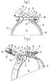
- eine Seitenansicht des in einer Schelle eingebauten Verschlußteiles;
- Fig.2
- eine perspektivische Darstellung des Verschlußteiles mit Schelle gemäß Fig.1, wobei der Zapfen mit der Nut und dem Rastteil separat dargestellt ist.
- Fig. 1
- a side view of the built-in closure part;
- Fig. 2
- a perspective view of the closure part with a clamp according to Figure 1, the pin with the groove and the locking part is shown separately.
Das erfindungsgemäße Verbindungsteil dient zum Öffnen und Verschließen einer Gelenkband-Konsolenschelle gemäß der DE 41 11 359.4, die dort im einzelnen beschrieben ist, so daß auf deren Aufbau an dieser Stelle nicht näher eingegangen wird. Diese Schelle weist als Verbindungsteil 10 im Sinne der Erfindung ein Schellenband auf, das im wesentlichen kreisförmig ausgebildet ist und einen Aufnahmeraum 12 begrenzt, in dem ein Rohr (nicht dargestellt) in seiner Lage festlegbar ist. Das Schellenband 10 weist zwei einander benachbart gegenüberliegende Enden 14 und 16 auf, die jeweils teilweise einen Zapfen. 18 bzw. 20 umschließen und die die Zapfen 18,20 vorzugsweise axial unverschiebbar in ihrer Lage im Schellenband 10 halten. Das um die beiden Zapfen 18,20 herumgeschlungene Schellenband 10 ist unter Bildung der Augen für die aufzunehmenden Zapfen 18,20 mittels einer Punktschweißung mit dem übrigen Schellenband 10 verbunden.The connecting part according to the invention is used to open and close an articulated band bracket clamp according to DE 41 11 359.4, which is described there in detail, so that its construction is not dealt with in more detail at this point. As a connecting
Als Eingreifteil 22 ist ein Schraubenbolzen vorgesehen, der an seinem einen Ende ein Gewinde 24 und an seinem anderen Ende einen Schraubenkopf 26 aufweist, der für den Eingriff eines Werkzeuges eine Innensechskant-Ausnehmung hat. Auf das Gewinde 24 des Schraubenbolzens 22 ist eine Gewindemutter 28 aufschraubbar. Mittels dieser Gewindemutter 28 läßt sich das Eingreifteil 22 längsverstellen. Im Bereich der beiden Zapfen 18 und 20 ist das Schellenband 10 längsgeteilt und der Zapfen 20, der als Hohlzylinder ausgebildet ist, weist eine durchgehende Ausnehmung 30 auf, die oval ausgebildet ist und die von dem Schraubenbolzen 22 durchgriffen ist. Der Zapfen 20 weist im Bereich seiner Ausnehmung 30 Vorsprünge (nicht dargestellt) auf, die mit einer Verbreiterung 32 des Schellenbandes derart zusammenwirken, daß der Zapfen 20 um etwa 180° schwenkbar in dem umschlungenen Teil des Schellenbandes 10 von diesem gehalten ist. Dank dieser Verschwenkbarkeit läßt sich der Zapfen 20, wie dies insbesondere die Fig.1 zeigt, begrenzt verschwenken und nach Entfernung des Schraubenbolzens 22 auch aus dem Schellenband 10 von Hand herausnehmen.A screw bolt is provided as the
Der in Fig.2 als separates Teil dargestellte zweite Zapfen 18 ist massiv ausgebildet und weist quer zu seiner Längsrichtung eine durchgehende Nut 34 auf, die in einen Rastteil 36 für die Verrastung mit dem Eingreifteil 22 mündet. Die beiden einander gegenüberliegenden Seitenwände der Nut 34 sind eben ausgebildet und münden in einen halbkreisförmigen Nutengrund, dessen Durchmesser dem Durchmesser des Schraubenbolzens 22 angepaßt ist. Das Rastteil 36 hingegen ist aus einer kreisförmigen Vertiefung 38 im Zapfen 18 gebildet, deren Durchmesser dem Durchmesser des Schraubenkopfes 26 entspricht, wobei die Vertiefung 38 mit der Nut 34 eine Hinterschneidung 40 bildet, in die der Schraubenkopf 26 einrastbar ist. Der zylindrische Zapfen 18 hat in dem Schellenband 10 eine Lage, daß die Nut 34 mit ihrer quer zur Längsrichtung des Zapfens 18 verlaufenden Öffnung dem Schraubenbolzen 22 zugewandt ist. Das Rastteil 36 bildet mithin eine eben verlaufende Anlagefläche aus, die in Anlage mit der ihr zugewandten Fläche der Unterseite des Schraubenkopfes 26 für den Rastvorgang bringbar ist.The
Zum Öffnen des Verschlusses der Schelle wird mittels eines Innensechskant-Schlüssels der Schraubenbolzen 22 aufgeschraubt, wobei die Gewindemutter 28 als Konterung mit zwei ihrer Flächen, die für den Angriff eines Werkzeuges vorgesehen sind, in Anlage mit dem umschlungenen Teil des Schellenbandes 10 verbleibt. Der Schraubenbolzen 22 wird so lange aufgeschraubt, bis der Schraubenkopf 26 außer Eingriff mit der Hinterschneidung 40 des Rastteiles 36 gerät. Dann läßt sich der Schraubenbolzen 22 entgegen der in Fig.1 dargestellten Pfeilrichtung nach oben mittels des Zapfens 20 verschwenken. Zur vollständigen Freigabe der Öffnung zwischen den beiden Zapfen 18 und 20 läßt sich der Schraubenbolzen 22 vollends durch die Ausnehmung 30 des Zapfens 20 hindurchschieben, bis der Schraubenkopf 26 in Anlage mit dem umgelenkten Teil des Schellenbandes 10 kommt. Das elastische Schellenband läßt sich dann weiter aufweiten für die Aufnahme oder das Entfernen eines bereits in dem Aufnahmeraum 12 befindlichen Rohres (nicht dargestellt). Zum Schließen des Verschlußteiles und damit der Schelle wird der Schraubenbolzen 22 wieder in seine in der Fig.1 oben dargestellte Lage zurückgebracht, wobei die beiden Schellenenden 14,16 aufeinander zugebogen werden. Nach dem anschließenden Verschwenken des Schraubenbolzens 22 in Richtung des Pfeiles in Fig.1 kommt der Schraubenkopf 26 in Anlage mit den Zapfen 18. Durch die Eigenspannung des Schellenbandes 10, das sich öffnen will, wird der Schraubenkopf 26 in das Rastteil 36 hineingezogen und der Schraubenkopf 26 kommt in Anlage mit der Hinterschneidung 40. Anschließend wird über den Innensechskant im Schraubenkopf 26 der Schraubenbolzen 22 angezogen, wobei die Gewindemutter 28 mit zwei ihrer Werkzeugangriffsflächen in Anlage mit dem Schellenband 10 ist und damit als Kontermutter dient. Der Schraubenbolzen 22 wird dann so lange angezogen, bis ein etwaig in dem Aufnahmeraum 12 befindliches Rohr (nicht dargestellt) in der Schelle festgelegt ist. Bei dem angesprochenen Spannvorgang beim Schließen des erfindungsgemäßen Verschlußteiles wird der kraftschlüssig gehaltene Zapfen 18 bedingt durch die formschlüssige Verbindung von Vertiefung 38 mit Schraubenkopf 26 in radialer Richtung gesehen derart ausgerichtet, daß die Längsachse der Nut 34 koaxial zu der Längsachse des Schraubenbolzens 22 verläuft, sofern dieser vollständig in die Nut 34 eingeschwenkt ist. Durch den kraftschlüssig gehaltenen Zapfen 18 ist dieser derart in dem umschlungenen Teil des Schellenbandes 10 gehalten, daß erst beim eigentlichen Spannvorgang mittels des Eingreifteiles 22 sich der Zapfen 18 radial und zwangsläufig derart bewegt, daß es zu der für die Krafteinleitung in das Verbindungsteil 10 günstigen koaxialen Anordnung von Nut 34 mit dem Eingreifteil 22 in Form des Schraubenbolzens kommt.To open the closure of the clamp, the
Zum Schutz des aufzunehmenden Rohres kann die Schelle, wie insbesondere Fig.1 zeigt, mit im Querschnitt U-förmig ausgebildeten Profilgummistücken 42 versehen sein. Sofern die einander zugekehrten Enden der beiden Profilgummistücke 42 den unteren Teil der beiden Zapfen 18,20 (nicht dargestellt) umfassen, können diese somit in ihrer axialen Lage innerhalb des umschlungenen Bereiches des Schellenbandes 10 gehalten werden. Das erfindungsgemäße Verschlußteil braucht nicht auf die Anwendung für Schellen beschränkt zu sein. So ließen sich beispielsweise Kettenglieder oder ebene, bandförmige, gliedartige Teile ebenso miteinander verbinden.To protect the pipe to be received, the clamp, as shown in particular in FIG. 1, can be provided with
Claims (4)
- Connecting element, which in the region of its two ends (14, 16) surrounds at least partly respectively one pin (18, 20), and with a closure element between the two ends (14, 16) with a longitudinally adjustable, tilting engagement part (22), which is formed by a screw bolt and which engages in recesses (30, 34) of the two pins (18, 20), the recess of one pin (18) being constructed as a groove (34), which comprises a locking part (36) for locking with the screw head (26) of the screw bolt, which can be pivoted into the groove (34), which with the locking part (36) forms a back taper (40), the locking part (36) with its back taper (40) being formed from a circular recess (38) in the pin (18), whereof the diameter corresponds to the diameter of the screw head (26), characterized in that the pin (18) provided with the locking part (36) has a solid construction and that the locking part (36) forms an abutment surface (5c) extending in a flat manner, which can be brought into abutment with the facing surface of the underside of the screw head (26) for the locking operation.
- Connecting element according to Claim 1, characterized in that the screw bolt (22) comprises a screw thread (24), which can be inserted through at least one of the pins (20) and on which a threaded nut (28) can be screwed, which can be brought into abutment with one of the connecting elements (10).
- Connecting element according to Claim 1 or 2, characterized in that the pin (18) comprising the locking part (36) is frictionally connected and the other pin (20) is tiltably connected to the respective connecting element (10).
- Connecting element according to one of Claims 1 to 3, characterized in that the respective connecting element (10) is formed from a band or a chain or a part thereof.
Applications Claiming Priority (4)
| Application Number | Priority Date | Filing Date | Title |
|---|---|---|---|
| DE19914111359 DE4111359A1 (en) | 1991-04-09 | 1991-04-09 | Clamp with flexible band and closure-piece on it |
| DE4111359 | 1991-04-09 | ||
| DE9110844U | 1991-09-02 | ||
| DE9110844U DE9110844U1 (en) | 1991-04-09 | 1991-09-02 | Locking part, especially for clamps |
Publications (3)
| Publication Number | Publication Date |
|---|---|
| EP0508331A2 EP0508331A2 (en) | 1992-10-14 |
| EP0508331A3 EP0508331A3 (en) | 1993-06-30 |
| EP0508331B1 true EP0508331B1 (en) | 1996-03-13 |
Family
ID=25902635
Family Applications (2)
| Application Number | Title | Priority Date | Filing Date |
|---|---|---|---|
| EP92101731A Expired - Lifetime EP0508050B1 (en) | 1991-04-09 | 1992-02-03 | Support clamp having a hinge |
| EP92105848A Expired - Lifetime EP0508331B1 (en) | 1991-04-09 | 1992-04-04 | Locking element especially for clamps |
Family Applications Before (1)
| Application Number | Title | Priority Date | Filing Date |
|---|---|---|---|
| EP92101731A Expired - Lifetime EP0508050B1 (en) | 1991-04-09 | 1992-02-03 | Support clamp having a hinge |
Country Status (4)
| Country | Link |
|---|---|
| US (1) | US5474269A (en) |
| EP (2) | EP0508050B1 (en) |
| AT (2) | ATE129329T1 (en) |
| DE (3) | DE9110844U1 (en) |
Cited By (1)
| Publication number | Priority date | Publication date | Assignee | Title |
|---|---|---|---|---|
| DE29608259U1 (en) * | 1996-05-07 | 1996-08-01 | HYDAC Befestigungstechnik GmbH, 66280 Sulzbach | Bracket clamp |
Families Citing this family (36)
| Publication number | Priority date | Publication date | Assignee | Title |
|---|---|---|---|---|
| GB2281584A (en) * | 1993-09-02 | 1995-03-08 | Michael Wyn Harold | A pipeline strap having a protective covering |
| DE9417491U1 (en) * | 1994-10-31 | 1994-12-15 | Hydac Befestigungstechnik GmbH, 66125 Saarbrücken | Strap support |
| DE19518309C1 (en) * | 1995-05-18 | 1996-03-14 | Hydac Befestigungstechnik Gmbh | Pipe clamp with flexible strap |
| IT243432Y1 (en) * | 1997-08-07 | 2002-03-04 | Irca Spa | PERFECTED DEVICE FOR TIGHTENING RESISTORS OR ANNULAR DICARTER |
| USD412972S (en) | 1997-09-22 | 1999-08-17 | Flex-Cable, Inc. | Clasp with a locking pin for a welding cable or fluid hose |
| DE19744397A1 (en) * | 1997-10-08 | 1999-04-15 | Oetiker Hans Maschinen | Device for fastening hose clamps |
| US5913467A (en) * | 1997-12-17 | 1999-06-22 | Berg; Daniel T. | Mounting system for securing a pair of main scuba tanks to a back plate |
| US6047930A (en) * | 1998-07-29 | 2000-04-11 | Hendrix Wire & Cable, Inc. | Aerial cable retainer with fulcrum point |
| US6997821B2 (en) * | 1999-11-01 | 2006-02-14 | Callaway Golf Company | Golf club head |
| US6565452B2 (en) * | 1999-11-01 | 2003-05-20 | Callaway Golf Company | Multiple material golf club head with face insert |
| DE10147611A1 (en) * | 2001-09-27 | 2003-04-17 | Hydac Accessories Gmbh | fastening device |
| DE10211158A1 (en) | 2002-03-14 | 2003-10-09 | Hydac Accessories Gmbh | Clamp for fixing the position of flexible cables |
| US6994636B2 (en) * | 2003-03-31 | 2006-02-07 | Callaway Golf Company | Golf club head |
| US7284728B2 (en) * | 2004-12-29 | 2007-10-23 | Connolly Michael J | Pipe hanger assembly |
| SE527401C2 (en) * | 2005-04-01 | 2006-02-28 | Aba Sweden Ab | clamp |
| DE102005059118B3 (en) * | 2005-12-10 | 2007-02-08 | Hydac Accessories Gmbh | Clamp with flexible holding band, e.g. for fixing gas cylinders, has compensation part between holding surface of holding part and holding band |
| US20090134282A1 (en) * | 2007-11-26 | 2009-05-28 | Grim Sr Glenn R | Pipe clamp |
| DE102008052229A1 (en) | 2008-10-17 | 2010-04-29 | Hydac Accessories Gmbh | band clamp |
| US9032592B2 (en) * | 2009-04-14 | 2015-05-19 | Voss Industries, Inc. | Band clamp |
| DE102009057533A1 (en) | 2009-07-31 | 2011-06-09 | Hydac Accessories Gmbh | band clamp |
| DE102009035572A1 (en) | 2009-07-31 | 2011-02-03 | Hydac Accessories Gmbh | Belt clamp i.e. vector belt clamp, has retaining parts lying opposite to each other on side edges and inclined together in order to secure parts of holding components by application of clamping force between retaining parts |
| DE102009042596B4 (en) | 2009-09-23 | 2013-04-04 | Hydac Accessories Gmbh | Joint Band Clamp |
| DE102009050588A1 (en) | 2009-10-24 | 2011-05-05 | Hydac Accessories Gmbh | Fastening system for e.g. pressure container, has console serving as carrier and including arched bent support surface, and clamping band anchored at console, where console is provided with support surface for fastening body |
| DE102010008447A1 (en) * | 2010-02-18 | 2011-09-08 | Hydac Accessories Gmbh | Verbindungsvorichtung and use of a metallic material |
| EP2366581A1 (en) * | 2010-03-02 | 2011-09-21 | Furrer + Frey AG | Band clamp |
| US20120256062A1 (en) * | 2011-04-05 | 2012-10-11 | Hardy Jason Stewart W | Method and apparatus for supporting a grease gun |
| CN102788067A (en) * | 2011-05-16 | 2012-11-21 | 吴江华诚复合材料科技有限公司 | Structural improvement of pipe frame binding device |
| DE102012004319A1 (en) | 2012-03-03 | 2013-09-05 | Volkswagen Aktiengesellschaft | Device for fastening of tension strap of gas tank used in vehicle, has plate spring and tension strap that are operatively connected, and includes one fastening element that is arranged on rod in accordance with one of the bolts |
| DE102012018541B4 (en) * | 2012-09-19 | 2015-08-06 | Dräger Safety AG & Co. KGaA | Compressed gas cylinder holder for a breathing apparatus |
| US20140255090A1 (en) * | 2013-03-05 | 2014-09-11 | Davis-Standard, Llc | Clamp with actuator operated locking mechanism |
| CN103968156A (en) * | 2014-04-21 | 2014-08-06 | 李明科 | Air conditioner pipeline fixing device |
| US10247330B2 (en) * | 2015-09-24 | 2019-04-02 | Wade Hargrave | Adjustable pipe support assembly |
| CN112253581A (en) * | 2020-10-09 | 2021-01-22 | 如皋市凯凯电信器材有限公司 | Dish-shaped rapid hose clamp |
| CN113653720A (en) * | 2021-08-30 | 2021-11-16 | 航天特种材料及工艺技术研究所 | Gear type locking and anti-loosening mechanism |
| PL244609B1 (en) * | 2022-12-05 | 2024-02-12 | Parkanex Spolka Z Ograniczona Odpowiedzialnoscia | Connecting angle for a clamp, in particular for a clamp for adjustable smoke elbows, and a clamp with connecting angles, in particular for adjustable smoke elbows |
| US20250283561A1 (en) * | 2024-03-05 | 2025-09-11 | Sensus Spectrum, Llc | Pipe fittings including a dual drive fastener and related fasteners and methods |
Family Cites Families (24)
| Publication number | Priority date | Publication date | Assignee | Title |
|---|---|---|---|---|
| US928711A (en) * | 1908-11-24 | 1909-07-20 | Taft Mfg Company | Pipe-hanger. |
| US1085421A (en) * | 1913-11-05 | 1914-01-27 | Edwin J Hiller | Pipe-hanger. |
| US1187430A (en) * | 1915-01-16 | 1916-06-13 | Leonard C Grove | Hose-clamp. |
| US1641559A (en) * | 1923-06-04 | 1927-09-06 | Walter Van E Thompson | Hose band |
| FR674127A (en) * | 1929-04-08 | 1930-01-23 | Adjustable collar, with reaction hooking, for fixing pipes or other components to thin walls | |
| US2277738A (en) * | 1939-08-04 | 1942-03-31 | Fram Corp | Mounting device for oil filters |
| US2395745A (en) * | 1942-11-16 | 1946-02-26 | James T King | Joint and clamp construction |
| US2845681A (en) * | 1953-01-12 | 1958-08-05 | O & M Machine Company Inc | Hose clamp |
| DE1108019B (en) * | 1956-05-22 | 1961-05-31 | Lanz Ag Hermann | Pipe clamp with a flexible tension band that encompasses the pipe |
| US2895748A (en) * | 1957-09-12 | 1959-07-21 | Oldham Charles Albert Edward | Band type clamp for flanged pipes |
| DE1947749B2 (en) * | 1959-08-10 | 1971-09-09 | METHOD AND DEVICE FOR THICKNESS MEASUREMENT ON ANY PROFILES | |
| DE6931027U (en) * | 1969-07-28 | 1969-12-18 | Erich Schlemper Fa | HOSE CLAMP |
| US3632069A (en) * | 1970-02-11 | 1972-01-04 | Panduit Corp | Bracket for mounting cable bundles in lightening holes |
| JPS5436314Y2 (en) * | 1975-05-06 | 1979-11-02 | ||
| AU508488B2 (en) * | 1976-03-18 | 1980-03-20 | Signfix Limited | Securing device for signposts |
| US4382570A (en) * | 1981-07-01 | 1983-05-10 | Transamerica Delaval Inc. | Draw band line support |
| FR2519405A1 (en) * | 1982-01-05 | 1983-07-08 | Bernard Jacques | Metal clamping ring for hose - has initial adjustment by hook and slots tightened by bolt |
| US4445255A (en) * | 1982-05-19 | 1984-05-01 | Koomey, Inc. | Hose clamp for supporting a vertically extending control line |
| DE3346423A1 (en) * | 1983-02-23 | 1984-08-23 | Toge-Dübel A.Gerhard GmbH, 8500 Nürnberg | Pipe clamp |
| FR2578593B1 (en) * | 1985-03-08 | 1987-04-17 | Commissariat Energie Atomique | TELEMANIPULABLE CLAMP |
| DE3522497C1 (en) * | 1985-06-24 | 1987-01-02 | Rasmussen Gmbh | Clamp having a clamping strip for looping around a pipe or the like |
| DE3611534A1 (en) * | 1986-04-05 | 1987-10-15 | Rasmussen Gmbh | SCREWLESS TUBE HOLDER |
| FR2613786B1 (en) * | 1987-04-09 | 1990-11-30 | Pont A Mousson | PIVOTING TIGHTENING SCREW COLLAR |
| US4858860A (en) * | 1987-05-06 | 1989-08-22 | Progressive Fastening, Inc. | Side-load type pipe hanger with single bolt closure and liner protecting insert |
-
1991
- 1991-09-02 DE DE9110844U patent/DE9110844U1/en not_active Expired - Lifetime
-
1992
- 1992-02-03 EP EP92101731A patent/EP0508050B1/en not_active Expired - Lifetime
- 1992-02-03 AT AT92101731T patent/ATE129329T1/en not_active IP Right Cessation
- 1992-02-03 DE DE59204028T patent/DE59204028D1/en not_active Expired - Lifetime
- 1992-04-04 EP EP92105848A patent/EP0508331B1/en not_active Expired - Lifetime
- 1992-04-04 DE DE59205636T patent/DE59205636D1/en not_active Expired - Lifetime
- 1992-04-04 AT AT92105848T patent/ATE135452T1/en not_active IP Right Cessation
-
1994
- 1994-03-03 US US08/205,778 patent/US5474269A/en not_active Expired - Lifetime
Cited By (1)
| Publication number | Priority date | Publication date | Assignee | Title |
|---|---|---|---|---|
| DE29608259U1 (en) * | 1996-05-07 | 1996-08-01 | HYDAC Befestigungstechnik GmbH, 66280 Sulzbach | Bracket clamp |
Also Published As
| Publication number | Publication date |
|---|---|
| DE59204028D1 (en) | 1995-11-23 |
| EP0508331A2 (en) | 1992-10-14 |
| US5474269A (en) | 1995-12-12 |
| DE9110844U1 (en) | 1991-12-19 |
| ATE135452T1 (en) | 1996-03-15 |
| DE59205636D1 (en) | 1996-04-18 |
| ATE129329T1 (en) | 1995-11-15 |
| EP0508050B1 (en) | 1995-10-18 |
| EP0508050A2 (en) | 1992-10-14 |
| EP0508050A3 (en) | 1993-06-30 |
| EP0508331A3 (en) | 1993-06-30 |
Similar Documents
| Publication | Publication Date | Title |
|---|---|---|
| EP0508331B1 (en) | Locking element especially for clamps | |
| DE69513939T2 (en) | Ring clamp for a wind instrument mouthpiece with a single tongue | |
| DE60011465T2 (en) | CLAMP FOR LONG STRUCTURAL ELEMENTS | |
| DE19634343C2 (en) | Clamping device for traction means with fixed clamping path | |
| EP1429708A1 (en) | Fastening block for mounting objects on a profiled rail | |
| DE29922734U1 (en) | Positioning and fastening device | |
| EP1426636A1 (en) | Quick mounting nut | |
| DE69214308T2 (en) | Adjustable handlebar stem | |
| DE2059006B2 (en) | Bracket for a screw nut in the form of a U-shaped bracket | |
| DE3515589A1 (en) | BRACKET FOR ATTACHING BICYCLE PARTS TO A BICYCLE FRAME | |
| EP3514434B1 (en) | Pipe clamp | |
| DE9417353U1 (en) | Clamping device | |
| DE69606926T2 (en) | Extendable bar | |
| DE19750251C2 (en) | Chain-shaped pipe clamp | |
| DE2342352A1 (en) | U-BOLT CLAMP CONNECTION | |
| EP0437211A1 (en) | Retention device for fixing an extension part on a carrying rod | |
| EP1413398A2 (en) | Rapid securing device with locking device | |
| EP0774591B1 (en) | Tensioning device for control cables | |
| EP0807702A1 (en) | Device for fastening a body and dobby with such device | |
| DE2230463B1 (en) | DEVICE FOR FASTENING A HOSE ON A TUBE | |
| DE4438633A1 (en) | Clamp with two clamping arms | |
| DE4343877C1 (en) | Pipe clamp for water or central heating pipes | |
| EP1050704A2 (en) | Pipe clamp | |
| DE3019914A1 (en) | Hand tool side grip - has tool body-embracing strap tightened by handle thread end acting on interlocking levers | |
| DE3613415C2 (en) |
Legal Events
| Date | Code | Title | Description |
|---|---|---|---|
| PUAI | Public reference made under article 153(3) epc to a published international application that has entered the european phase |
Free format text: ORIGINAL CODE: 0009012 |
|
| AK | Designated contracting states |
Kind code of ref document: A2 Designated state(s): AT DE FR GB IT SE |
|
| PUAL | Search report despatched |
Free format text: ORIGINAL CODE: 0009013 |
|
| AK | Designated contracting states |
Kind code of ref document: A3 Designated state(s): AT DE FR GB IT SE |
|
| 17P | Request for examination filed |
Effective date: 19931020 |
|
| 17Q | First examination report despatched |
Effective date: 19950105 |
|
| GRAA | (expected) grant |
Free format text: ORIGINAL CODE: 0009210 |
|
| AK | Designated contracting states |
Kind code of ref document: B1 Designated state(s): AT DE FR GB IT SE |
|
| REF | Corresponds to: |
Ref document number: 135452 Country of ref document: AT Date of ref document: 19960315 Kind code of ref document: T |
|
| ET | Fr: translation filed | ||
| GBT | Gb: translation of ep patent filed (gb section 77(6)(a)/1977) |
Effective date: 19960314 |
|
| ITF | It: translation for a ep patent filed | ||
| REF | Corresponds to: |
Ref document number: 59205636 Country of ref document: DE Date of ref document: 19960418 |
|
| PLBE | No opposition filed within time limit |
Free format text: ORIGINAL CODE: 0009261 |
|
| STAA | Information on the status of an ep patent application or granted ep patent |
Free format text: STATUS: NO OPPOSITION FILED WITHIN TIME LIMIT |
|
| 26N | No opposition filed | ||
| REG | Reference to a national code |
Ref country code: GB Ref legal event code: IF02 |
|
| PGFP | Annual fee paid to national office [announced via postgrant information from national office to epo] |
Ref country code: AT Payment date: 20020429 Year of fee payment: 11 |
|
| PGFP | Annual fee paid to national office [announced via postgrant information from national office to epo] |
Ref country code: GB Payment date: 20030306 Year of fee payment: 12 |
|
| PGFP | Annual fee paid to national office [announced via postgrant information from national office to epo] |
Ref country code: SE Payment date: 20030318 Year of fee payment: 12 |
|
| PG25 | Lapsed in a contracting state [announced via postgrant information from national office to epo] |
Ref country code: AT Free format text: LAPSE BECAUSE OF NON-PAYMENT OF DUE FEES Effective date: 20030404 |
|
| PG25 | Lapsed in a contracting state [announced via postgrant information from national office to epo] |
Ref country code: GB Free format text: LAPSE BECAUSE OF NON-PAYMENT OF DUE FEES Effective date: 20040404 |
|
| PG25 | Lapsed in a contracting state [announced via postgrant information from national office to epo] |
Ref country code: SE Free format text: LAPSE BECAUSE OF NON-PAYMENT OF DUE FEES Effective date: 20040405 |
|
| GBPC | Gb: european patent ceased through non-payment of renewal fee | ||
| EUG | Se: european patent has lapsed | ||
| PG25 | Lapsed in a contracting state [announced via postgrant information from national office to epo] |
Ref country code: IT Free format text: LAPSE BECAUSE OF NON-PAYMENT OF DUE FEES Effective date: 20100404 |
|
| PGFP | Annual fee paid to national office [announced via postgrant information from national office to epo] |
Ref country code: FR Payment date: 20110318 Year of fee payment: 20 |
|
| PGFP | Annual fee paid to national office [announced via postgrant information from national office to epo] |
Ref country code: IT Payment date: 20110211 Year of fee payment: 20 |
|
| PGRI | Patent reinstated in contracting state [announced from national office to epo] |
Ref country code: IT Effective date: 20110616 |
|
| PGFP | Annual fee paid to national office [announced via postgrant information from national office to epo] |
Ref country code: DE Payment date: 20110506 Year of fee payment: 20 |
|
| REG | Reference to a national code |
Ref country code: DE Ref legal event code: R071 Ref document number: 59205636 Country of ref document: DE |
|
| REG | Reference to a national code |
Ref country code: DE Ref legal event code: R071 Ref document number: 59205636 Country of ref document: DE |
|
| PG25 | Lapsed in a contracting state [announced via postgrant information from national office to epo] |
Ref country code: DE Free format text: LAPSE BECAUSE OF EXPIRATION OF PROTECTION Effective date: 20120405 |