EP0508271B1 - Slow starting valve - Google Patents
Slow starting valve Download PDFInfo
- Publication number
- EP0508271B1 EP0508271B1 EP92105495A EP92105495A EP0508271B1 EP 0508271 B1 EP0508271 B1 EP 0508271B1 EP 92105495 A EP92105495 A EP 92105495A EP 92105495 A EP92105495 A EP 92105495A EP 0508271 B1 EP0508271 B1 EP 0508271B1
- Authority
- EP
- European Patent Office
- Prior art keywords
- valve
- pressure
- passage
- valve body
- bearing surface
- Prior art date
- Legal status (The legal status is an assumption and is not a legal conclusion. Google has not performed a legal analysis and makes no representation as to the accuracy of the status listed.)
- Expired - Lifetime
Links
- 239000012530 fluid Substances 0.000 claims description 79
- 238000011144 upstream manufacturing Methods 0.000 claims description 4
- 238000007599 discharging Methods 0.000 claims 1
- 230000000903 blocking effect Effects 0.000 description 1
- 238000009434 installation Methods 0.000 description 1
- 238000012986 modification Methods 0.000 description 1
- 230000004048 modification Effects 0.000 description 1
- 230000003068 static effect Effects 0.000 description 1
Images


Classifications
-
- F—MECHANICAL ENGINEERING; LIGHTING; HEATING; WEAPONS; BLASTING
- F15—FLUID-PRESSURE ACTUATORS; HYDRAULICS OR PNEUMATICS IN GENERAL
- F15B—SYSTEMS ACTING BY MEANS OF FLUIDS IN GENERAL; FLUID-PRESSURE ACTUATORS, e.g. SERVOMOTORS; DETAILS OF FLUID-PRESSURE SYSTEMS, NOT OTHERWISE PROVIDED FOR
- F15B11/00—Servomotor systems without provision for follow-up action; Circuits therefor
- F15B11/06—Servomotor systems without provision for follow-up action; Circuits therefor involving features specific to the use of a compressible medium, e.g. air, steam
- F15B11/068—Servomotor systems without provision for follow-up action; Circuits therefor involving features specific to the use of a compressible medium, e.g. air, steam with valves for gradually putting pneumatic systems under pressure
-
- F—MECHANICAL ENGINEERING; LIGHTING; HEATING; WEAPONS; BLASTING
- F15—FLUID-PRESSURE ACTUATORS; HYDRAULICS OR PNEUMATICS IN GENERAL
- F15B—SYSTEMS ACTING BY MEANS OF FLUIDS IN GENERAL; FLUID-PRESSURE ACTUATORS, e.g. SERVOMOTORS; DETAILS OF FLUID-PRESSURE SYSTEMS, NOT OTHERWISE PROVIDED FOR
- F15B13/00—Details of servomotor systems ; Valves for servomotor systems
- F15B13/02—Fluid distribution or supply devices characterised by their adaptation to the control of servomotors
-
- F—MECHANICAL ENGINEERING; LIGHTING; HEATING; WEAPONS; BLASTING
- F15—FLUID-PRESSURE ACTUATORS; HYDRAULICS OR PNEUMATICS IN GENERAL
- F15B—SYSTEMS ACTING BY MEANS OF FLUIDS IN GENERAL; FLUID-PRESSURE ACTUATORS, e.g. SERVOMOTORS; DETAILS OF FLUID-PRESSURE SYSTEMS, NOT OTHERWISE PROVIDED FOR
- F15B2211/00—Circuits for servomotor systems
- F15B2211/30—Directional control
- F15B2211/305—Directional control characterised by the type of valves
- F15B2211/30525—Directional control valves, e.g. 4/3-directional control valve
-
- F—MECHANICAL ENGINEERING; LIGHTING; HEATING; WEAPONS; BLASTING
- F15—FLUID-PRESSURE ACTUATORS; HYDRAULICS OR PNEUMATICS IN GENERAL
- F15B—SYSTEMS ACTING BY MEANS OF FLUIDS IN GENERAL; FLUID-PRESSURE ACTUATORS, e.g. SERVOMOTORS; DETAILS OF FLUID-PRESSURE SYSTEMS, NOT OTHERWISE PROVIDED FOR
- F15B2211/00—Circuits for servomotor systems
- F15B2211/30—Directional control
- F15B2211/32—Directional control characterised by the type of actuation
- F15B2211/329—Directional control characterised by the type of actuation actuated by fluid pressure
-
- F—MECHANICAL ENGINEERING; LIGHTING; HEATING; WEAPONS; BLASTING
- F15—FLUID-PRESSURE ACTUATORS; HYDRAULICS OR PNEUMATICS IN GENERAL
- F15B—SYSTEMS ACTING BY MEANS OF FLUIDS IN GENERAL; FLUID-PRESSURE ACTUATORS, e.g. SERVOMOTORS; DETAILS OF FLUID-PRESSURE SYSTEMS, NOT OTHERWISE PROVIDED FOR
- F15B2211/00—Circuits for servomotor systems
- F15B2211/40—Flow control
- F15B2211/405—Flow control characterised by the type of flow control means or valve
- F15B2211/40515—Flow control characterised by the type of flow control means or valve with variable throttles or orifices
-
- F—MECHANICAL ENGINEERING; LIGHTING; HEATING; WEAPONS; BLASTING
- F15—FLUID-PRESSURE ACTUATORS; HYDRAULICS OR PNEUMATICS IN GENERAL
- F15B—SYSTEMS ACTING BY MEANS OF FLUIDS IN GENERAL; FLUID-PRESSURE ACTUATORS, e.g. SERVOMOTORS; DETAILS OF FLUID-PRESSURE SYSTEMS, NOT OTHERWISE PROVIDED FOR
- F15B2211/00—Circuits for servomotor systems
- F15B2211/40—Flow control
- F15B2211/42—Flow control characterised by the type of actuation
- F15B2211/421—Flow control characterised by the type of actuation mechanically
-
- F—MECHANICAL ENGINEERING; LIGHTING; HEATING; WEAPONS; BLASTING
- F15—FLUID-PRESSURE ACTUATORS; HYDRAULICS OR PNEUMATICS IN GENERAL
- F15B—SYSTEMS ACTING BY MEANS OF FLUIDS IN GENERAL; FLUID-PRESSURE ACTUATORS, e.g. SERVOMOTORS; DETAILS OF FLUID-PRESSURE SYSTEMS, NOT OTHERWISE PROVIDED FOR
- F15B2211/00—Circuits for servomotor systems
- F15B2211/40—Flow control
- F15B2211/42—Flow control characterised by the type of actuation
- F15B2211/428—Flow control characterised by the type of actuation actuated by fluid pressure
-
- F—MECHANICAL ENGINEERING; LIGHTING; HEATING; WEAPONS; BLASTING
- F15—FLUID-PRESSURE ACTUATORS; HYDRAULICS OR PNEUMATICS IN GENERAL
- F15B—SYSTEMS ACTING BY MEANS OF FLUIDS IN GENERAL; FLUID-PRESSURE ACTUATORS, e.g. SERVOMOTORS; DETAILS OF FLUID-PRESSURE SYSTEMS, NOT OTHERWISE PROVIDED FOR
- F15B2211/00—Circuits for servomotor systems
- F15B2211/40—Flow control
- F15B2211/455—Control of flow in the feed line, i.e. meter-in control
-
- F—MECHANICAL ENGINEERING; LIGHTING; HEATING; WEAPONS; BLASTING
- F15—FLUID-PRESSURE ACTUATORS; HYDRAULICS OR PNEUMATICS IN GENERAL
- F15B—SYSTEMS ACTING BY MEANS OF FLUIDS IN GENERAL; FLUID-PRESSURE ACTUATORS, e.g. SERVOMOTORS; DETAILS OF FLUID-PRESSURE SYSTEMS, NOT OTHERWISE PROVIDED FOR
- F15B2211/00—Circuits for servomotor systems
- F15B2211/60—Circuit components or control therefor
- F15B2211/635—Circuits providing pilot pressure to pilot pressure-controlled fluid circuit elements
- F15B2211/6355—Circuits providing pilot pressure to pilot pressure-controlled fluid circuit elements having valve means
-
- F—MECHANICAL ENGINEERING; LIGHTING; HEATING; WEAPONS; BLASTING
- F15—FLUID-PRESSURE ACTUATORS; HYDRAULICS OR PNEUMATICS IN GENERAL
- F15B—SYSTEMS ACTING BY MEANS OF FLUIDS IN GENERAL; FLUID-PRESSURE ACTUATORS, e.g. SERVOMOTORS; DETAILS OF FLUID-PRESSURE SYSTEMS, NOT OTHERWISE PROVIDED FOR
- F15B2211/00—Circuits for servomotor systems
- F15B2211/70—Output members, e.g. hydraulic motors or cylinders or control therefor
- F15B2211/75—Control of speed of the output member
-
- Y—GENERAL TAGGING OF NEW TECHNOLOGICAL DEVELOPMENTS; GENERAL TAGGING OF CROSS-SECTIONAL TECHNOLOGIES SPANNING OVER SEVERAL SECTIONS OF THE IPC; TECHNICAL SUBJECTS COVERED BY FORMER USPC CROSS-REFERENCE ART COLLECTIONS [XRACs] AND DIGESTS
- Y10—TECHNICAL SUBJECTS COVERED BY FORMER USPC
- Y10T—TECHNICAL SUBJECTS COVERED BY FORMER US CLASSIFICATION
- Y10T137/00—Fluid handling
- Y10T137/8593—Systems
- Y10T137/87169—Supply and exhaust
-
- Y—GENERAL TAGGING OF NEW TECHNOLOGICAL DEVELOPMENTS; GENERAL TAGGING OF CROSS-SECTIONAL TECHNOLOGIES SPANNING OVER SEVERAL SECTIONS OF THE IPC; TECHNICAL SUBJECTS COVERED BY FORMER USPC CROSS-REFERENCE ART COLLECTIONS [XRACs] AND DIGESTS
- Y10—TECHNICAL SUBJECTS COVERED BY FORMER USPC
- Y10T—TECHNICAL SUBJECTS COVERED BY FORMER US CLASSIFICATION
- Y10T137/00—Fluid handling
- Y10T137/8593—Systems
- Y10T137/87265—Dividing into parallel flow paths with recombining
- Y10T137/87322—With multi way valve having serial valve in at least one branch
Definitions
- the present invention relates to a slow starting valve according to the preamble of claim 1.
- actuators which are reciprocally operated when supplied with a fluid under pressure upon opening and closing operation of a solenoid-operated valve. If the power supply for the solenoid-operated valve fails while the actuator is in operation or the power supply is restored after the actuator is shut off in case of emergency, then the actuator may not be controlled properly and may operate in error because of a fluid under pressure that remains in the actuator, a fluid supply passage, or a fluid discharge passage.
- the slow starting valve 2 comprises a block 10 having an inlet port 4, an outlet port 6, and a discharge port 8 which are defined therein, a first valve body 14 disposed in a passage 12 which provides communication between the inlet port 4 and the outlet port 6, and a second valve body 16 disposed in the body 10.
- the first valve body 14 has a smaller-diameter lower valve member 18 for closing the passage 12.
- the second valve body 16 has a valve member 20 for preventing communication between a chamber 32 in the block 10 and the discharge port 8.
- the valve members 18, 20 are normally urged to move upwardly in FIG. 1 by respective springs 22, 24.
- the valve members 18, 20 are normally seated on respective valve seats 26, 28.
- a needle valve 30 is disposed in the block 10 below the inlet port 4.
- the needle valve 30 has a pointed distal end facing a passage 34 communicating with the chamber 32 that is defined between the first and second valve bodies 14, 16.
- a passage 36 is defined in the block 10 and extends from the inlet port 4 across a manually movable spool valve 38 to a valve body 42 of a solenoid-operated valve 40.
- the spool valve 38 is housed in a chamber 44 from which a passage 46 extends to a valve member 48 of the second valve body 16.
- a passage 50 which also extends from the valve chamber 44 goes to the valve body 42 of the solenoid-operated valve 40.
- the first valve body 14 also has a larger-diameter valve member 52 housed in a chamber that is vented to the atmosphere through a passage 54.
- the valve member 52 has a pressure-bearing surface communicating with the outlet port 6 through a passage 56.
- valve body 42 When the solenoid-operated valve 40 is actuated, the valve body 42 is opened, allowing the fluid under pressure introduced from the inlet port 4 to flow through the passage 36 across the spool valve 38 into the passage 50, and then from the chamber 44 through the passage 46, thereby displacing the valve member 48 of the second valve body 16 downwardly in FIG. 1.
- the valve member 20 of the second valve body 16 is unseated from the valve seat 28, so that the fluid under pressure introduced from the inlet port 4 flows through the passage 34 and the chamber 32 into the outlet port 6, from which the fluid under pressure is gradually supplied to an actuator (not shown) connected to the outlet port 6.
- the pressure of the fluid that flows into the outlet port 6 is applied through the passage 56 to the valve member 52 of the first valve body 14.
- the fluid pressure supplied via the needle valve 30 and applied to the valve member 18 and the resilient force of the coil spring 22 are large enough to overcome the pressure from the larger-diameter valve member 52, and hence the first valve body 14 is not opened. Since the amount of the fluid flowing through the needle valve 30 to the outlet port 6 is very small, the amount of the fluid supplied to the actuator is also very small, making it possible to start the actuator gradually, i.e., slowly.
- the above drawback may be eliminated by increasing the area of the pressure-bearing surface of the valve member 52 of the valve body 14.
- the increased area of the pressure-bearing surface of the valve member 52 may cause the valve body 14 to open too early, and the actuator which has been started slowly may tend to operate quickly before it reaches the stroke end.
- the valve body 14 cannot be displaced downwardly against the valve member 18 which is urged upwardly by the fluid pressure introduced from the inlet port 4 and the resilient force of the coil spring 22 because the primary fluid pressure from the inlet port 4 is applied to the lower surface of the larger-diameter valve member 52 and the fluid pressure lower than the primary fluid pressure is applied to the upper pressure-bearing surface of the valve member 52. Accordingly, the conventional slow starting valve shown in FIG. 1 is necessarily large in size.
- the EP-A-0 097 246 discloses a valve-device for gradually putting under pressure pneumatic systems, in particular for starting up of presses, pneumatic actuators and pneumatic power-consuming machines in general.
- the device comprises a valve casing defining a passage for the fluid between an inlet port and an outlet port.
- a pneumatically operated pressure-reducing valve is arranged in the fluid passage and operates in order to reduce the pressure of the fluid fed in.
- the valve opens and makes it possible to feed the fluid at full pressure value as soon as the pressure of the fluid in the system reaches a predetermined value.
- the FR-A-2 582 749 further discloses a starting valve for pneumatiques installations that also comprises a single valve body controlling the fluid flow from the inlet to the outlet port.
- the valve body comprises two piston-like end-sections of different surfaces.
- a slow starting valve comprising the features of claim 1.
- the first pressure-bearing surface is substantially twice as wide as the second pressure-bearing surface.
- the slow starting valve further includes a resilient member acting on the second pressure-bearing surface for normally urging the second valve body in a direction to seat the first pressure-bearing surface.
- the slow starting valve further includes a check valve disposed upstream of the needle valve in the passage, the check valve being closable to supply the fluid under pressure from the inlet port to the needle valve when the slow starting valve starts to operate.
- the check valve is opened to exhaust the fluid under pressure from the outlet port in bypassing relationship to the needle valve when the first valve body blocks the passage between the inlet port and the outlet port and opens the passage between the outlet port and a discharge port.
- the first pressure-bearing surface of the second valve is hemispherical in shape.
- FIGS. 2 and 3 schematically show a slow starting valve according to an embodiment of the present invention.
- the slow starting valve generally designated by the reference numeral 100, comprises a block 102 having an inlet port 104, an outlet port 106, a discharge port 108 defined therein.
- the block 102 also has a chamber 110 defined therein near the inlet pot 104 and the discharge port 108 with a first valve body 112 disposed in the chamber 110.
- the first valve body 112 has a larger-diameter valve member 114 on its upper end and a smaller-diameter valve member 116 on its lower end.
- a coil spring 118 acts on the valve member 116 for normally urging the first valve body 112 to move upwardly in FIGS. 2 and 3.
- the chamber 110 communicates with a chamber 122 defined in the block 100 through a passage 120, and the chamber 122 houses a second valve body 124 therein.
- the second valve body 124 has a hemispherical valve member 126 on its upper end and a slender passage 128 defined along the axis of the second valve body 124 and extending downwardly into the chamber 122.
- the second valve body 124 is normally urged to move upwardly by a coil spring 130 disposed in the chamber 122.
- the chamber 122 communicates through a passage 132 with the outlet port 106.
- a needle valve 134 is disposed in the block 102 and has an axis normal to the direction in which the passage 132 extends.
- the needle valve 134 has a pointed distal end extending into a slender passage 136 defined in the block 102.
- a check valve 138 is disposed in the passage 120 and is normally urged by a coil spring 140 in a direction to prevent direct communication between the passage 120 and the passage 132.
- the inlet port 104 communicates with a passage 142 defined in the block 100, which can be closed by a valve body 146 of a solenoid-operated valve 144.
- a passage 148 defined in the block 100 opens toward the valve body 146 and serves to apply a fluid pressure to the valve member 114 of the first valve body 112.
- valve body 146 of the solenoid-operated valve 144 closes the passage 142, a fluid under pressure introduced from the inlet port 104 acts upwardly on the valve member 116 of the first valve body 112. Under the fluid pressure thus applied to the valve member 116 and also the resilient force of the coil spring 118, the valve member 116 is displaced upwardly and seated on a valve seat 115. Therefore, the fluid pressure is not supplied from the outlet port 106 to an actuator (not shown) connected to the outlet port 106.
- the solenoid-operated valve 144 When the solenoid-operated valve 144 is actuated to unseat the valve body 146 from its seat as shown in FIG. 2, the fluid pressure introduced from the inlet port 104 through the passage 142 pushes and displaces the valve member 114 of the first valve body 112 downwardly. Specifically, the fluid pressure applied to the pressure-bearing surface of the valve member 114 which is larger than the pressure-bearing surface of the valve member 116 is effective to lower the first valve body 112 against the bias of the coil spring 118, as shown in FIG. 2. The fluid under pressure from the inlet port 104 now flows through the chamber 110 and the passage 120 past the check valve 138 into the passage 136. The fluid under pressure is restricted by the needle valve 134 and then discharged from the outlet port 106. The fluid under pressure discharged from the outlet port 106 is supplied to the actuator to gradually drive the actuator.
- the fluid pressure in the passages 132, 120 gradually builds up and acts on the second valve body 124.
- the hemispherical valve member 126 on the upper end of the second valve body 124 defines a semispherical pressure-bearing surface which is subjected to a fluid pressure buildup in the passages 132, 120. Therefore, the second valve body 124 is displaced downwardly in its entirety. Specifically, as shown in FIG.
- the pressure in the passage 132 becomes relatively larger than the pressure in the passage 120. This pressure difference in passages 120 and 132 will cause the check valve 138 to open so as to allow any fluid under pressure in the region of the outlet port 106 to be rapidly exhausted in bypassing relationship to the needle valve 134.
- the hemispherical pressure-bearing surface of the valve body 126 is about twice as wide as the pressure-bearing surface of the lower end of the second valve body 124, and the primary fluid pressure is supplied to the lower end of the second valve body 124 through the passage 128. Consequently, when the fluid pressure acting on the valve body 126 overcomes the bias of the coil spring 130 due to the difference between the areas of the pressurebearing surfaces of the valve body 126 and the lower end of the second valve body 124, the second valve body 124 is displaced downwardly.
- the passages 120, 132 are now brought into direct communication with each other. The amount of a fluid under pressure which is consumed by the slow starting valve is relatively small.
- FIGS. 4 and 5 show a slow starting valve according to another embodiment of the present invention. Those parts shown in FIGS. 4 and 5 which are identical to those shown in FIGS. 2 and 3 are denoted by identical reference numerals, and will not be described in detail below.
- the slow starting valve shown in FIGS. 4 and 5 has a valve body 200 corresponding to the second valve body 124 shown in FIGS. 2 and 3.
- the valve body 200 has a pressure-bearing surface 202 on its upper end, a pressure-bearing flange 204 on its central portion, and a pressure-bearing surface 210 on its lower end.
- the valve body 200 has a passage 206 defined therein along its axis.
- the valve body 200 is normally urged to seat on an upper valve seat 208 under the bias of a coil spring 130.
- the upper pressure-bearing surface 202 and the lower pressure-bearing surface 210 have respective areas at a ratio of 2 : 1.
- the pressure-bearing flange 204 is twice as wide as the lower pressure-bearing surface 210. Therefore, as the fluid pressure in the chamber 110 and the passage 120 is increased by being restricted by the needle valve 134, the fluid pressure acting on the pressure-bearing surface 202 lowers the valve body 200 at a certain time. Once the pressure-bearing surface 202 is unseated off the valve seat 208, the passage 120 is brought into communication with the passage 132, with the result that the fluid pressure also acts on the flange 204. Therefore, the fluid pressure applied to the pressure-bearing surface 202 and the pressure-bearing flange 204 quickly displaces the valve body 200 downwardly, allowing the fluid under pressure to flow from the passages 120, 132 into the outlet port 106.
- valve body 146 closes the passage 142.
- the valve body 112 moves upwardly under the bias of the coil spring 118 and fluid pressure acting upwardly to the second valve body 116 until the second valve body 116 is seated whereupon the second valve body 116 cuts off the communication between the inlet port 104 and the chamber 110.
- the pressure of the fluid gradually flowing via the needle valve 134 into the outlet port 106 is reduced on the pressure-bearing surface 202, which moves upwardly and is finally seated on the valve seat 208 under the bias of the coil spring 130 and the fluid pressure acting on the pressure-bearing surface 210. Therefore, the direct communication between the passages 120, 132 is now cut off. Therefore, the supply of the fluid under pressure to the actuator is stopped.
- the actuator can gradually be started by the slow starting valve which is of a highly simple structure.
- the actuator is reliably prevented from operating erroneously, operates safely, and is not abruptly displaced when returned to the original position upon removal of the fluid pressure.
- the slow starting valve may be relatively small in size, and consumes a minimum amount of fluid under pressure.
Landscapes
- Engineering & Computer Science (AREA)
- Physics & Mathematics (AREA)
- Fluid Mechanics (AREA)
- Mechanical Engineering (AREA)
- General Engineering & Computer Science (AREA)
- Magnetically Actuated Valves (AREA)
- Fluid-Pressure Circuits (AREA)
- Multiple-Way Valves (AREA)
- Check Valves (AREA)
Description
- The present invention relates to a slow starting valve according to the preamble of claim 1.
- There have heretofore been widely used actuators which are reciprocally operated when supplied with a fluid under pressure upon opening and closing operation of a solenoid-operated valve. If the power supply for the solenoid-operated valve fails while the actuator is in operation or the power supply is restored after the actuator is shut off in case of emergency, then the actuator may not be controlled properly and may operate in error because of a fluid under pressure that remains in the actuator, a fluid supply passage, or a fluid discharge passage.
- To solve the above problems, there has been employed a
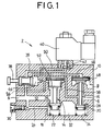
slow starting valve 2 as shown in FIG. 1 of the accompanying drawings. Theslow starting valve 2 comprises ablock 10 having an inlet port 4, anoutlet port 6, and adischarge port 8 which are defined therein, afirst valve body 14 disposed in apassage 12 which provides communication between the inlet port 4 and theoutlet port 6, and asecond valve body 16 disposed in thebody 10. - The
first valve body 14 has a smaller-diameterlower valve member 18 for closing thepassage 12. Thesecond valve body 16 has avalve member 20 for preventing communication between achamber 32 in theblock 10 and thedischarge port 8. Thevalve members respective springs valve members respective valve seats - A
needle valve 30 is disposed in theblock 10 below the inlet port 4. Theneedle valve 30 has a pointed distal end facing apassage 34 communicating with thechamber 32 that is defined between the first andsecond valve bodies passage 36 is defined in theblock 10 and extends from the inlet port 4 across a manuallymovable spool valve 38 to avalve body 42 of a solenoid-operatedvalve 40. - The
spool valve 38 is housed in achamber 44 from which apassage 46 extends to avalve member 48 of thesecond valve body 16. Apassage 50 which also extends from thevalve chamber 44 goes to thevalve body 42 of the solenoid-operatedvalve 40. Thefirst valve body 14 also has a larger-diameter valve member 52 housed in a chamber that is vented to the atmosphere through a passage 54. Thevalve member 52 has a pressure-bearing surface communicating with theoutlet port 6 through apassage 56. - When the solenoid-operated
valve 40 is inactivated and thespool valve 38 is in the position shown in FIG. 1, a fluid under pressure introduced from the inlet port 4 flows through thepassage 34 across theneedle valve 30 into thechamber 32. Since thevalve members chamber 32 are seated on therespective valve seats outlet port 6. - When the solenoid-operated
valve 40 is actuated, thevalve body 42 is opened, allowing the fluid under pressure introduced from the inlet port 4 to flow through thepassage 36 across thespool valve 38 into thepassage 50, and then from thechamber 44 through thepassage 46, thereby displacing thevalve member 48 of thesecond valve body 16 downwardly in FIG. 1. As a result, thevalve member 20 of thesecond valve body 16 is unseated from thevalve seat 28, so that the fluid under pressure introduced from the inlet port 4 flows through thepassage 34 and thechamber 32 into theoutlet port 6, from which the fluid under pressure is gradually supplied to an actuator (not shown) connected to theoutlet port 6. - The pressure of the fluid that flows into the
outlet port 6 is applied through thepassage 56 to thevalve member 52 of thefirst valve body 14. In the case where thecoil spring 22 has a sufficiently large resilient force, the fluid pressure supplied via theneedle valve 30 and applied to thevalve member 18 and the resilient force of thecoil spring 22 are large enough to overcome the pressure from the larger-diameter valve member 52, and hence thefirst valve body 14 is not opened. Since the amount of the fluid flowing through theneedle valve 30 to theoutlet port 6 is very small, the amount of the fluid supplied to the actuator is also very small, making it possible to start the actuator gradually, i.e., slowly. - When the fluid pressure applied to the
valve member 52 is gradually increased, thefirst valve body 14 is lowered in FIG. 1 while overcoming the fluid pressure acting on thevalve member 18 and the resilient force of thecoil spring 22. The fluid under pressure introduced from the inlet port 4 is therefore supplied directly to theoutlet port 6. - When the fluid under pressure flows after the
first valve body 14 is displaced downwardly, an appreciable pressure drop is developed, lowering the fluid pressure in theoutlet port 6. As a result, the fluid pressure in thepassage 56 drops, and thefirst valve body 14 is displaced upwardly under the fluid pressure acting on thevalve member 18 and the resilient force of thecoil spring 22, blocking the fluid pressure from the inlet port 4. Consequently, thefirst valve body 14 is closed after only a large amount of fluid under pressure is consumed. The actuator still operates slowly, and the pressure drop may cause erroneous operation of the pilot-operated valve. - The above drawback may be eliminated by increasing the area of the pressure-bearing surface of the
valve member 52 of thevalve body 14. However, the increased area of the pressure-bearing surface of thevalve member 52 may cause thevalve body 14 to open too early, and the actuator which has been started slowly may tend to operate quickly before it reaches the stroke end. - With the above arrangement, unless the area of the pressure-bearing surface of the
valve member 52 is considerably increased, thevalve body 14 cannot be displaced downwardly against thevalve member 18 which is urged upwardly by the fluid pressure introduced from the inlet port 4 and the resilient force of thecoil spring 22 because the primary fluid pressure from the inlet port 4 is applied to the lower surface of the larger-diameter valve member 52 and the fluid pressure lower than the primary fluid pressure is applied to the upper pressure-bearing surface of thevalve member 52. Accordingly, the conventional slow starting valve shown in FIG. 1 is necessarily large in size. - The EP-A-0 097 246 discloses a valve-device for gradually putting under pressure pneumatic systems, in particular for starting up of presses, pneumatic actuators and pneumatic power-consuming machines in general. The device comprises a valve casing defining a passage for the fluid between an inlet port and an outlet port. A pneumatically operated pressure-reducing valve is arranged in the fluid passage and operates in order to reduce the pressure of the fluid fed in. When the system is started up the valve opens and makes it possible to feed the fluid at full pressure value as soon as the pressure of the fluid in the system reaches a predetermined value. With this valve device, however, erroneous operation of elements arranged downstream of the valve cannot be avoided as the fluid under pressure discharged from the outlet port cannot be restricted when the single valve is open.
- The FR-A-2 582 749 further discloses a starting valve for pneumatiques installations that also comprises a single valve body controlling the fluid flow from the inlet to the outlet port. The valve body comprises two piston-like end-sections of different surfaces.
- It is an object of the present invention to provide a slow starting valve which holds a valve body open through positive utilization of a static pressure developed by the flow of a fluid under pressure for avoiding erroneous operation without being affected by a secondary fluid pressure, is relatively small in size, and largely cuts down the amount of a fluid under pressure consumed for displacing the valve body.
- According to the present invention, there is provided a slow starting valve comprising the features of claim 1.
- The first pressure-bearing surface is substantially twice as wide as the second pressure-bearing surface.
- The slow starting valve further includes a resilient member acting on the second pressure-bearing surface for normally urging the second valve body in a direction to seat the first pressure-bearing surface.
- The slow starting valve further includes a check valve disposed upstream of the needle valve in the passage, the check valve being closable to supply the fluid under pressure from the inlet port to the needle valve when the slow starting valve starts to operate.
- The check valve is opened to exhaust the fluid under pressure from the outlet port in bypassing relationship to the needle valve when the first valve body blocks the passage between the inlet port and the outlet port and opens the passage between the outlet port and a discharge port.
- The first pressure-bearing surface of the second valve is hemispherical in shape.
- The above and other objects, features, and advantages of the present invention will become apparent from the following description when taken in conjunction with the accompanying drawings which illustrate preferred embodiments of the present invention by way of example.
-
- FIG. 1 is a vertical cross-sectional view of a conventional slow starting valve;
- FIG. 2 is a vertical cross-sectional view of a slow starting valve according to an embodiment of the present invention, the view being illustrative of the manner in which a fluid under pressure operates when a solenoidoperated valve is actuated;
- FIG. 3 is a view similar to FIG. 2, showing the manner in which a fluid under pressure operates when a second valve body is displaced;
- FIG. 4 is a vertical cross-sectional view of a slow starting valve according to another embodiment of the present invention; and
- FIG. 5 is a cross-sectional view taken along line V - V of FIG. 4.
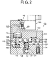
- FIGS. 2 and 3 schematically show a slow starting valve according to an embodiment of the present invention.
- The slow starting valve, generally designated by the
reference numeral 100, comprises ablock 102 having aninlet port 104, anoutlet port 106, adischarge port 108 defined therein. Theblock 102 also has achamber 110 defined therein near theinlet pot 104 and thedischarge port 108 with afirst valve body 112 disposed in thechamber 110. Thefirst valve body 112 has a larger-diameter valve member 114 on its upper end and a smaller-diameter valve member 116 on its lower end. Acoil spring 118 acts on thevalve member 116 for normally urging thefirst valve body 112 to move upwardly in FIGS. 2 and 3. - The
chamber 110 communicates with achamber 122 defined in theblock 100 through apassage 120, and thechamber 122 houses asecond valve body 124 therein. Thesecond valve body 124 has ahemispherical valve member 126 on its upper end and aslender passage 128 defined along the axis of thesecond valve body 124 and extending downwardly into thechamber 122. Thesecond valve body 124 is normally urged to move upwardly by acoil spring 130 disposed in thechamber 122. Thechamber 122 communicates through apassage 132 with theoutlet port 106. Aneedle valve 134 is disposed in theblock 102 and has an axis normal to the direction in which thepassage 132 extends. Theneedle valve 134 has a pointed distal end extending into aslender passage 136 defined in theblock 102. - A
check valve 138 is disposed in thepassage 120 and is normally urged by acoil spring 140 in a direction to prevent direct communication between thepassage 120 and thepassage 132. Theinlet port 104 communicates with apassage 142 defined in theblock 100, which can be closed by avalve body 146 of a solenoid-operatedvalve 144. Apassage 148 defined in theblock 100 opens toward thevalve body 146 and serves to apply a fluid pressure to thevalve member 114 of thefirst valve body 112. - The slow starting valve according to the above embodiment operates and offers advantages as follows:
- When the
valve body 146 of the solenoid-operatedvalve 144 closes thepassage 142, a fluid under pressure introduced from theinlet port 104 acts upwardly on thevalve member 116 of thefirst valve body 112. Under the fluid pressure thus applied to thevalve member 116 and also the resilient force of thecoil spring 118, thevalve member 116 is displaced upwardly and seated on avalve seat 115. Therefore, the fluid pressure is not supplied from theoutlet port 106 to an actuator (not shown) connected to theoutlet port 106. - When the solenoid-operated
valve 144 is actuated to unseat thevalve body 146 from its seat as shown in FIG. 2, the fluid pressure introduced from theinlet port 104 through thepassage 142 pushes and displaces thevalve member 114 of thefirst valve body 112 downwardly. Specifically, the fluid pressure applied to the pressure-bearing surface of thevalve member 114 which is larger than the pressure-bearing surface of thevalve member 116 is effective to lower thefirst valve body 112 against the bias of thecoil spring 118, as shown in FIG. 2. The fluid under pressure from theinlet port 104 now flows through thechamber 110 and thepassage 120 past thecheck valve 138 into thepassage 136. The fluid under pressure is restricted by theneedle valve 134 and then discharged from theoutlet port 106. The fluid under pressure discharged from theoutlet port 106 is supplied to the actuator to gradually drive the actuator. - Inasmuch as the fluid under pressure is restricted by the
needle valve 134, the fluid pressure in thepassages second valve body 124. Thehemispherical valve member 126 on the upper end of thesecond valve body 124 defines a semispherical pressure-bearing surface which is subjected to a fluid pressure buildup in thepassages second valve body 124 is displaced downwardly in its entirety. Specifically, as shown in FIG. 3, the fluid pressure buildup in thepassages hemispherical valve member 126 is large enough to overcome the bias of thecoil spring 130 and the pressure-bearing surface of the lower end of thesecond valve body 124, with the result that thesecond valve body 124 is lowered. At this time, the fluid under pressure from thepassage 120 is supplied through thepassage 132 and theoutlet port 106 to the actuator. Further, as readily understood be referring to Figures 2 and 3, when thefirst valve body 112 is raised to block flow between theinlet port 104 and thepassage 120, thedischarge port 108 is thereby put in communication with thepassage 120. Because thepassage 120 is opened to atmosphere via thedischarge port 108, the pressure in thepassage 132 becomes relatively larger than the pressure in thepassage 120. This pressure difference inpassages check valve 138 to open so as to allow any fluid under pressure in the region of theoutlet port 106 to be rapidly exhausted in bypassing relationship to theneedle valve 134. - The hemispherical pressure-bearing surface of the
valve body 126 is about twice as wide as the pressure-bearing surface of the lower end of thesecond valve body 124, and the primary fluid pressure is supplied to the lower end of thesecond valve body 124 through thepassage 128. Consequently, when the fluid pressure acting on thevalve body 126 overcomes the bias of thecoil spring 130 due to the difference between the areas of the pressurebearing surfaces of thevalve body 126 and the lower end of thesecond valve body 124, thesecond valve body 124 is displaced downwardly. Thepassages - FIGS. 4 and 5 show a slow starting valve according to another embodiment of the present invention. Those parts shown in FIGS. 4 and 5 which are identical to those shown in FIGS. 2 and 3 are denoted by identical reference numerals, and will not be described in detail below.
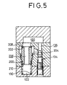
- The slow starting valve shown in FIGS. 4 and 5 has a
valve body 200 corresponding to thesecond valve body 124 shown in FIGS. 2 and 3. Thevalve body 200 has a pressure-bearingsurface 202 on its upper end, a pressure-bearingflange 204 on its central portion, and a pressure-bearingsurface 210 on its lower end. Thevalve body 200 has apassage 206 defined therein along its axis. Thevalve body 200 is normally urged to seat on anupper valve seat 208 under the bias of acoil spring 130. The upper pressure-bearingsurface 202 and the lower pressure-bearingsurface 210 have respective areas at a ratio of 2 : 1. The pressure-bearingflange 204 is twice as wide as the lower pressure-bearingsurface 210. Therefore, as the fluid pressure in thechamber 110 and thepassage 120 is increased by being restricted by theneedle valve 134, the fluid pressure acting on the pressure-bearingsurface 202 lowers thevalve body 200 at a certain time. Once the pressure-bearingsurface 202 is unseated off thevalve seat 208, thepassage 120 is brought into communication with thepassage 132, with the result that the fluid pressure also acts on theflange 204. Therefore, the fluid pressure applied to the pressure-bearingsurface 202 and the pressure-bearingflange 204 quickly displaces thevalve body 200 downwardly, allowing the fluid under pressure to flow from thepassages outlet port 106. - When the solenoid-operated
valve 144 is inactivated, thevalve body 146 closes thepassage 142. As a consequence, since no fluid pressure is applied to thevalve body 114, thevalve body 112 moves upwardly under the bias of thecoil spring 118 and fluid pressure acting upwardly to thesecond valve body 116 until thesecond valve body 116 is seated whereupon thesecond valve body 116 cuts off the communication between theinlet port 104 and thechamber 110. As a result, the pressure of the fluid gradually flowing via theneedle valve 134 into theoutlet port 106 is reduced on the pressure-bearingsurface 202, which moves upwardly and is finally seated on thevalve seat 208 under the bias of thecoil spring 130 and the fluid pressure acting on the pressure-bearingsurface 210. Therefore, the direct communication between thepassages - With the present invention, the actuator can gradually be started by the slow starting valve which is of a highly simple structure. The actuator is reliably prevented from operating erroneously, operates safely, and is not abruptly displaced when returned to the original position upon removal of the fluid pressure. The slow starting valve may be relatively small in size, and consumes a minimum amount of fluid under pressure.
- Although certain preferred embodiments of the present invention have been shown and described in detail, it should be understood that various changes and modifications may be made therein without departing from the scope of the appended claims.
Claims (6)
- A slow starting valve comprising:a valve block (102);said valve block (102) having an inlet port (104) defined therein for introducing a fluid under pressure, an outlet port (106) defined therein for discharging a fluid under pressure, and a passage (120) providing communication between said inlet and outlet ports;a first valve body (112) disposed in said passage (120) for selectively opening and closing said passage, said first valve body cooperating with a first valve seat (115) provided in said valve block;a second valve body (124) disposed downstream of said first valve body (112) with respect to a fluid flow through said passage (120) for selectively opening and closing said passage (120); anda needle valve (134) disposed in said passage;characterized in that:said needle valve (134) is disposed adjacent said outlet port (106) for restricting the fluid under pressure discharged from said outlet port (106) when said first valve body (112) is in an opened state and while the second valve body (124) is in a closed state; andsaid second valve body (124) having a passage (128) defined therein and communicating from one end to the other end thereof, and first and second pressure-bearing surfaces on said one and other ends, respectively, said first pressure-bearing surface (126) cooperating with a second valve seat provided in said valve block(102), said second valve body (124) being actuated by said upstream pressure of the fluid acting on both said first and second pressure-bearing surfaces, wherein said first pressure-bearing surface (126) is wider than said second pressure-bearing surface, and said second valve body (124) being opened by achievement of a predetermined value of upstream fluid pressure to allow said fluid to flow through an auxiliary passage (132) bypassing said needle valve (134).
- A slow starting valve according to claim 1, wherein said first pressure-bearing surface (126) is substantially twice as wide as said second pressure-bearing surface.
- A slow starting valve according to claim 2, further including a resilient member (130) acting on said second pressure-bearing surface for normally urging said second valve body (124) in a direction to seat said first pressure-bearing surface (126).
- A slow starting valve according to claim 1, further including a check valve (138) disposed upstream of said needle valve (134) in said passage (120), said check valve (138) being closable to supply the fluid under pressure from said inlet port (104) to said needle valve (134) when the slow starting valve starts to operate.
- A slow starting valve according to claim 4, wherein said check valve (138) is opened to exhaust the fluid under pressure from said outlet port (106) in bypassing relationship to said needle valve (134) when said first valve body (112) blocks the passage between the inlet port (104) and the outlet port (106) and opens the passage between the outlet port (106) and a discharge port (108).
- A slow starting valve according to claim 2, wherein said first pressure-bearing surface (126) of the second valve is hemispherical in shape.
Applications Claiming Priority (2)
| Application Number | Priority Date | Filing Date | Title |
|---|---|---|---|
| JP76582/91 | 1991-04-09 | ||
| JP3076582A JPH086727B2 (en) | 1991-04-09 | 1991-04-09 | Slow start valve |
Publications (2)
| Publication Number | Publication Date |
|---|---|
| EP0508271A1 EP0508271A1 (en) | 1992-10-14 |
| EP0508271B1 true EP0508271B1 (en) | 1996-05-29 |
Family
ID=13609279
Family Applications (1)
| Application Number | Title | Priority Date | Filing Date |
|---|---|---|---|
| EP92105495A Expired - Lifetime EP0508271B1 (en) | 1991-04-09 | 1992-03-31 | Slow starting valve |
Country Status (5)
| Country | Link |
|---|---|
| US (1) | US5381828A (en) |
| EP (1) | EP0508271B1 (en) |
| JP (1) | JPH086727B2 (en) |
| DE (1) | DE69211049T2 (en) |
| ES (1) | ES2088514T3 (en) |
Families Citing this family (9)
| Publication number | Priority date | Publication date | Assignee | Title |
|---|---|---|---|---|
| ITMI20032562A1 (en) * | 2003-12-22 | 2005-06-23 | Metal Work Spa | PROGRESSIVE STARTING GROUP FOR PNEUMATIC SYSTEMS |
| ITMI20032563A1 (en) * | 2003-12-22 | 2005-06-23 | Metal Work Spa | INTEGRATED AIR TREATMENT GROUP IN PNEUMATIC SYSTEMS |
| DE202004015468U1 (en) * | 2004-10-06 | 2005-01-05 | Festo Ag & Co.Kg | Soft start device for compressed air systems |
| DE502006008678D1 (en) * | 2006-12-05 | 2011-02-17 | Festo Ag & Co Kg | Soft start valve device |
| CA2715222C (en) * | 2008-02-15 | 2014-09-30 | Festo Ag & Co. Kg | Soft start device for pneumatic systems and method for the operation of a soft start device |
| US9360025B2 (en) * | 2010-07-22 | 2016-06-07 | Maradyne Corporation | Hydraulic soft start system |
| US8578713B2 (en) * | 2010-07-22 | 2013-11-12 | Maradyne Corporation | Hydraulic soft start system |
| US9239065B2 (en) * | 2010-07-22 | 2016-01-19 | Maradyne Corporation | Hydraulic soft start system |
| JP6061227B2 (en) * | 2011-11-02 | 2017-01-18 | Smc株式会社 | Flow control device |
Family Cites Families (4)
| Publication number | Priority date | Publication date | Assignee | Title |
|---|---|---|---|---|
| USRE30403E (en) * | 1974-05-31 | 1980-09-16 | Ross Operating Valve Company | Safety valve for fluid systems |
| US4596271A (en) * | 1980-10-02 | 1986-06-24 | Brundage Robert W | Fluid pressure device |
| IT1151291B (en) * | 1982-06-07 | 1986-12-17 | Univer Srl | VALVE DEVICE FOR GRADUAL PRESSURE OF PNEUMATIC SYSTEMS |
| FR2582749B1 (en) * | 1985-05-31 | 1989-09-01 | Levenez Yves | STARTER-CONNECTION FOR THE PROGRESSIVE PRESSURE OF PNEUMATIC INSTALLATIONS |
-
1991
- 1991-04-09 JP JP3076582A patent/JPH086727B2/en not_active Expired - Lifetime
-
1992
- 1992-03-31 US US07/861,381 patent/US5381828A/en not_active Expired - Lifetime
- 1992-03-31 EP EP92105495A patent/EP0508271B1/en not_active Expired - Lifetime
- 1992-03-31 ES ES92105495T patent/ES2088514T3/en not_active Expired - Lifetime
- 1992-03-31 DE DE69211049T patent/DE69211049T2/en not_active Expired - Lifetime
Also Published As
| Publication number | Publication date |
|---|---|
| US5381828A (en) | 1995-01-17 |
| JPH086727B2 (en) | 1996-01-29 |
| JPH04312205A (en) | 1992-11-04 |
| EP0508271A1 (en) | 1992-10-14 |
| DE69211049T2 (en) | 1996-12-19 |
| DE69211049D1 (en) | 1996-07-04 |
| ES2088514T3 (en) | 1996-08-16 |
Similar Documents
| Publication | Publication Date | Title |
|---|---|---|
| CA1122880A (en) | Hydraulic control valve unit | |
| EP0508271B1 (en) | Slow starting valve | |
| EP0353635B1 (en) | Fluid pressure controller for antilock brake control device | |
| EP0468621B1 (en) | Pilot valve for control valves and method of operation | |
| JPS6041268B2 (en) | valve | |
| US4088151A (en) | Cylinder locking apparatus | |
| JPS6255252A (en) | Control valve | |
| US4576416A (en) | Multi-circuit pressure medium brake system | |
| EP0559903A4 (en) | Valve device | |
| EP0819795A4 (en) | Hydraulic circuit for hydraulic machine | |
| JPS62101984A (en) | Pilot valve for two-step fluid mechanism and control method thereof | |
| EP0480965B1 (en) | Solenoid valve | |
| EP0473537B1 (en) | Dual independent input hydraulic shutoff | |
| US4396215A (en) | Log grapple device | |
| EP0638730A1 (en) | Control means for a hydraulic motor | |
| US4733691A (en) | Solenoid valve | |
| US3845508A (en) | Water closet control system | |
| JPH0740085Y2 (en) | Pilot check valve with slow return function | |
| WO1992016400A1 (en) | Method and apparatus for controlling pressure level in a compressed air adaptive braking system | |
| JPS5962783A (en) | Unloader valve | |
| EP1069323B1 (en) | Cross flow with crossmirror and lock out capability valve | |
| US3937524A (en) | Pneumatic braking systems for vehicles | |
| JP3712312B2 (en) | Hydraulic control device | |
| JPS6256525B2 (en) | ||
| JPS6238585B2 (en) |
Legal Events
| Date | Code | Title | Description |
|---|---|---|---|
| PUAI | Public reference made under article 153(3) epc to a published international application that has entered the european phase |
Free format text: ORIGINAL CODE: 0009012 |
|
| 17P | Request for examination filed |
Effective date: 19920410 |
|
| AK | Designated contracting states |
Kind code of ref document: A1 Designated state(s): CH DE ES FR GB IT LI SE |
|
| 17Q | First examination report despatched |
Effective date: 19940504 |
|
| GRAH | Despatch of communication of intention to grant a patent |
Free format text: ORIGINAL CODE: EPIDOS IGRA |
|
| GRAA | (expected) grant |
Free format text: ORIGINAL CODE: 0009210 |
|
| AK | Designated contracting states |
Kind code of ref document: B1 Designated state(s): CH DE ES FR GB IT LI SE |
|
| REF | Corresponds to: |
Ref document number: 69211049 Country of ref document: DE Date of ref document: 19960704 |
|
| REG | Reference to a national code |
Ref country code: ES Ref legal event code: BA2A Ref document number: 2088514 Country of ref document: ES Kind code of ref document: T3 |
|
| REG | Reference to a national code |
Ref country code: ES Ref legal event code: FG2A Ref document number: 2088514 Country of ref document: ES Kind code of ref document: T3 |
|
| ITF | It: translation for a ep patent filed | ||
| ET | Fr: translation filed | ||
| PLBE | No opposition filed within time limit |
Free format text: ORIGINAL CODE: 0009261 |
|
| STAA | Information on the status of an ep patent application or granted ep patent |
Free format text: STATUS: NO OPPOSITION FILED WITHIN TIME LIMIT |
|
| 26N | No opposition filed | ||
| REG | Reference to a national code |
Ref country code: GB Ref legal event code: IF02 |
|
| PGFP | Annual fee paid to national office [announced via postgrant information from national office to epo] |
Ref country code: FR Payment date: 20110404 Year of fee payment: 20 Ref country code: SE Payment date: 20110314 Year of fee payment: 20 Ref country code: CH Payment date: 20110324 Year of fee payment: 20 |
|
| PGFP | Annual fee paid to national office [announced via postgrant information from national office to epo] |
Ref country code: ES Payment date: 20110325 Year of fee payment: 20 Ref country code: DE Payment date: 20110325 Year of fee payment: 20 Ref country code: GB Payment date: 20110321 Year of fee payment: 20 |
|
| PGFP | Annual fee paid to national office [announced via postgrant information from national office to epo] |
Ref country code: IT Payment date: 20110329 Year of fee payment: 20 |
|
| REG | Reference to a national code |
Ref country code: DE Ref legal event code: R071 Ref document number: 69211049 Country of ref document: DE |
|
| REG | Reference to a national code |
Ref country code: DE Ref legal event code: R071 Ref document number: 69211049 Country of ref document: DE |
|
| REG | Reference to a national code |
Ref country code: CH Ref legal event code: PL |
|
| REG | Reference to a national code |
Ref country code: GB Ref legal event code: PE20 Expiry date: 20120330 |
|
| PG25 | Lapsed in a contracting state [announced via postgrant information from national office to epo] |
Ref country code: GB Free format text: LAPSE BECAUSE OF EXPIRATION OF PROTECTION Effective date: 20120330 |
|
| REG | Reference to a national code |
Ref country code: SE Ref legal event code: EUG |
|
| REG | Reference to a national code |
Ref country code: ES Ref legal event code: FD2A Effective date: 20120717 |
|
| PG25 | Lapsed in a contracting state [announced via postgrant information from national office to epo] |
Ref country code: ES Free format text: LAPSE BECAUSE OF EXPIRATION OF PROTECTION Effective date: 20120401 Ref country code: DE Free format text: LAPSE BECAUSE OF EXPIRATION OF PROTECTION Effective date: 20120401 |