EP0508253A1 - Procédé et dispositif de traitement thermique d'une bande continue munie d'une composition fluide ou pâteuse - Google Patents
Procédé et dispositif de traitement thermique d'une bande continue munie d'une composition fluide ou pâteuse Download PDFInfo
- Publication number
- EP0508253A1 EP0508253A1 EP92105433A EP92105433A EP0508253A1 EP 0508253 A1 EP0508253 A1 EP 0508253A1 EP 92105433 A EP92105433 A EP 92105433A EP 92105433 A EP92105433 A EP 92105433A EP 0508253 A1 EP0508253 A1 EP 0508253A1
- Authority
- EP
- European Patent Office
- Prior art keywords
- web
- treatment chamber
- air
- radiant
- heat
- Prior art date
- Legal status (The legal status is an assumption and is not a legal conclusion. Google has not performed a legal analysis and makes no representation as to the accuracy of the status listed.)
- Withdrawn
Links
- 238000010438 heat treatment Methods 0.000 title claims abstract description 16
- 238000000034 method Methods 0.000 title claims description 22
- 239000000203 mixture Substances 0.000 title description 3
- 239000012530 fluid Substances 0.000 title 1
- 229920005989 resin Polymers 0.000 claims abstract description 9
- 239000011347 resin Substances 0.000 claims abstract description 9
- 238000007664 blowing Methods 0.000 claims abstract description 5
- 239000000463 material Substances 0.000 claims description 24
- 230000005855 radiation Effects 0.000 claims description 12
- 239000004744 fabric Substances 0.000 claims description 6
- 239000007788 liquid Substances 0.000 claims description 5
- 238000002360 preparation method Methods 0.000 claims description 5
- 235000011837 pasties Nutrition 0.000 claims description 2
- 230000001105 regulatory effect Effects 0.000 claims description 2
- 229920003002 synthetic resin Polymers 0.000 claims description 2
- 239000000057 synthetic resin Substances 0.000 claims description 2
- 230000032258 transport Effects 0.000 abstract description 11
- 239000002904 solvent Substances 0.000 abstract description 6
- 239000000047 product Substances 0.000 description 11
- 238000009826 distribution Methods 0.000 description 6
- 238000004519 manufacturing process Methods 0.000 description 6
- 238000006243 chemical reaction Methods 0.000 description 4
- 229910052751 metal Inorganic materials 0.000 description 3
- 239000002184 metal Substances 0.000 description 3
- 229920000877 Melamine resin Polymers 0.000 description 2
- 230000000694 effects Effects 0.000 description 2
- 238000005265 energy consumption Methods 0.000 description 2
- 238000005338 heat storage Methods 0.000 description 2
- 239000002985 plastic film Substances 0.000 description 2
- 229920006255 plastic film Polymers 0.000 description 2
- KXGFMDJXCMQABM-UHFFFAOYSA-N 2-methoxy-6-methylphenol Chemical compound [CH]OC1=CC=CC([CH])=C1O KXGFMDJXCMQABM-UHFFFAOYSA-N 0.000 description 1
- 239000004593 Epoxy Substances 0.000 description 1
- ISWSIDIOOBJBQZ-UHFFFAOYSA-N Phenol Chemical compound OC1=CC=CC=C1 ISWSIDIOOBJBQZ-UHFFFAOYSA-N 0.000 description 1
- 229910000831 Steel Inorganic materials 0.000 description 1
- 229910052782 aluminium Inorganic materials 0.000 description 1
- XAGFODPZIPBFFR-UHFFFAOYSA-N aluminium Chemical compound [Al] XAGFODPZIPBFFR-UHFFFAOYSA-N 0.000 description 1
- 239000012876 carrier material Substances 0.000 description 1
- 239000006185 dispersion Substances 0.000 description 1
- 230000008020 evaporation Effects 0.000 description 1
- 238000001704 evaporation Methods 0.000 description 1
- 238000007667 floating Methods 0.000 description 1
- -1 flooring Substances 0.000 description 1
- 238000009408 flooring Methods 0.000 description 1
- 238000005470 impregnation Methods 0.000 description 1
- 239000002649 leather substitute Substances 0.000 description 1
- 239000004745 nonwoven fabric Substances 0.000 description 1
- 229920001568 phenolic resin Polymers 0.000 description 1
- 239000005011 phenolic resin Substances 0.000 description 1
- 229920000058 polyacrylate Polymers 0.000 description 1
- 229920000647 polyepoxide Polymers 0.000 description 1
- 229920002635 polyurethane Polymers 0.000 description 1
- 239000004814 polyurethane Substances 0.000 description 1
- 229920000915 polyvinyl chloride Polymers 0.000 description 1
- 239000004800 polyvinyl chloride Substances 0.000 description 1
- 238000009420 retrofitting Methods 0.000 description 1
- 239000011265 semifinished product Substances 0.000 description 1
- 239000010959 steel Substances 0.000 description 1
- 239000000725 suspension Substances 0.000 description 1
- XLYOFNOQVPJJNP-UHFFFAOYSA-N water Substances O XLYOFNOQVPJJNP-UHFFFAOYSA-N 0.000 description 1
- 239000002759 woven fabric Substances 0.000 description 1
Images
Classifications
-
- F—MECHANICAL ENGINEERING; LIGHTING; HEATING; WEAPONS; BLASTING
- F26—DRYING
- F26B—DRYING SOLID MATERIALS OR OBJECTS BY REMOVING LIQUID THEREFROM
- F26B3/00—Drying solid materials or objects by processes involving the application of heat
- F26B3/28—Drying solid materials or objects by processes involving the application of heat by radiation, e.g. from the sun
- F26B3/283—Drying solid materials or objects by processes involving the application of heat by radiation, e.g. from the sun in combination with convection
-
- B—PERFORMING OPERATIONS; TRANSPORTING
- B29—WORKING OF PLASTICS; WORKING OF SUBSTANCES IN A PLASTIC STATE IN GENERAL
- B29C—SHAPING OR JOINING OF PLASTICS; SHAPING OF MATERIAL IN A PLASTIC STATE, NOT OTHERWISE PROVIDED FOR; AFTER-TREATMENT OF THE SHAPED PRODUCTS, e.g. REPAIRING
- B29C35/00—Heating, cooling or curing, e.g. crosslinking or vulcanising; Apparatus therefor
- B29C35/02—Heating or curing, e.g. crosslinking or vulcanizing during moulding, e.g. in a mould
- B29C35/04—Heating or curing, e.g. crosslinking or vulcanizing during moulding, e.g. in a mould using liquids, gas or steam
- B29C35/06—Heating or curing, e.g. crosslinking or vulcanizing during moulding, e.g. in a mould using liquids, gas or steam for articles of indefinite length
-
- B—PERFORMING OPERATIONS; TRANSPORTING
- B29—WORKING OF PLASTICS; WORKING OF SUBSTANCES IN A PLASTIC STATE IN GENERAL
- B29C—SHAPING OR JOINING OF PLASTICS; SHAPING OF MATERIAL IN A PLASTIC STATE, NOT OTHERWISE PROVIDED FOR; AFTER-TREATMENT OF THE SHAPED PRODUCTS, e.g. REPAIRING
- B29C35/00—Heating, cooling or curing, e.g. crosslinking or vulcanising; Apparatus therefor
- B29C35/02—Heating or curing, e.g. crosslinking or vulcanizing during moulding, e.g. in a mould
- B29C35/08—Heating or curing, e.g. crosslinking or vulcanizing during moulding, e.g. in a mould by wave energy or particle radiation
- B29C35/10—Heating or curing, e.g. crosslinking or vulcanizing during moulding, e.g. in a mould by wave energy or particle radiation for articles of indefinite length
-
- F—MECHANICAL ENGINEERING; LIGHTING; HEATING; WEAPONS; BLASTING
- F26—DRYING
- F26B—DRYING SOLID MATERIALS OR OBJECTS BY REMOVING LIQUID THEREFROM
- F26B13/00—Machines and apparatus for drying fabrics, fibres, yarns, or other materials in long lengths, with progressive movement
- F26B13/10—Arrangements for feeding, heating or supporting materials; Controlling movement, tension or position of materials
- F26B13/101—Supporting materials without tension, e.g. on or between foraminous belts
- F26B13/104—Supporting materials without tension, e.g. on or between foraminous belts supported by fluid jets only; Fluid blowing arrangements for flotation dryers, e.g. coanda nozzles
Definitions
- the invention relates to a method for the heat treatment of a web of material provided with a liquid or pasty preparation and a device for carrying out such a method according to the preamble of claim 1 or claim 12.
- Such a method and such a device are known from GB-PS 12 34 956.
- a material web provided with a liquid preparation is treated in a treatment chamber by means of heat radiation and warm air.
- the treatment chamber is arranged vertically.
- the web runs in the form of an inverted U through the treatment chamber.
- the treatment air is led in counterflow to the web. It is blown in at the lower end of the treatment chamber.
- a large number of heating pipes through which hot steam flows are attached to the treatment chamber on both sides of the web.
- the warm air serves to evaporate the solvent and to transport it away.
- the warm air does not work by directly blowing on the web, which is more effective, but creates difficulties with regard to achieving an optimally uniform temperature distribution over the surface of the web.
- a uniform temperature distribution is crucial, for example, for the curing of an appropriately treated web.
- a vertical material guide through a treatment chamber is also known from JP-PS 56-36352.
- the treatment chamber On the opposite side of the web, the treatment chamber only contains air nozzle outlets on the side of a line carrying warm air. This device also has the disadvantage that the uniformity of the temperature distribution does not meet high requirements.
- the invention was therefore based on the object to develop a method and to provide a corresponding device with which the disadvantages of the known devices can be eliminated and by treating a product web a product can be produced which meets the highest quality requirements, which is the case with the treatment an optimal uniformity of the temperature distribution and also a controllable temperature influence on the web is required. It was also given the task of producing a treatment chamber with the necessary facilities in terms of the manufacturing effort and also in terms of economical for the production of products that meet high quality requirements To be able to advantageously produce energy consumption in operation.
- the principle of the method and device according to the senses is that zones of exposure to warm air and zones of the effect of radiant heat on the goods alternate in succession in the vertical transport direction of the goods. Insufficiently uniform heat distribution in the warm air zones is corrected in the subsequent zones with radiation heat that acts uniformly over the entire width of the web.
- the warm air is blown from opposite sides in the transport direction against the goods spell in order to stabilize the goods spell according to the principle applied to the float dryer.
- These warm air zones are quasi non-contact guide means for a long web, which can also be guided through a relatively narrow space between oppositely arranged radiation heaters due to these guide means even with a long web length, so that due to these very closely opposed radiant heaters there is an intense heat effect and the energy consumption is kept correspondingly low can be.
- a prepreg is a sheet-like structure provided with a hardenable resin, on which the synthetic resin applied in the form of a solution or dispersion is hardened to a certain degree by a chemical reaction.
- the technical properties of a prepreg are determined by the state of hardening, so that the hardening reaction must be carried out very carefully and precisely to the desired degree of hardening. In particular, constant quality and thus a constant degree of hardening over the entire fabric is desired.
- the method according to the invention and the device can also be used for the heat treatment of other material webs which are to be treated on one or both sides.
- Nonwovens, woven fabrics, metal webs such as steel and aluminum, and high-temperature-resistant plastic films come into consideration as material webs.
- the materials or preparations applied to the web may be Trade acrylic polymers, polyvinyl chloride, polyurethane, melamine resins, etc.
- the product can then be a painted or printed metal sheet or plastic film, a decorative material, flooring, synthetic leather or refined paper.
- the invention is suitable both for the production of finished products and for the production of semi-finished products.
- An advantageous embodiment of the invention is characterized in that the web of material is first blown in the treatment chamber and then subjected to radiant heat.
- the goods are first exposed to radiant heat in the treatment chamber and then blown on.
- the material web in the treatment chamber is alternately blown with warm air and exposed to radiant heat.
- the goods can be blown alternately with warm air from both sides in the same blowing area.
- radiant heaters are provided on both sides of the web, it is therefore advantageous to design at least one of them to be removable. When the web is introduced, this radiant heater is moved away, so the distance between the two radiant heaters is increased so that the web can be inserted correctly. The distance is then reduced again during operation. When retrofitting an existing radiation dryer, it is time-consuming or difficult to attach a removable radiator. It is then advantageous to use only one radiant heater To be provided so that the problem described above does not occur at all when inserting the web.
- the material web is exposed to radiant heat from both sides at the same time.
- Radiant heaters are therefore provided on both sides of the product ban. At least one of these two radiant heaters can preferably be moved away. Radiation heating is doubled by the radiation on both sides, and the device is accordingly more effective.
- the web is heated over its width with radiant heat of different temperatures, preferably with radiant heat of three different temperatures.
- the radiant heaters thus have several, preferably three, zones transverse to the direction of movement of the material web, the temperature of which can be regulated independently of one another.
- the fact that the radiant heaters are divided into individual, individually controllable zones across the width of the treatment chamber, i.e. because the width of the radiant heaters applies different amounts of heat to the fabric, can make the hardening reaction and thus the degree of hardening more even.
- subdivision into three different temperature zones is sufficient up to a web width of 1.3 to 2.0 m. From a web width of 2.0 m, it can be advantageous to provide four or more temperature zones. The more temperature zones are provided, the better the heat supply can be controlled across the width of the web, but the more complex the arrangement becomes.
- the radiation temperature is higher than the air temperature, preferably at least 15 ° C.
- the radiant heater has a heat storage capacity. This cannot be achieved with pure electric radiators, but with heating plates, preferably made of metal, which have a heat storage capacity.
- the plates can, for example, have tubes on their side facing away from the goods ban, through which oil, water, steam or a similar liquid flows. It is also possible to heat the plates using electrical energy.
- An advantageous development of the device according to the invention is characterized in that the surface of the radiant heater facing the web is smooth.
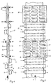
- nozzle box 5 In the treatment chamber 1, the walls 2 of which are only shown in FIG. 3, is on the inlet side (in FIGS. 1 and 2) a first group 3 of three nozzle boxes 4, 5, 6 of conventional design arranged in the transverse direction to the web 7.
- the inlet side of the first nozzle box 4 is in the drawing on the right of the web 7, the second nozzle box 5 in the direction of movement or transport T of the web offset to the left of the web 7 and the third nozzle box 6 in turn offset to the right of the web.
- Each nozzle box 5, 6, 7 has two slot nozzles 8, 9, which extend in the transverse direction of the product spell 7, through which a blow jet directed obliquely towards one another and against the product web emerges.
- the air warms the web, blows solvent out of the impregnation resin and transports the solvent away.
- the outflow direction of the air is illustrated with small arrows a.
- the first group 3 of nozzle boxes 4, 5, 6 is followed in the transport direction T of the web 7 by a radiant heater 11, 12 arranged on opposite sides of the web 7, each with a smooth, flat radiation heating surface 13, 14 facing the web 7.
- Each radiant heater 11 , 12 is divided transversely to the transport direction T into three individual heating zones 15, 16, 17 ( Figure 2).
- Each of these zones has its own heating coil 18, 19, 20 which is independent of the other, each with a heating medium inlet 21, 22, 23 and a heating medium outlet 24, 25, 26.
- This arrangement allows the web to be heated as required, varying across the width and thus optimizing the uniformity of the degree of hardening over its surface.
- the heating zones 16, 17, 18 shown have the same width.
- the radiant heaters 11, 12 can also be in zones of different widths, for example two wide outer zones and a narrow central zone or two narrow outer zones and a wide central zone.
- the radiant heaters can also be divided into only two or more than three independently controllable zones.
- the two radiation heaters 11, 12 are followed in the transport direction T by a further group 27 of three nozzle boxes in an arrangement similar to that in the first group 3, followed by two further radiant heaters 28, 29 arranged on both sides of the web 7.
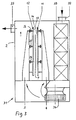
- the nozzle boxes 4, 5, 6 are preferably fed with a mixture of fresh air and circulating air.
- a corresponding device 31 is shown in FIG. 3.
- Fresh air is supplied to a circulating air fan 34 via a fresh air inlet 32 and filter 33 via a heat exchanger or a direct burner; mixed with circulating air and with the air mixture, the nozzle boxes 4, 5 and 6 are fed.
- the solvent-laden exhaust air from the interior of the treatment chamber 1 is led away through an air outlet 35.
- the fresh air can be preheated.
- a treatment chamber in a system according to the invention can be composed of several units of the type shown, from 2 to 6 m in length.
- the nozzle boxes and the heating plates can be arranged so as to be adjustable in their distance from the material web.
- the nozzle boxes can, as shown, be arranged in groups of three, in groups of two to six. It is also possible to arrange only a single nozzle box between two radiant heaters.
- the individual nozzle box can be arranged on one side of the web of radiant heaters on the same or on the opposite side of the radiators of the web.
- the method according to the invention is suitable for product spans made of paper, nonwoven or fabrics and for the known curable resin types such as. B. phenol, epoxy and melamine resins.
- the individual conditions required for the respective material type in the respective system depend on the carrier material of the goods spell, on the resin type, on the resin application and on the desired degree of hardening and are easily set by the expert after preliminary tests.
- the air temperature is advantageously 20 o to 25 o C below the temperature of the radiant heater.
Landscapes
- Engineering & Computer Science (AREA)
- Health & Medical Sciences (AREA)
- Mechanical Engineering (AREA)
- General Engineering & Computer Science (AREA)
- Physics & Mathematics (AREA)
- Oral & Maxillofacial Surgery (AREA)
- Thermal Sciences (AREA)
- Life Sciences & Earth Sciences (AREA)
- Microbiology (AREA)
- Toxicology (AREA)
- Textile Engineering (AREA)
- Treatment Of Fiber Materials (AREA)
- Drying Of Solid Materials (AREA)
- Yarns And Mechanical Finishing Of Yarns Or Ropes (AREA)
Applications Claiming Priority (2)
| Application Number | Priority Date | Filing Date | Title |
|---|---|---|---|
| CH1104/91 | 1991-04-12 | ||
| CH110491 | 1991-04-12 |
Publications (1)
| Publication Number | Publication Date |
|---|---|
| EP0508253A1 true EP0508253A1 (fr) | 1992-10-14 |
Family
ID=4202575
Family Applications (1)
| Application Number | Title | Priority Date | Filing Date |
|---|---|---|---|
| EP92105433A Withdrawn EP0508253A1 (fr) | 1991-04-12 | 1992-03-30 | Procédé et dispositif de traitement thermique d'une bande continue munie d'une composition fluide ou pâteuse |
Country Status (2)
| Country | Link |
|---|---|
| EP (1) | EP0508253A1 (fr) |
| JP (1) | JPH05148753A (fr) |
Citations (12)
| Publication number | Priority date | Publication date | Assignee | Title |
|---|---|---|---|---|
| US3793741A (en) * | 1972-01-07 | 1974-02-26 | Smitherm Industries | Drying apparatus with moisture profile control |
| US3924569A (en) * | 1974-08-28 | 1975-12-09 | Goodyear Tire & Rubber | Apparatus for treating tire cord fabric |
| GB2133526A (en) * | 1979-11-16 | 1984-07-25 | Thomas Marsden Smith | Infra-red heating |
| EP0157403A2 (fr) * | 1984-04-02 | 1985-10-09 | Limited Sinter | Procédé et dispositif pour sécher une bande imprégnée d'une résine synthétique durcissable |
| EP0235723A2 (fr) * | 1986-03-06 | 1987-09-09 | Contiweb B.V. Stork | Dispositif pour le guidage flottant de bandes de matière au moyen d'un gaz ou d'un liquide |
| DE8703671U1 (de) * | 1987-03-11 | 1988-07-14 | Diedrich Metallbau Inh. Udo Diedrich, 3000 Hannover | Vorrichtung zum Trocknen von auf einem bewegten Träger in Druckanlagen aufgebrachten nassen Farb- und/oder Lackfilmen auf Wasserbasis |
| EP0291832A1 (fr) * | 1987-05-16 | 1988-11-23 | Hilmar Vits | Dispositif de séchage de bandes de matière guidées librement par les tuyères d'un coussin d'air |
| WO1988009845A1 (fr) * | 1987-06-04 | 1988-12-15 | Valmet Paper Machinery Inc. | Procede de sechage d'une bande de papier ou similaire |
| WO1989004890A1 (fr) * | 1987-11-26 | 1989-06-01 | Valmet Oy | Procede et dispositif de sechage d'un bande de papier ou similaire lors de l'appret de sa surface par voie automatique |
| EP0346081A1 (fr) * | 1988-06-07 | 1989-12-13 | W.R. Grace & Co.-Conn. | Barre de support pneumatique |
| DE4029487A1 (de) * | 1989-09-25 | 1991-04-04 | Valmet Paper Machinery Inc | Verfahren und vorrichtung zum fuehren einer papierbahn in der streichmaschine |
| EP0452867A1 (fr) * | 1990-04-18 | 1991-10-23 | Van Brandwijk Systems Programming B.V. | Procédé et dispositif de traitement thermique d'une bande continue munie d'une composition fluide ou pâteuse |
-
1992
- 1992-03-30 EP EP92105433A patent/EP0508253A1/fr not_active Withdrawn
- 1992-04-13 JP JP11969392A patent/JPH05148753A/ja active Pending
Patent Citations (12)
| Publication number | Priority date | Publication date | Assignee | Title |
|---|---|---|---|---|
| US3793741A (en) * | 1972-01-07 | 1974-02-26 | Smitherm Industries | Drying apparatus with moisture profile control |
| US3924569A (en) * | 1974-08-28 | 1975-12-09 | Goodyear Tire & Rubber | Apparatus for treating tire cord fabric |
| GB2133526A (en) * | 1979-11-16 | 1984-07-25 | Thomas Marsden Smith | Infra-red heating |
| EP0157403A2 (fr) * | 1984-04-02 | 1985-10-09 | Limited Sinter | Procédé et dispositif pour sécher une bande imprégnée d'une résine synthétique durcissable |
| EP0235723A2 (fr) * | 1986-03-06 | 1987-09-09 | Contiweb B.V. Stork | Dispositif pour le guidage flottant de bandes de matière au moyen d'un gaz ou d'un liquide |
| DE8703671U1 (de) * | 1987-03-11 | 1988-07-14 | Diedrich Metallbau Inh. Udo Diedrich, 3000 Hannover | Vorrichtung zum Trocknen von auf einem bewegten Träger in Druckanlagen aufgebrachten nassen Farb- und/oder Lackfilmen auf Wasserbasis |
| EP0291832A1 (fr) * | 1987-05-16 | 1988-11-23 | Hilmar Vits | Dispositif de séchage de bandes de matière guidées librement par les tuyères d'un coussin d'air |
| WO1988009845A1 (fr) * | 1987-06-04 | 1988-12-15 | Valmet Paper Machinery Inc. | Procede de sechage d'une bande de papier ou similaire |
| WO1989004890A1 (fr) * | 1987-11-26 | 1989-06-01 | Valmet Oy | Procede et dispositif de sechage d'un bande de papier ou similaire lors de l'appret de sa surface par voie automatique |
| EP0346081A1 (fr) * | 1988-06-07 | 1989-12-13 | W.R. Grace & Co.-Conn. | Barre de support pneumatique |
| DE4029487A1 (de) * | 1989-09-25 | 1991-04-04 | Valmet Paper Machinery Inc | Verfahren und vorrichtung zum fuehren einer papierbahn in der streichmaschine |
| EP0452867A1 (fr) * | 1990-04-18 | 1991-10-23 | Van Brandwijk Systems Programming B.V. | Procédé et dispositif de traitement thermique d'une bande continue munie d'une composition fluide ou pâteuse |
Also Published As
| Publication number | Publication date |
|---|---|
| JPH05148753A (ja) | 1993-06-15 |
Similar Documents
| Publication | Publication Date | Title |
|---|---|---|
| EP0452867B1 (fr) | Procédé et dispositif de traitement thermique d'une bande continue munie d'une composition fluide ou pâteuse | |
| EP0448983B1 (fr) | Dispositif pour le soufflage des deux côtés d'un matériau en forme de bande | |
| EP0631098B1 (fr) | Sécheur en continu pour articles de forme plane, et installation de revêtement incorporant un tel sécheur | |
| DE3528365C2 (fr) | ||
| DE2902955C2 (de) | Durchbiegungseinstellwalze | |
| EP0708905A1 (fr) | Sechoir a air chaud pour secher des surfaces recouvertes d'un revetement | |
| DE19710549A1 (de) | Verfahren und Anlage zum Imprägnieren und Trocknen einer durchlaufenden Bahn | |
| DE102013004131B4 (de) | Vorrichtung zum Behandeln einer Beschichtung einer Fahrzeugkarosserie | |
| EP0157403B1 (fr) | Procédé et dispositif pour sécher une bande imprégnée d'une résine synthétique durcissable | |
| EP2225044B2 (fr) | Dispositif de refroidissement et procédé de refroidissement d'objets sortant d'un dispositif d'application de revêtement | |
| DE2320614B2 (de) | Fließbettreaktor | |
| DE102018002074A1 (de) | Trocknungsvorrichtung zum Trocknen von Gipsplatten | |
| EP2066456B2 (fr) | Procédé de revêtement en poudre de substrats en bois | |
| EP0508254A1 (fr) | Procédé et dispositif de traitement thermique d'une bande continue munie d'une composition fluide ou pâteuse | |
| EP3546382B1 (fr) | Barre diffusant de la vapeur et tunnel de rétraction | |
| DE69221740T2 (de) | Verfahren zum Trocknen von perforierten Ziegelsteinen und Vorrichtung zum Durchführen des Verfahrens. | |
| EP0508253A1 (fr) | Procédé et dispositif de traitement thermique d'une bande continue munie d'une composition fluide ou pâteuse | |
| DE102023112579A1 (de) | Vorrichtung und Verfahren zum Trocknen und/oder Temperieren eines flächigen Werkstückes | |
| EP3765807A1 (fr) | Procédé et dispositif destinés à sécher des plaques | |
| DE19750847C1 (de) | Verfahren zum Kühlen von heißverpressten Platten, insbesondere Holzspan- und Faserplatten und Kühlstrecke zur Verfahrensdurchführung | |
| EP3765806B1 (fr) | Boîte à buses pour un dispositif de séchage servant à sécher des matériaux en forme de panneau | |
| DE102018219289B3 (de) | Verfahren und Vorrichtung zur Beaufschlagung einer Materialbahn mit einem Gasstrom | |
| DE102005031444A1 (de) | Vorrichtung zum Befeuchten einer Materialbahn | |
| EP0063647A1 (fr) | Dispositif pour le séchage par air chaud de matières textiles | |
| EP0433228B1 (fr) | Procédé et appareil de lavage en continu d'une bande textile |
Legal Events
| Date | Code | Title | Description |
|---|---|---|---|
| PUAI | Public reference made under article 153(3) epc to a published international application that has entered the european phase |
Free format text: ORIGINAL CODE: 0009012 |
|
| AK | Designated contracting states |
Kind code of ref document: A1 Designated state(s): AT BE CH DE ES FR GB IT LI NL SE |
|
| 17P | Request for examination filed |
Effective date: 19930113 |
|
| 17Q | First examination report despatched |
Effective date: 19931111 |
|
| STAA | Information on the status of an ep patent application or granted ep patent |
Free format text: STATUS: THE APPLICATION IS DEEMED TO BE WITHDRAWN |
|
| 18D | Application deemed to be withdrawn |
Effective date: 19940322 |