EP0508167B1 - Air ring and method for controlling blown film thickness - Google Patents
Air ring and method for controlling blown film thickness Download PDFInfo
- Publication number
- EP0508167B1 EP0508167B1 EP92104638A EP92104638A EP0508167B1 EP 0508167 B1 EP0508167 B1 EP 0508167B1 EP 92104638 A EP92104638 A EP 92104638A EP 92104638 A EP92104638 A EP 92104638A EP 0508167 B1 EP0508167 B1 EP 0508167B1
- Authority
- EP
- European Patent Office
- Prior art keywords
- air
- air ring
- temperature
- thickness
- film
- Prior art date
- Legal status (The legal status is an assumption and is not a legal conclusion. Google has not performed a legal analysis and makes no representation as to the accuracy of the status listed.)
- Expired - Lifetime
Links
- 238000000034 method Methods 0.000 title claims abstract description 22
- 238000001816 cooling Methods 0.000 claims abstract description 43
- 230000004044 response Effects 0.000 claims abstract description 9
- 230000008569 process Effects 0.000 claims abstract description 6
- 239000002985 plastic film Substances 0.000 claims abstract description 5
- 229920006255 plastic film Polymers 0.000 claims abstract description 5
- 238000005192 partition Methods 0.000 claims description 11
- 238000005259 measurement Methods 0.000 claims description 10
- 239000011347 resin Substances 0.000 claims description 5
- 229920005989 resin Polymers 0.000 claims description 5
- 230000009977 dual effect Effects 0.000 claims description 4
- 239000003000 extruded plastic Substances 0.000 claims description 4
- 230000004075 alteration Effects 0.000 claims description 3
- 238000007599 discharging Methods 0.000 claims description 3
- 238000010438 heat treatment Methods 0.000 claims description 3
- 238000012986 modification Methods 0.000 description 16
- 230000004048 modification Effects 0.000 description 16
- 238000012937 correction Methods 0.000 description 10
- 238000004519 manufacturing process Methods 0.000 description 7
- 238000001125 extrusion Methods 0.000 description 6
- 238000012546 transfer Methods 0.000 description 6
- 238000009434 installation Methods 0.000 description 4
- 229920000642 polymer Polymers 0.000 description 4
- 230000000694 effects Effects 0.000 description 3
- 238000012545 processing Methods 0.000 description 3
- 238000013459 approach Methods 0.000 description 2
- 230000009467 reduction Effects 0.000 description 2
- 238000004804 winding Methods 0.000 description 2
- 238000010521 absorption reaction Methods 0.000 description 1
- 230000003749 cleanliness Effects 0.000 description 1
- 239000012141 concentrate Substances 0.000 description 1
- 238000013461 design Methods 0.000 description 1
- 230000001627 detrimental effect Effects 0.000 description 1
- 238000010586 diagram Methods 0.000 description 1
- 230000007613 environmental effect Effects 0.000 description 1
- 238000010096 film blowing Methods 0.000 description 1
- 239000012530 fluid Substances 0.000 description 1
- 229920001903 high density polyethylene Polymers 0.000 description 1
- 239000004700 high-density polyethylene Substances 0.000 description 1
- 230000006872 improvement Effects 0.000 description 1
- 230000001939 inductive effect Effects 0.000 description 1
- 229920000092 linear low density polyethylene Polymers 0.000 description 1
- 239000004707 linear low-density polyethylene Substances 0.000 description 1
- 229920001684 low density polyethylene Polymers 0.000 description 1
- 239000004702 low-density polyethylene Substances 0.000 description 1
- 238000012423 maintenance Methods 0.000 description 1
- 230000007246 mechanism Effects 0.000 description 1
- 239000000203 mixture Substances 0.000 description 1
- 239000008188 pellet Substances 0.000 description 1
- 230000000737 periodic effect Effects 0.000 description 1
- 229920003023 plastic Polymers 0.000 description 1
- 239000004033 plastic Substances 0.000 description 1
- 238000003303 reheating Methods 0.000 description 1
- 230000000153 supplemental effect Effects 0.000 description 1
Images


Classifications
-
- B—PERFORMING OPERATIONS; TRANSPORTING
- B29—WORKING OF PLASTICS; WORKING OF SUBSTANCES IN A PLASTIC STATE IN GENERAL
- B29C—SHAPING OR JOINING OF PLASTICS; SHAPING OF MATERIAL IN A PLASTIC STATE, NOT OTHERWISE PROVIDED FOR; AFTER-TREATMENT OF THE SHAPED PRODUCTS, e.g. REPAIRING
- B29C48/00—Extrusion moulding, i.e. expressing the moulding material through a die or nozzle which imparts the desired form; Apparatus therefor
- B29C48/25—Component parts, details or accessories; Auxiliary operations
- B29C48/88—Thermal treatment of the stream of extruded material, e.g. cooling
- B29C48/885—External treatment, e.g. by using air rings for cooling tubular films
-
- B—PERFORMING OPERATIONS; TRANSPORTING
- B29—WORKING OF PLASTICS; WORKING OF SUBSTANCES IN A PLASTIC STATE IN GENERAL
- B29C—SHAPING OR JOINING OF PLASTICS; SHAPING OF MATERIAL IN A PLASTIC STATE, NOT OTHERWISE PROVIDED FOR; AFTER-TREATMENT OF THE SHAPED PRODUCTS, e.g. REPAIRING
- B29C48/00—Extrusion moulding, i.e. expressing the moulding material through a die or nozzle which imparts the desired form; Apparatus therefor
- B29C48/03—Extrusion moulding, i.e. expressing the moulding material through a die or nozzle which imparts the desired form; Apparatus therefor characterised by the shape of the extruded material at extrusion
- B29C48/09—Articles with cross-sections having partially or fully enclosed cavities, e.g. pipes or channels
- B29C48/10—Articles with cross-sections having partially or fully enclosed cavities, e.g. pipes or channels flexible, e.g. blown foils
-
- B—PERFORMING OPERATIONS; TRANSPORTING
- B29—WORKING OF PLASTICS; WORKING OF SUBSTANCES IN A PLASTIC STATE IN GENERAL
- B29C—SHAPING OR JOINING OF PLASTICS; SHAPING OF MATERIAL IN A PLASTIC STATE, NOT OTHERWISE PROVIDED FOR; AFTER-TREATMENT OF THE SHAPED PRODUCTS, e.g. REPAIRING
- B29C48/00—Extrusion moulding, i.e. expressing the moulding material through a die or nozzle which imparts the desired form; Apparatus therefor
- B29C48/25—Component parts, details or accessories; Auxiliary operations
- B29C48/88—Thermal treatment of the stream of extruded material, e.g. cooling
- B29C48/911—Cooling
- B29C48/9115—Cooling of hollow articles
- B29C48/912—Cooling of hollow articles of tubular films
-
- B—PERFORMING OPERATIONS; TRANSPORTING
- B29—WORKING OF PLASTICS; WORKING OF SUBSTANCES IN A PLASTIC STATE IN GENERAL
- B29C—SHAPING OR JOINING OF PLASTICS; SHAPING OF MATERIAL IN A PLASTIC STATE, NOT OTHERWISE PROVIDED FOR; AFTER-TREATMENT OF THE SHAPED PRODUCTS, e.g. REPAIRING
- B29C48/00—Extrusion moulding, i.e. expressing the moulding material through a die or nozzle which imparts the desired form; Apparatus therefor
- B29C48/25—Component parts, details or accessories; Auxiliary operations
- B29C48/92—Measuring, controlling or regulating
-
- B—PERFORMING OPERATIONS; TRANSPORTING
- B29—WORKING OF PLASTICS; WORKING OF SUBSTANCES IN A PLASTIC STATE IN GENERAL
- B29C—SHAPING OR JOINING OF PLASTICS; SHAPING OF MATERIAL IN A PLASTIC STATE, NOT OTHERWISE PROVIDED FOR; AFTER-TREATMENT OF THE SHAPED PRODUCTS, e.g. REPAIRING
- B29C2948/00—Indexing scheme relating to extrusion moulding
- B29C2948/92—Measuring, controlling or regulating
- B29C2948/92009—Measured parameter
- B29C2948/92114—Dimensions
- B29C2948/92152—Thickness
-
- B—PERFORMING OPERATIONS; TRANSPORTING
- B29—WORKING OF PLASTICS; WORKING OF SUBSTANCES IN A PLASTIC STATE IN GENERAL
- B29C—SHAPING OR JOINING OF PLASTICS; SHAPING OF MATERIAL IN A PLASTIC STATE, NOT OTHERWISE PROVIDED FOR; AFTER-TREATMENT OF THE SHAPED PRODUCTS, e.g. REPAIRING
- B29C2948/00—Indexing scheme relating to extrusion moulding
- B29C2948/92—Measuring, controlling or regulating
- B29C2948/92323—Location or phase of measurement
- B29C2948/92438—Conveying, transporting or storage of articles
-
- B—PERFORMING OPERATIONS; TRANSPORTING
- B29—WORKING OF PLASTICS; WORKING OF SUBSTANCES IN A PLASTIC STATE IN GENERAL
- B29C—SHAPING OR JOINING OF PLASTICS; SHAPING OF MATERIAL IN A PLASTIC STATE, NOT OTHERWISE PROVIDED FOR; AFTER-TREATMENT OF THE SHAPED PRODUCTS, e.g. REPAIRING
- B29C2948/00—Indexing scheme relating to extrusion moulding
- B29C2948/92—Measuring, controlling or regulating
- B29C2948/92504—Controlled parameter
- B29C2948/92609—Dimensions
- B29C2948/92647—Thickness
-
- B—PERFORMING OPERATIONS; TRANSPORTING
- B29—WORKING OF PLASTICS; WORKING OF SUBSTANCES IN A PLASTIC STATE IN GENERAL
- B29C—SHAPING OR JOINING OF PLASTICS; SHAPING OF MATERIAL IN A PLASTIC STATE, NOT OTHERWISE PROVIDED FOR; AFTER-TREATMENT OF THE SHAPED PRODUCTS, e.g. REPAIRING
- B29C2948/00—Indexing scheme relating to extrusion moulding
- B29C2948/92—Measuring, controlling or regulating
- B29C2948/92504—Controlled parameter
- B29C2948/92704—Temperature
-
- B—PERFORMING OPERATIONS; TRANSPORTING
- B29—WORKING OF PLASTICS; WORKING OF SUBSTANCES IN A PLASTIC STATE IN GENERAL
- B29C—SHAPING OR JOINING OF PLASTICS; SHAPING OF MATERIAL IN A PLASTIC STATE, NOT OTHERWISE PROVIDED FOR; AFTER-TREATMENT OF THE SHAPED PRODUCTS, e.g. REPAIRING
- B29C2948/00—Indexing scheme relating to extrusion moulding
- B29C2948/92—Measuring, controlling or regulating
- B29C2948/92819—Location or phase of control
- B29C2948/92923—Calibration, after-treatment or cooling zone
Definitions
- This invention comprises apparatus and method for controlling gauge uniformity in the manufacture of blown plastic film.
- Uniformity of the nozzle gap, distribution of the air from the cooling ring, uniformity of temperature and attendant viscosity of the molten polymer, cleanliness and maintenance of the equipment and environmental factor in the building in which the equipment is located have all been recognized as influencing the uniformity of the gauge of the finished blown film.
- EP-A- 325 961 A2 blown film thickness control by means of infrared heaters arranged about the bubble circumference downstream of the die and air ring has been shown.
- infrared heaters whose wavelengths must be matched to the absorption characteristics of the film being processed, are used to heat locally thick areas, thereby reducing the resistance to deformation, with the net result that the thickness uniformity following transverse expansion is improved.
- Use of heaters in the flat die area in cases of biaxial orientation involving reheating followed by machine direction and transverse deformation are generally known, as described in U.S. Patent no. 3,782,873.
- U.S. Patent no. 4,209,475 describes an apparatus and method for controlling film thickness that is unique to blown film processing. As previously indicated, in the blown film process it is customary to apply one or more streams of cooling air to the extruded tube following extrusion. In the last mentioned patent an air ring is described that is equipped with a large number of independently adjustable blades that can project into the discharged cooling air stream. These deflector blades, by locally inducing more or less local turbulence into the cooling air stream, will offset cooling of the extruded tube along longitudinal bands.
- Document DE-A-26 58 518 discloses a film blowing apparatus including a supplemental air ring consisting of correcting nozzles which are separately controlled by allocated throttle valves. Accordingly, a feedback control is rendered possible.
- the servo mechanism disclosed therein does primarily vary the volume of air dispensed by each individual nozzle.
- an air cooling ring conventionally used to apply one or more cooling air streams to the outside surface of a freshly extruded plastic tube is modified to include one or more cooling air temperature modification devices, said temperature modification devices arranged about the internal air flow paths of the air ring to locally modify the temperature of the cooling air applied to the extruded tube.
- These local variations in cooling air temperature result in local variations in bubble cooling rate and consequent variation in temperature, viscosity and draw down rate during transverse bubble expansion, with higher temperature thick areas undergoing relatively greater transverse stretching and consequent thinning than cooler areas.
- Modification to the cooling air temperature is made in response to online post expansion film thickness measurements corrected, if applicable, for any rotation of the film tube between the die and the measuring head, said temperature modification preferably adjusted periodically in response to periodic film thickness measurements.
- the method is applicable to both external and internal bubble cooling systems or combination of both, and to temperature modification that consist of local elevation of temperature, local reduction of temperatures, a combination of both local elevation and reduction relative to the mean cooling air temperature.
- the local temperature variation will be temperature increase, with such temperature increase applied to thick portion of the film to reduced such thick region, and the temperature modifying means will comprise heater installed into the air ring.
- the temperature modifying means will comprise heater installed into the air ring.
- the circumferential extent over which each individual heater will be active will be determined by turbulence and mixing within the air ring.
- Radially oriented flow straighteners i.e. partitions in the flow path, can be used between adjacent heaters or a series of heaters to concentrate the effect and limit the circumferential extent of the effect of a single heater or a group of heaters.
- the air rings can be of any number of flow paths, although single flow air rings are currently preferred for high stalk extrusion processes, while double flow air rings are preferred for all others.
- temperature modifying devices preferably will be placed in the flow path for the major cooling flow.
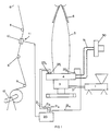
- Figure 1 is an elevation of a typical blown film machinery installation including an air ring and control means according to the present invention.
- Figure 2 is a radial cross section through a single flow air ring according to the present invention.
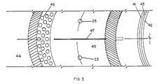
- Figure 3 is a section along A-A of Figure 2 showing the orientation of the internal deflectors and temperature altering means.
- Figure 4 is a radial cross section through a dual flow air ring.
- Figure 5 is a representative profile of film thickness prior to any correction
- Figure 6 is a representative profile of film thickness and correction signal for the same condition as Figure 6.
- FIG. 1 For an overall description of a blown film manufacturing installation.
- resin pellets are fed into the inlet of extruder 1, where, under the influence of heat and mechanical working, they will be melted.
- the melted plastic passes through adapter 2 to annular die 3, where it is extruded through an annular nozzle to form tubular web 5.
- the tube is inflated with air to produce an inflated tube diameter significantly greater than the diameter of the annular nozzle. This diameter increase is referred to as transverse expansion or transverse drawdown.
- the tube is extended upwardly toward nip rolls 7, which are used to define the upper closed end of the bubble and to draw the extruded web 5 from the die to thereby axially thin the web and to introduce machine direction orientation.
- collapsing devices 6 e.g. plates, slats, or a series of rollers, beneath nip roll pair 7, that are used to flatten the bubble from its round shape at the die to that of double layer flat sheet at the nip roll pair.
- a roll winding device 12 From the nip roll pair the now flattened web is brought to a roll winding device 12 over a series of idler rollers 8.
- a roll winding device 12 it is customary in the production of blown film to rotate either the die, the die and extruder, or the collapser and nip roll, so as to distribute gauge variations over the width of the roll being wound on winding device 12.
- any such device that rotates a minimum of ⁇ 180 degrees from its zero position, i.e. at least 360 degrees in total
- a thickness gauge of any conventional type, e.g. infrared or nuclear positioned at the web edge and measuring through two thicknesses of films, will provide an accurate profile of gauge variations across the web.
- the measuring gauge As the die, etc. is rotating and the measuring gauge is both stationary and a significant distance from the die, helical twist in the bubble must be accounted for in assigning a measured thickness to a specific position at the air ring.
- Thickness measurements from gauge 10 are transmitted over circuit 11 to processor 20. Also transmitted to processor 20 is a rotation signal that is used by the processor for identifying a reference position. Processor 20 takes the thickness data from gauge 10 and internally generates a circumferential thickness profile for web 5 which is then compared to a desired profile. In response to deviations from the desired thickness profile, processor 20 will calculate an appropriate correction signal or signals assigned to a particular circumferential position on air ring 4, and transmit that signal to the appropriate temperature modification device 25.
- FIG. 2 shows a single flow air ring according to the present invention.
- a single flow air ring of the type shown in this Figure 2 would be used in a high stalk extrusion process, typically one for processing high density polyethylene resin.
- Air from blower 50 flows through air supply hose 51 (not shown in Figure 2) through air ring inlet port 40 into inlet plenum 44. From the inlet plenum 44 air will pass through transfer ports 46 into outlet plenum 45. Transfer ports 46 serve to alter the tangentially oriented incoming flow direction in outer plenum 44 into an essentially radially oriented flow in outlet flow path 45. Air flow continues essentially radially, until discharged essentially parallel to web 5 through annular gap 43 found between air ring outer lip 41 and inner lip 42.
- temperature control element 25 Inserted into outlet flow path 45 is temperature control element 25.
- temperature modification device 25 could be a mixing nozzle supplied with intensely chilled air or heated air, so that the temperature of the discharged air could be either lowered or raised, or an externally heated device
- the currently preferred temperature modification device 25 is an electrical cartridge heater.
- Temperature modification device 25 can be inserted into outlet flow path 45 through an opening in the air ring structure, and held in position and sealed against air leakage by use of a tube fitting 26. Provision should be made in the design of device 25 so that the portion of device 25 held within fitting 26 is not heated.
- electrical cartridge heaters having an output of approximately 100 watts per 25,4 mm (per inch) of active length at 240 volts have proved satisfactory as the temperature modification device.
- tangential air flow in inlet plenum 44 is converted to essentially radial air flow by transfer ports 46.
- partitions 47 may be located between each adjacent element 25, or may be located between element 25 periodically, e.g. one partition every three temperature modifying devices.
- Partition 47 extends radially inwardly to approach annular gap 43.
- the purpose in extending this partition to approach annular gap 43 is to minimize the distance over which mixing of air flows from adjacent cells may occur.
- a dual flow air ring suitable for blown film extrusion of low density polyethylene resin, linear low density polyethylene resin, and blends thereof and containing temperature modification devices 25' is shown in Figure 4.
- this air ring is identical in structure to that shown in Figure 2.
- Transfer port 46b passes air from inlet plenum 44 to lower gap outlet flow path 45b, while transfer ports 46a pass air from inlet plenum 44 to upper gap outlet flow path 45a.
- the bulk of the cooling air is discharged from the upper gap, so that temperature modification devices 25' are located in the upper gap outlet plenum 45a.
- Partitions 47' are placed between adjacent control elements 25' to minimize the circumferential extent of any cooling air temperature corrections.
- the number of temperature modifying devices 25 used in a particular air ring will depend on numerous factors including air ring size, capacity of the individual temperature modifying devices 25, and the capacity of the processor. For instance, 60 individual temperature modifying devices, each individually controlled by processor 20 are preferred for an air ring used in conjunction with a 22,86 cm (9") diameter die. Four temperature modifying devices 25, each serving a quarter of this circumference, would seem to be the smallest practical number of elements from which effective control could be expected.
- a film bubble 5 is formed by extrusion through annular die 3. Cooling air is applied to the external surface of bubble 5 through air cooling ring 4. Bubble 5 is collapsed and pulled away from die 3 by nip rolls 7 and collapsing roll 6. The now flattened tube is lead over a series of idler rolls 8 to a winder 12. Interspersed along the path of travel is film thickness gauge 10, which will periodically be used to measure film gauge along the full circumference of the flattened film.
- Output from film thickness gauge 10 will be transmitted along conduit 11 to processor 20.
- processor 20 appropriate corrections are made to the thickness signals from thickness gauge 10 to correct for rotation of bubble 5 between air ring 4 and thickness gauge 10, so that all thickness measurements are related back to a particular air ring 4 location.
- a corrective signal is then sent to the appropriate temperature modifying device 25 or devices along conduit 21, locally altering the temperature of the discharged cooling air. Local alteration of the discharged cooling air results in local variation in cooling rate of web 5. These variations in cooling rate result in non-uniform transverse drawdown, i.e. thinning, of web 5.
- temperature modifying devices 25 are heaters, locally warmed air would be applied to thicker than desired areas, resulting in slower cooling of the thick areas during transverse expansion and greater thinning relative to more rapidly cooled areas. If the local temperature modifications were a cooling, the cooler air would be applied to the areas to reduce the extent of thinning during transverse drawdown. Thickness measurements are made regularly, and new correction signals are made based on these measurements. These new correction signals are in turn applied to temperature modifying device 25, and the measuring/correcting cycle continues on an iteritive basis.
- the circumferential gauge distribution may appear as shown in the upper portion of Figure 5.
- the numbers along the horizontal axis of the figure represent the individual temperature correcting elements, while the solid line indicates film thickness at the location indicated. It should be noted that, as shown in Figure 5, the air ring is equipped with 60 individual correction elements. Further, the film over elements 1 to 30 was generally thin, while the film was generally thick over elements 31 to 60.
Landscapes
- Engineering & Computer Science (AREA)
- Mechanical Engineering (AREA)
- Physics & Mathematics (AREA)
- Thermal Sciences (AREA)
- Shaping By String And By Release Of Stress In Plastics And The Like (AREA)
- Extrusion Moulding Of Plastics Or The Like (AREA)
- Manufacture Of Motors, Generators (AREA)
Abstract
Description
- This invention comprises apparatus and method for controlling gauge uniformity in the manufacture of blown plastic film.
- Production of blown plastic film by the processes of extruding molten polymer through an annular die nozzle, surrounding the extruded tube by an air cooling ring, cooling the extruded tube by discharging air from the air cooling ring onto the surface of the extruded tube, holding the extruded polymer tube closed between opposed nip rolls, inflating the closed tube between the annular die nozzle and the nip rolls to a diameter greater than that of the annular die, and drawing the polymer tube from the nozzle with the nip rolls at a rate greater than the linear rate of discharge from the annular die nozzle is well known. Uniformity of the nozzle gap, distribution of the air from the cooling ring, uniformity of temperature and attendant viscosity of the molten polymer, cleanliness and maintenance of the equipment and environmental factor in the building in which the equipment is located have all been recognized as influencing the uniformity of the gauge of the finished blown film. In view of the detrimental effects of gauge non-uniformity to subsequent processing wound rolls of blown film, it is customary to rotate portions of the equipment, e.g. extruder, die, nip rolls and collapser, to effect a distribution of gauge non-uniformity across the roll face.
- While the previously mentioned factors have long been recognized to lead to gauge non-uniformities in the finished film, numerous schemes have been proposed to deliberately adjust some of these same factors to compensate for the gauge non-uniformities or to produce a desired thickness profile. In the flat die area, both local mechanical adjustments of the die opening in response to a thickness measurement signal, U.S. Patent nos. 3,122,782 and 3,122,783 and direct local heating of selected portions of the die responsible for greater thickness U.S. patent No. 3,161,711 are known.
- A series of U.S. patents 4,246,212; 4,339,403; 4,339,404; 4,351,785; 4,425,290; 4,464,318 extend the basic methods of mechanical deformation and/or temperature variation of the die lips to annular blown film dies. In U.S. Patent no. 4,246,212 the outer nozzle ring of the annular die has been subdivided into a number of temperature control sectors which can be separately supplied with heated or cooled fluids to locally affect melt viscosity and the resulting film thickness.
- In U.S. patent No. 4,339,403 the correcting sections of the nozzle ring, either mechanical or thermal, are influenced in response to the circumferential lengths of film sectors of constant cross sectional area, until such circumferential lengths are equal. The remaining patents in this series deal with methods for determining and implementing correction commands.
- In EP-A- 325 961 A2 blown film thickness control by means of infrared heaters arranged about the bubble circumference downstream of the die and air ring has been shown. In this method, infrared heaters, whose wavelengths must be matched to the absorption characteristics of the film being processed, are used to heat locally thick areas, thereby reducing the resistance to deformation, with the net result that the thickness uniformity following transverse expansion is improved. Use of heaters in the flat die area in cases of biaxial orientation involving reheating followed by machine direction and transverse deformation are generally known, as described in U.S. Patent no. 3,782,873.
- While the previously mentioned patents all describe variation in techniques previously used in flat die extrusion applications, U.S. Patent no. 4,209,475 describes an apparatus and method for controlling film thickness that is unique to blown film processing. As previously indicated, in the blown film process it is customary to apply one or more streams of cooling air to the extruded tube following extrusion. In the last mentioned patent an air ring is described that is equipped with a large number of independently adjustable blades that can project into the discharged cooling air stream. These deflector blades, by locally inducing more or less local turbulence into the cooling air stream, will offset cooling of the extruded tube along longitudinal bands. By selectively altering the cooling rates along the longitudinal bands in response to gauge variation in the expanded film, these variations can be reduced, i.e. slower cooling of thick bands relative to adjacent thin ones results in proportionally more deformation during transverse tube expansion and consequent variation or difference in film gauge. Although this patent primarily dealt with manual actuation of the deflector blades, mention was made of a system utilizing motorized adjustment of individual blades in response to control signals from an online thickness measuring device.
- The method and apparatus of the present invention are defined by the independent patent claims.
- The combination of features set forth in the preamble of
patent claim 1 and 10, respectively, is known from US-A-4,606,879. - Document DE-A-26 58 518 discloses a film blowing apparatus including a supplemental air ring consisting of correcting nozzles which are separately controlled by allocated throttle valves. Accordingly, a feedback control is rendered possible. The servo mechanism disclosed therein does primarily vary the volume of air dispensed by each individual nozzle.
- A new and improved method and apparatus for automatic control of thickness variations in blown film production operations have been developed which are readily and relatively inexpensively adaptable to existing as well as new blown film manufacturing installations. In accordance with this improvement an air cooling ring conventionally used to apply one or more cooling air streams to the outside surface of a freshly extruded plastic tube is modified to include one or more cooling air temperature modification devices, said temperature modification devices arranged about the internal air flow paths of the air ring to locally modify the temperature of the cooling air applied to the extruded tube. These local variations in cooling air temperature result in local variations in bubble cooling rate and consequent variation in temperature, viscosity and draw down rate during transverse bubble expansion, with higher temperature thick areas undergoing relatively greater transverse stretching and consequent thinning than cooler areas. Modification to the cooling air temperature is made in response to online post expansion film thickness measurements corrected, if applicable, for any rotation of the film tube between the die and the measuring head, said temperature modification preferably adjusted periodically in response to periodic film thickness measurements.
- The method is applicable to both external and internal bubble cooling systems or combination of both, and to temperature modification that consist of local elevation of temperature, local reduction of temperatures, a combination of both local elevation and reduction relative to the mean cooling air temperature.
- In the preferred embodiment of the invention, the local temperature variation will be temperature increase, with such temperature increase applied to thick portion of the film to reduced such thick region, and the temperature modifying means will comprise heater installed into the air ring. When heaters are used, a relatively large number of control zones can be established, the circumferential extent over which each individual heater will be active will be determined by turbulence and mixing within the air ring. Radially oriented flow straighteners, i.e. partitions in the flow path, can be used between adjacent heaters or a series of heaters to concentrate the effect and limit the circumferential extent of the effect of a single heater or a group of heaters. The air rings can be of any number of flow paths, although single flow air rings are currently preferred for high stalk extrusion processes, while double flow air rings are preferred for all others. In the case of double flow air rings, temperature modifying devices preferably will be placed in the flow path for the major cooling flow.
- Figure 1 is an elevation of a typical blown film machinery installation including an air ring and control means according to the present invention.
- Figure 2 is a radial cross section through a single flow air ring according to the present invention.
- Figure 3 is a section along A-A of Figure 2 showing the orientation of the internal deflectors and temperature altering means.
- Figure 4 is a radial cross section through a dual flow air ring.
- Figure 5 is a representative profile of film thickness prior to any correction, and
- Figure 6 is a representative profile of film thickness and correction signal for the same condition as Figure 6.
- Reference is now made to Figure 1 for an overall description of a blown film manufacturing installation. In such an installation, resin pellets are fed into the inlet of extruder 1, where, under the influence of heat and mechanical working, they will be melted. From extruder 1 the melted plastic passes through adapter 2 to annular
die 3, where it is extruded through an annular nozzle to formtubular web 5. Adjacent to die 3 there is anair cooling ring 4, that is used to apply cooling and gauge control air to the exterior surface of the extruded tube. The tube is inflated with air to produce an inflated tube diameter significantly greater than the diameter of the annular nozzle. This diameter increase is referred to as transverse expansion or transverse drawdown. The tube is extended upwardly toward nip rolls 7, which are used to define the upper closed end of the bubble and to draw theextruded web 5 from the die to thereby axially thin the web and to introduce machine direction orientation. - There are a series of collapsing
devices 6, e.g. plates, slats, or a series of rollers, beneath nip roll pair 7, that are used to flatten the bubble from its round shape at the die to that of double layer flat sheet at the nip roll pair. - From the nip roll pair the now flattened web is brought to a
roll winding device 12 over a series ofidler rollers 8. As will be well known to those skilled in the art, it is customary in the production of blown film to rotate either the die, the die and extruder, or the collapser and nip roll, so as to distribute gauge variations over the width of the roll being wound onwinding device 12. So long as any such device is used that rotates a minimum of ±180 degrees from its zero position, i.e. at least 360 degrees in total, a thickness gauge of any conventional type, e.g. infrared or nuclear, positioned at the web edge and measuring through two thicknesses of films, will provide an accurate profile of gauge variations across the web. As the die, etc. is rotating and the measuring gauge is both stationary and a significant distance from the die, helical twist in the bubble must be accounted for in assigning a measured thickness to a specific position at the air ring. - Thickness measurements from
gauge 10 are transmitted over circuit 11 toprocessor 20. Also transmitted toprocessor 20 is a rotation signal that is used by the processor for identifying a reference position.Processor 20 takes the thickness data fromgauge 10 and internally generates a circumferential thickness profile forweb 5 which is then compared to a desired profile. In response to deviations from the desired thickness profile,processor 20 will calculate an appropriate correction signal or signals assigned to a particular circumferential position onair ring 4, and transmit that signal to the appropriatetemperature modification device 25. - Figure 2 shows a single flow air ring according to the present invention. A single flow air ring of the type shown in this Figure 2 would be used in a high stalk extrusion process, typically one for processing high density polyethylene resin. Air from blower 50 (not shown in Figure 2) flows through air supply hose 51 (not shown in Figure 2) through air
ring inlet port 40 intoinlet plenum 44. From theinlet plenum 44 air will pass throughtransfer ports 46 intooutlet plenum 45.Transfer ports 46 serve to alter the tangentially oriented incoming flow direction inouter plenum 44 into an essentially radially oriented flow inoutlet flow path 45. Air flow continues essentially radially, until discharged essentially parallel toweb 5 throughannular gap 43 found between air ringouter lip 41 andinner lip 42. - Inserted into
outlet flow path 45 istemperature control element 25. Althoughtemperature modification device 25 could be a mixing nozzle supplied with intensely chilled air or heated air, so that the temperature of the discharged air could be either lowered or raised, or an externally heated device, the currently preferredtemperature modification device 25 is an electrical cartridge heater.Temperature modification device 25 can be inserted intooutlet flow path 45 through an opening in the air ring structure, and held in position and sealed against air leakage by use of atube fitting 26. Provision should be made in the design ofdevice 25 so that the portion ofdevice 25 held within fitting 26 is not heated. Generally, electrical cartridge heaters having an output of approximately 100 watts per 25,4 mm (per inch) of active length at 240 volts have proved satisfactory as the temperature modification device. - As previously indicated, tangential air flow in
inlet plenum 44 is converted to essentially radial air flow bytransfer ports 46. However, it has been found desirable to include radially orientedpartitions 47 betweenadjacent devices 25 to reduce the circumferential extent of the temperature modified cooling air stream. The partitions may be located between eachadjacent element 25, or may be located betweenelement 25 periodically, e.g. one partition every three temperature modifying devices. - The orientation of
partition 47 relative to the die lip and adjacenttemperature modification devices 25 is shown in Figure 3.Partition 47 extends radially inwardly to approachannular gap 43. The purpose in extending this partition to approachannular gap 43 is to minimize the distance over which mixing of air flows from adjacent cells may occur. - A dual flow air ring suitable for blown film extrusion of low density polyethylene resin, linear low density polyethylene resin, and blends thereof and containing temperature modification devices 25' is shown in Figure 4. Up to transfer ports 46a and 46b, this air ring is identical in structure to that shown in Figure 2. Transfer port 46b passes air from
inlet plenum 44 to lower gap outlet flow path 45b, while transfer ports 46a pass air frominlet plenum 44 to upper gap outlet flow path 45a. As is customary with dual flow air rings, the bulk of the cooling air is discharged from the upper gap, so that temperature modification devices 25' are located in the upper gap outlet plenum 45a. Partitions 47' are placed between adjacent control elements 25' to minimize the circumferential extent of any cooling air temperature corrections. - The number of
temperature modifying devices 25 used in a particular air ring will depend on numerous factors including air ring size, capacity of the individualtemperature modifying devices 25, and the capacity of the processor. For instance, 60 individual temperature modifying devices, each individually controlled byprocessor 20 are preferred for an air ring used in conjunction with a 22,86 cm (9") diameter die. Fourtemperature modifying devices 25, each serving a quarter of this circumference, would seem to be the smallest practical number of elements from which effective control could be expected. - In blown film production the apparatus of the present invention will be used as follows: A
film bubble 5 is formed by extrusion throughannular die 3. Cooling air is applied to the external surface ofbubble 5 throughair cooling ring 4.Bubble 5 is collapsed and pulled away fromdie 3 by nip rolls 7 and collapsingroll 6. The now flattened tube is lead over a series of idler rolls 8 to awinder 12. Interspersed along the path of travel isfilm thickness gauge 10, which will periodically be used to measure film gauge along the full circumference of the flattened film. - Output from
film thickness gauge 10 will be transmitted along conduit 11 toprocessor 20. Atprocessor 20 appropriate corrections are made to the thickness signals fromthickness gauge 10 to correct for rotation ofbubble 5 betweenair ring 4 andthickness gauge 10, so that all thickness measurements are related back to aparticular air ring 4 location. A corrective signal is then sent to the appropriatetemperature modifying device 25 or devices alongconduit 21, locally altering the temperature of the discharged cooling air. Local alteration of the discharged cooling air results in local variation in cooling rate ofweb 5. These variations in cooling rate result in non-uniform transverse drawdown, i.e. thinning, ofweb 5. Whentemperature modifying devices 25 are heaters, locally warmed air would be applied to thicker than desired areas, resulting in slower cooling of the thick areas during transverse expansion and greater thinning relative to more rapidly cooled areas. If the local temperature modifications were a cooling, the cooler air would be applied to the areas to reduce the extent of thinning during transverse drawdown. Thickness measurements are made regularly, and new correction signals are made based on these measurements. These new correction signals are in turn applied totemperature modifying device 25, and the measuring/correcting cycle continues on an iteritive basis. - Following startup of a blown film line but prior to any attempts at gauge correction, the circumferential gauge distribution may appear as shown in the upper portion of Figure 5. In Figure 5 the numbers along the horizontal axis of the figure represent the individual temperature correcting elements, while the solid line indicates film thickness at the location indicated. It should be noted that, as shown in Figure 5, the air ring is equipped with 60 individual correction elements. Further, the film over elements 1 to 30 was generally thin, while the film was generally thick over elements 31 to 60.
- The gauge control system was then turned on, and after approximately 30 minutes, the results shown in Figure 6 were obtained. In Figure 6 the upper graph again represents a trace of film gauge versus circumferential position at the air ring, while the lower plot represents the percentage of power applied to each control element. Comparison of Figure 5 with the upper portion of Figure 6 shows the magnitude of the gauge variation has been substantially, i.e. greater than 50%, reduced. The lower part of Figure 7, i.e. the bar diagram, shows the percentage of available heating power applied to each correcting element.
- The foregoing description has described the preferred embodiment of the present invention and has described its method of operation. Variations and modifications may be made without departing from the principle of the invention. It is intended that all variation and modification fall within the scope of the following claims.
Claims (12)
- An air ring (4) for controlling gauge of blown plastic film comprising:(a) a generally annular plenum (44),(b) an annular orifice (43) for discharging cooling air against an extruded plastic tube passing through the air ring,(c) a flow path (45) for cooling air between said plenum and said annular orifice,(d) means for controlling the temperature of said cooling air, characterized in that said means include a plurality of temperature modifying devices (25) inserted in said path between said plenum and orifice whereby the temperature of cooling air discharged against said extruded plastic tube can be locally varied.
- An air ring according to claim 1 wherein said temperature modifying devices are electrical cartridge heaters (25).
- An air ring according to claim 1 or 2 further comprising a radially oriented partition (47) located in the flow path between any two temperature modifying devices.
- An air ring according to claim 3 wherein said partitions (47) are located in a regular sequence with respect to the modifying devices.
- An air ring according to claim 2 wherein the number of electrical cartridge heaters is 4 or greater.
- An air ring according to claim 5 wherein the number of electrical cartridge heaters is at least 60.
- An air ring according to claim 6 wherein the number of partitions equals the number of electrical cartridge heaters.
- A system for producing blown film including an extruder, an annular die, an air ring as defined in one of claims 1 to 7 for discharging cooling air on an extruded plastic tube, a thickness measurement system, and a nip roll assembly, wherein said temperature modifying devices are controlled in response to said thickness measurements, whereby the thickness of the resulting film can be locally altered.
- The system of claim 8 wherein said air ring is a dual flow air ring and said temperature modifying devices act upon the larger volumetric flow.
- A method for controlling the thickness of plastic film produced by the blown film process comprising:a) extruding a molten tube of resin from an annular die,b) applying a stream of cooling air to the outside of the extruded tube from an air ring that surrounds the extruded tube,c) expanding the diameter of the extruded tube and drawing it axially away from the die to bring the film to final width and thickness,d) measuring the thickness of the film following expansion and draw down,e) comparing the thickness distribution of the expanded and drawn down film to the desired thickness profile,f) relating the film thickness measurements to the locations of the annular air ring through which the film had passed, characterized in that the temperature of the air discharged from the air ring adjacent to the areas of non-desired thickness is locally altered whereby the magnitude of the non-desired thicknesses is reduced.
- A method according to claim 10 wherein said areas of non-desired thickness are relatively thick areas and the local alteration of temperature is a heating.
- A method to claim 10 or 11 wherein said areas of non-desired thickness are relatively thin areas and the local alteration of temperature is a cooling.
Applications Claiming Priority (2)
| Application Number | Priority Date | Filing Date | Title |
|---|---|---|---|
| US07/674,589 US5288219A (en) | 1991-03-25 | 1991-03-25 | Air ring for controlling blown film thickness |
| US674589 | 1991-03-25 |
Publications (3)
| Publication Number | Publication Date |
|---|---|
| EP0508167A2 EP0508167A2 (en) | 1992-10-14 |
| EP0508167A3 EP0508167A3 (en) | 1993-02-10 |
| EP0508167B1 true EP0508167B1 (en) | 1995-03-08 |
Family
ID=24707192
Family Applications (1)
| Application Number | Title | Priority Date | Filing Date |
|---|---|---|---|
| EP92104638A Expired - Lifetime EP0508167B1 (en) | 1991-03-25 | 1992-03-18 | Air ring and method for controlling blown film thickness |
Country Status (6)
| Country | Link |
|---|---|
| US (1) | US5288219A (en) |
| EP (1) | EP0508167B1 (en) |
| AT (1) | ATE119463T1 (en) |
| CA (1) | CA2061883C (en) |
| DE (1) | DE69201583T2 (en) |
| ES (1) | ES2069332T3 (en) |
Cited By (3)
| Publication number | Priority date | Publication date | Assignee | Title |
|---|---|---|---|---|
| DE19629076C2 (en) * | 1996-07-18 | 1999-06-02 | Windmoeller & Hoelscher | Cooling ring for cooling a hose made of thermoplastic material that has emerged from the annular gap of a film blowing head |
| DE19842777C2 (en) * | 1998-09-18 | 2002-05-08 | Reifenhaeuser Masch | Device for supplying cooling air to a film bubble of a tubular film extrusion system |
| DE19842778B4 (en) * | 1998-09-18 | 2005-06-16 | Reifenhäuser GmbH & Co Maschinenfabrik | Method and tool arrangement for producing a tubular film |
Families Citing this family (26)
| Publication number | Priority date | Publication date | Assignee | Title |
|---|---|---|---|---|
| DE4207439B4 (en) * | 1991-12-12 | 2004-05-06 | Windmöller & Hölscher Kg | Foil blowing head for the production of tubular foils from thermoplastic |
| US6254368B1 (en) * | 1992-04-20 | 2001-07-03 | Tomy Machinery Manufacturing Col., Ltd. | Plastic molding machine |
| DE4405464C1 (en) * | 1994-02-21 | 1995-01-12 | Windmoeller & Hoelscher | Process and apparatus for cooling the parison of thermoplastic melt extruded from a film blowing head |
| GB2289432B (en) * | 1994-05-18 | 1998-06-17 | Windmoeller & Hoelscher | A film blowing head for producing tubular film webs of a thermoplastic synthetic material |
| DE4432513C2 (en) * | 1994-09-13 | 1996-12-12 | Reifenhaeuser Masch | Plant for the production of blown films from thermoplastic |
| DE19501669A1 (en) * | 1995-01-20 | 1996-07-25 | Windmoeller & Hoelscher | Foil blowing head for the production of tubular foils from thermoplastic |
| US5804221A (en) * | 1996-09-05 | 1998-09-08 | Macro Engineering & Technology Inc. | Air ring for cooling blown plastic film |
| US6273699B1 (en) * | 1998-05-19 | 2001-08-14 | Udo Finke | Device for manufacturing plastic film |
| DE10029175B4 (en) * | 1999-09-09 | 2004-10-07 | Kdesign Gmbh | Method and device for controlling and regulating the thickness profile in blown film production |
| DE20022174U1 (en) * | 1999-09-09 | 2001-05-17 | Kdesign GmbH, 51371 Leverkusen | Device for controlling and regulating the thickness profile in blown film production |
| CA2438493C (en) * | 2001-03-05 | 2010-08-10 | Herbert Fischer | Film die for the production of tubular film |
| DE10244869B4 (en) * | 2002-09-25 | 2007-06-06 | Windmöller & Hölscher Kg | Control panel for film extrusion lines |
| US7806674B2 (en) * | 2004-09-01 | 2010-10-05 | Windmoeller & Hoelscher Kg | Air ring for controlling blown film thickness provided with individual heat conducting segments |
| DE102005033206B4 (en) * | 2005-07-13 | 2010-12-02 | Windmöller & Hölscher Kg | Blown film plant and method for operating the same |
| DE102005033205C5 (en) | 2005-07-13 | 2017-10-12 | Windmöller & Hölscher Kg | Method for order-related change of the film tube format from a starting format to a final format and blown film plant, on which this change is feasible |
| US20080061460A1 (en) * | 2006-09-08 | 2008-03-13 | Richard Zimmermann | Method and device for the production of blown tubular film |
| US11298865B2 (en) * | 2016-01-15 | 2022-04-12 | Addex, Inc. | High performance cooling system |
| US11104054B2 (en) | 2016-01-15 | 2021-08-31 | Addex, Inc. | High performance cooling system |
| CA3009083C (en) * | 2016-01-15 | 2021-06-01 | Addex, Inc. | Apparatus with unidirectional and divergent cooling elements for blown film cooling |
| JP6746339B2 (en) * | 2016-03-28 | 2020-08-26 | 住友重機械モダン株式会社 | Film forming equipment |
| AT519313B1 (en) * | 2016-10-19 | 2019-01-15 | Pramberger Siegfried | DEVICE FOR PRODUCING PLASTIC PROFILES |
| IT201700055831A1 (en) * | 2017-05-23 | 2018-11-23 | Syncro S R L | DEVICE AND METHOD TO ADJUST THE THICKNESS PROFILE IN BLOWN FILM PRODUCTION |
| CA2974587A1 (en) | 2017-07-27 | 2019-01-27 | Layfield Group Ltd. | Method and apparatus for extruding blown film with a controlled thickness profile |
| US11618200B2 (en) | 2020-03-17 | 2023-04-04 | Michael P. Bucko | External cooling air ring for blown-film extrusion |
| CN113119439B (en) * | 2021-04-08 | 2023-05-16 | 贵州科泰天兴农业科技有限公司 | System and method for precisely controlling mulch film diameter |
| US11826941B1 (en) | 2022-06-28 | 2023-11-28 | Daniel R. Joseph | Air ring for blown-film extrusion apparatus |
Family Cites Families (17)
| Publication number | Priority date | Publication date | Assignee | Title |
|---|---|---|---|---|
| GB942085A (en) * | 1961-02-10 | 1963-11-20 | Ici Ltd | Improvements in or relating to thermoplastic film manufacture |
| US3235632A (en) * | 1962-04-18 | 1966-02-15 | Dow Chemical Co | Process for producing biaxially oriented thermoplastic tubular film |
| DE2024069A1 (en) * | 1969-05-22 | 1970-12-03 | Cooling unit for the manufacture hosing - sheet film | |
| US3835209A (en) * | 1971-11-09 | 1974-09-10 | Owens Illinois Inc | Process of extruding a foamed extrudate and controlling the thickness thereof |
| US3976732A (en) * | 1974-05-06 | 1976-08-24 | Mobil Oil Corporation | Method for the extrusion of tubular thermoplastic film |
| US4145177A (en) * | 1977-12-12 | 1979-03-20 | Gloucester Engineering Co., Inc. | Air cooling ring for plastic film with independent lubricating air for film guide surface |
| DE2816583A1 (en) * | 1978-04-17 | 1979-10-18 | Windmoeller & Hoelscher | METHOD AND DEVICE FOR OPTIMIZING THE OUTPUT PERFORMANCE OF A BLOWED FILM EXTRUDER SYSTEM USING A PROCESS COMPUTER |
| US4209475A (en) * | 1978-10-20 | 1980-06-24 | Mobil Oil Corporation | Method and apparatus for effecting uniform film thickness |
| DE2947293C2 (en) * | 1979-11-23 | 1983-09-15 | Windmöller & Hölscher, 4540 Lengerich | Process for regulating the film thickness on a blown film extruder |
| DE2950003C2 (en) * | 1979-12-12 | 1983-08-11 | Windmöller & Hölscher, 4540 Lengerich | Process for regulating the film thickness on a blown film extruder |
| DE3002903C2 (en) * | 1980-01-28 | 1986-12-04 | Windmöller & Hölscher, 4540 Lengerich | Method for controlling the film thickness on a blown film extruder |
| DE3014989C2 (en) * | 1980-04-18 | 1991-01-24 | Windmöller & Hölscher, 4540 Lengerich | Method for controlling the film thickness on a blown film extruder |
| KR880001768B1 (en) * | 1981-10-30 | 1988-09-13 | 스즈끼 세이지 | Apparatus for forming blown films |
| US4750874A (en) * | 1987-01-09 | 1988-06-14 | Gloucester Engineering Co., Inc. | Air cooling ring for plastic film |
| US4834924A (en) * | 1988-01-25 | 1989-05-30 | Mobil Oil Corporation | Extrusion apparatus for tubular thermoplastic films including two (tandem) spaced air rings for controlling cooling rate and production speeds |
| DE3802146C1 (en) * | 1988-01-26 | 1989-02-23 | Battenfeld Extrusionstechnik Gmbh, 4970 Bad Oeynhausen, De | |
| CA2062827C (en) * | 1989-06-21 | 2000-09-12 | Stefan Konermann | Process and device for producing bubble-film |
-
1991
- 1991-03-25 US US07/674,589 patent/US5288219A/en not_active Expired - Lifetime
-
1992
- 1992-02-26 CA CA002061883A patent/CA2061883C/en not_active Expired - Fee Related
- 1992-03-18 ES ES92104638T patent/ES2069332T3/en not_active Expired - Lifetime
- 1992-03-18 AT AT92104638T patent/ATE119463T1/en not_active IP Right Cessation
- 1992-03-18 DE DE69201583T patent/DE69201583T2/en not_active Expired - Fee Related
- 1992-03-18 EP EP92104638A patent/EP0508167B1/en not_active Expired - Lifetime
Cited By (3)
| Publication number | Priority date | Publication date | Assignee | Title |
|---|---|---|---|---|
| DE19629076C2 (en) * | 1996-07-18 | 1999-06-02 | Windmoeller & Hoelscher | Cooling ring for cooling a hose made of thermoplastic material that has emerged from the annular gap of a film blowing head |
| DE19842777C2 (en) * | 1998-09-18 | 2002-05-08 | Reifenhaeuser Masch | Device for supplying cooling air to a film bubble of a tubular film extrusion system |
| DE19842778B4 (en) * | 1998-09-18 | 2005-06-16 | Reifenhäuser GmbH & Co Maschinenfabrik | Method and tool arrangement for producing a tubular film |
Also Published As
| Publication number | Publication date |
|---|---|
| EP0508167A2 (en) | 1992-10-14 |
| EP0508167A3 (en) | 1993-02-10 |
| CA2061883C (en) | 2002-02-05 |
| CA2061883A1 (en) | 1992-09-26 |
| ATE119463T1 (en) | 1995-03-15 |
| ES2069332T3 (en) | 1995-05-01 |
| DE69201583T2 (en) | 1995-07-06 |
| US5288219A (en) | 1994-02-22 |
| DE69201583D1 (en) | 1995-04-13 |
Similar Documents
| Publication | Publication Date | Title |
|---|---|---|
| EP0508167B1 (en) | Air ring and method for controlling blown film thickness | |
| JPH0141487B2 (en) | ||
| EP0682596B1 (en) | Cooling and thickness control for extruded products | |
| US4115048A (en) | Apparatus for internally cooling a plastic tubular film bubble | |
| US4189288A (en) | Apparatus for producing blown synthetic-resin foils and films | |
| US3749540A (en) | Apparatus for air-cooling a tubular plastics film blown by a blowhead | |
| SU995702A3 (en) | Method for controlling thickness of film in apparatus for making film by blowing with extruder | |
| EP0751861B1 (en) | Method and device for manufacturing biaxially oriented tubing from thermoplastic material | |
| SU1093263A3 (en) | Method for controlling film thickness | |
| US20260027762A1 (en) | Method and blown film line for controlling a blown film line | |
| ITMI20001937A1 (en) | PROCEDURE AND DEVICE TO COMMAND AND ADJUST THE THICKNESS PROFILE IN THE PRODUCTION OF BLOWN FILM | |
| EP0390696B1 (en) | Apparatus for controlling thickness of film formed by melt extrusion | |
| JPH01306221A (en) | High-performance cooling method and device for manufacturing biaxially oriented film composed of high and intermediate molecular thermoplastic plastic | |
| US2559386A (en) | Manufacture of lay flat tubing | |
| GB2293131A (en) | Apparatus for producing blown films from synthetic thermoplastic material | |
| JP4599513B2 (en) | Blown film production equipment | |
| SU1470566A1 (en) | Device for thermal treatment of flat films | |
| CA3216598A1 (en) | Film line and method for producing a film web | |
| JPH10138336A (en) | Method and apparatus for molding tube | |
| JPH01301229A (en) | Method and apparatus for producing tubular biaxially stretched film | |
| JPS6349612B2 (en) | ||
| HK1014685B (en) | A welding method in the manufacture of a spirally wound tube and a welding head for performing the method | |
| HK1014685A1 (en) | A welding method in the manufacture of a spirally wound tube and a welding head for performing the method |
Legal Events
| Date | Code | Title | Description |
|---|---|---|---|
| PUAI | Public reference made under article 153(3) epc to a published international application that has entered the european phase |
Free format text: ORIGINAL CODE: 0009012 |
|
| AK | Designated contracting states |
Kind code of ref document: A2 Designated state(s): AT BE DE ES FR GB IT |
|
| PUAL | Search report despatched |
Free format text: ORIGINAL CODE: 0009013 |
|
| AK | Designated contracting states |
Kind code of ref document: A3 Designated state(s): AT BE DE ES FR GB IT |
|
| 17P | Request for examination filed |
Effective date: 19930805 |
|
| 17Q | First examination report despatched |
Effective date: 19930927 |
|
| GRAA | (expected) grant |
Free format text: ORIGINAL CODE: 0009210 |
|
| AK | Designated contracting states |
Kind code of ref document: B1 Designated state(s): AT BE DE ES FR GB IT |
|
| REF | Corresponds to: |
Ref document number: 119463 Country of ref document: AT Date of ref document: 19950315 Kind code of ref document: T |
|
| ITF | It: translation for a ep patent filed | ||
| REF | Corresponds to: |
Ref document number: 69201583 Country of ref document: DE Date of ref document: 19950413 |
|
| ET | Fr: translation filed | ||
| REG | Reference to a national code |
Ref country code: ES Ref legal event code: FG2A Ref document number: 2069332 Country of ref document: ES Kind code of ref document: T3 |
|
| PLBI | Opposition filed |
Free format text: ORIGINAL CODE: 0009260 |
|
| 26 | Opposition filed |
Opponent name: WINDMOELLER & HOELSCHER Effective date: 19950606 |
|
| PLBF | Reply of patent proprietor to notice(s) of opposition |
Free format text: ORIGINAL CODE: EPIDOS OBSO |
|
| PLBF | Reply of patent proprietor to notice(s) of opposition |
Free format text: ORIGINAL CODE: EPIDOS OBSO |
|
| PLBL | Opposition procedure terminated |
Free format text: ORIGINAL CODE: EPIDOS OPPC |
|
| PLBM | Termination of opposition procedure: date of legal effect published |
Free format text: ORIGINAL CODE: 0009276 |
|
| STAA | Information on the status of an ep patent application or granted ep patent |
Free format text: STATUS: OPPOSITION PROCEDURE CLOSED |
|
| 27C | Opposition proceedings terminated |
Effective date: 19970720 |
|
| REG | Reference to a national code |
Ref country code: GB Ref legal event code: IF02 |
|
| PGFP | Annual fee paid to national office [announced via postgrant information from national office to epo] |
Ref country code: ES Payment date: 20090324 Year of fee payment: 18 Ref country code: AT Payment date: 20090324 Year of fee payment: 18 |
|
| PGFP | Annual fee paid to national office [announced via postgrant information from national office to epo] |
Ref country code: GB Payment date: 20090325 Year of fee payment: 18 |
|
| PGFP | Annual fee paid to national office [announced via postgrant information from national office to epo] |
Ref country code: DE Payment date: 20090520 Year of fee payment: 18 Ref country code: IT Payment date: 20090325 Year of fee payment: 18 |
|
| PGFP | Annual fee paid to national office [announced via postgrant information from national office to epo] |
Ref country code: BE Payment date: 20090414 Year of fee payment: 18 |
|
| PGFP | Annual fee paid to national office [announced via postgrant information from national office to epo] |
Ref country code: FR Payment date: 20090322 Year of fee payment: 18 |
|
| BERE | Be: lapsed |
Owner name: *GLOUCESTER ENGINEERING CO. INC. Effective date: 20100331 |
|
| GBPC | Gb: european patent ceased through non-payment of renewal fee |
Effective date: 20100318 |
|
| PG25 | Lapsed in a contracting state [announced via postgrant information from national office to epo] |
Ref country code: AT Free format text: LAPSE BECAUSE OF NON-PAYMENT OF DUE FEES Effective date: 20100318 |
|
| REG | Reference to a national code |
Ref country code: FR Ref legal event code: ST Effective date: 20101130 |
|
| PG25 | Lapsed in a contracting state [announced via postgrant information from national office to epo] |
Ref country code: FR Free format text: LAPSE BECAUSE OF NON-PAYMENT OF DUE FEES Effective date: 20100331 |
|
| PG25 | Lapsed in a contracting state [announced via postgrant information from national office to epo] |
Ref country code: DE Free format text: LAPSE BECAUSE OF NON-PAYMENT OF DUE FEES Effective date: 20101001 Ref country code: BE Free format text: LAPSE BECAUSE OF NON-PAYMENT OF DUE FEES Effective date: 20100331 |
|
| PG25 | Lapsed in a contracting state [announced via postgrant information from national office to epo] |
Ref country code: IT Free format text: LAPSE BECAUSE OF NON-PAYMENT OF DUE FEES Effective date: 20100318 Ref country code: GB Free format text: LAPSE BECAUSE OF NON-PAYMENT OF DUE FEES Effective date: 20100318 |
|
| REG | Reference to a national code |
Ref country code: ES Ref legal event code: FD2A Effective date: 20111118 |
|
| PG25 | Lapsed in a contracting state [announced via postgrant information from national office to epo] |
Ref country code: ES Free format text: LAPSE BECAUSE OF NON-PAYMENT OF DUE FEES Effective date: 20100319 |