EP0508068B1 - Système de régulation de la température de la charge pour un moteur à combustion interne - Google Patents
Système de régulation de la température de la charge pour un moteur à combustion interne Download PDFInfo
- Publication number
- EP0508068B1 EP0508068B1 EP92102800A EP92102800A EP0508068B1 EP 0508068 B1 EP0508068 B1 EP 0508068B1 EP 92102800 A EP92102800 A EP 92102800A EP 92102800 A EP92102800 A EP 92102800A EP 0508068 B1 EP0508068 B1 EP 0508068B1
- Authority
- EP
- European Patent Office
- Prior art keywords
- temperature
- intake air
- measuring means
- charge air
- sensor
- Prior art date
- Legal status (The legal status is an assumption and is not a legal conclusion. Google has not performed a legal analysis and makes no representation as to the accuracy of the status listed.)
- Expired - Lifetime
Links
Images

Classifications
-
- F—MECHANICAL ENGINEERING; LIGHTING; HEATING; WEAPONS; BLASTING
- F02—COMBUSTION ENGINES; HOT-GAS OR COMBUSTION-PRODUCT ENGINE PLANTS
- F02B—INTERNAL-COMBUSTION PISTON ENGINES; COMBUSTION ENGINES IN GENERAL
- F02B29/00—Engines characterised by provision for charging or scavenging not provided for in groups F02B25/00, F02B27/00 or F02B33/00 - F02B39/00; Details thereof
- F02B29/04—Cooling of air intake supply
- F02B29/0493—Controlling the air charge temperature
-
- Y—GENERAL TAGGING OF NEW TECHNOLOGICAL DEVELOPMENTS; GENERAL TAGGING OF CROSS-SECTIONAL TECHNOLOGIES SPANNING OVER SEVERAL SECTIONS OF THE IPC; TECHNICAL SUBJECTS COVERED BY FORMER USPC CROSS-REFERENCE ART COLLECTIONS [XRACs] AND DIGESTS
- Y02—TECHNOLOGIES OR APPLICATIONS FOR MITIGATION OR ADAPTATION AGAINST CLIMATE CHANGE
- Y02T—CLIMATE CHANGE MITIGATION TECHNOLOGIES RELATED TO TRANSPORTATION
- Y02T10/00—Road transport of goods or passengers
- Y02T10/10—Internal combustion engine [ICE] based vehicles
- Y02T10/12—Improving ICE efficiencies
Definitions
- the invention relates to a device for regulating the charge air temperature of a supercharged internal combustion engine.
- a device known from DE-PS 32 00 682 has a cooling air duct connecting the charge air cooler and the coolant cooler of a supercharged internal combustion engine, in which a closable and releasable exhaust air cross section is provided for regulating the cooling air flow flowing through the charge air cooler.
- the control of the release or the closure of the exhaust air cross section takes place at the same time as the introduction of a higher amount of fuel into the combustion chamber of the internal combustion engine.
- the charge air temperature is regulated in that the speed of a cooling air blower, which generates the cooling air flow flowing through the charge air cooler, in Is controlled depending on the temperature of one or the two equipment.
- the disadvantage of the known devices is that the charge air temperature is regulated on the basis of criteria that do not or only insufficiently take into account the properties of the charge air that cause condensation, and that there is therefore always a risk of thermal overloading of the internal combustion engine.
- DE-A-3 024 209 discloses a cooler control of an internal combustion engine which can take the external condition into account when setting target values by connecting sensors for air pressure, air temperature and humidity to an electrical control unit.
- the invention is therefore based on the object of designing a device for regulating the charge air temperature in such a way that all essential properties of the charge air causing a condensation failure are taken into account, but without an unnecessarily high thermal load on the internal combustion engine being caused by excessive charge air temperature.
- the present invention makes use of the knowledge that the amount of water precipitated is a function of the physical parameters of pressure, temperature and moisture content of the air in a sufficiently good approximation.
- FIG. 1 shows a highly simplified representation of the components of a supercharged internal combustion engine through which the charge air flow flows.
- An air flow flowing into an intake line 1 reaches a turbocharger 2 and from there via a connecting line 3 to a charge air cooler 4.
- the now cooled charge air flow flows in a controlled manner through a charge air line 5 to a cylinder 6 of the supercharged internal combustion engine to be filled.
- a and B denote locations in the intake line 1 and in the charge air line 5, at which measuring points can be set up for detecting certain properties of the charge air which are described in detail below.
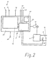
- FIG. 2 shows a basic circuit diagram of a device for regulating the temperature of a charge air flow in an embodiment according to the invention.
- the core of the control device is a control circuit 7, which is connected on the input side to a sensor combination 8, which has a humidity sensor 9 and a first temperature sensor 10, and optionally to a pressure sensor 11 or a load sensor 13 and a speed sensor 14.
- a second temperature sensor 15 for measuring the charge air temperature, a supply voltage source 12, and a signal input 16 for an external setpoint specification for the charge air temperature are also connected to the control circuit 7.
- the sensor combination 8 serves, as will be explained in more detail below, for measuring the air humidity and the temperature of the charge air. The measurement is carried out when the sensor combination 8 is arranged at the measuring point A under atmospheric conditions and when the sensor combination 8 is arranged at the measuring point B under boost pressure conditions.
- control circuit 7 On the output side, the control circuit 7 is connected to a motor-adjustable three-way valve 17 which influences the coolant flow of the charge air cooler 4 in terms of quantity or temperature.
- the charge air cooler 4 is used in a manner known per se for cooling the charge air flow coming from the turbocharger 2.
- the control circuit 7 has a humidity evaluation circuit 18 and a regulator circuit 19 for controlling the three-way valve 17.
- the air moisture evaluation circuit 18, which is designed, for example, as a microprocessor the respective dew temperature is determined from the values (air humidity and temperature) of the intake air or the charge air measured with the sensor combination 8.
- a signal corresponding to the determined dew temperature is then supplied to the control circuit 19 together with signals which correspond to the instantaneous load and speed or the instantaneous boost pressure of the internal combustion engine and the temperature of the charge air in the charge air line 5.
- the controller circuit 19 forms control signals for controlling the three-way valve 17 from these input signals with the aid of assignment tables stored in a memory 20 in such a way that a charge air temperature is obtained at the measuring point B which is significantly above the determined thaw temperature.
- the arrangement of the sensor combination 8 there are two possible arrangements for the arrangement of the sensor combination 8, namely an arrangement at measuring point A and an arrangement at measuring point B.
- a charge air temperature must be assigned to a determined thaw temperature to use one or the other of the at least two assignment tables stored in the memory, as will be explained in more detail below. Since the decision for one or the other measuring point does not influence the functional principle or the structure of the present charge air temperature control device, the exemplary embodiment serving to explain the present invention is left uniform.
- a first exemplary embodiment (“measuring point A") and a second exemplary embodiment (“measuring point B") are therefore not described - also for the sake of clarity in explaining the invention.
- the air humidity and the temperature of the intake air are measured under atmospheric conditions.
- the atmospheric thaw temperature is determined from these values.
- the charge air is at a substantially higher pressure, so that the atmospheric dew temperature is converted into the "true" dew temperature valid under charge pressure conditions on the basis of the value of the charge air pressure measured with the pressure sensor 11 got to.
- the sensor combination 8 is arranged at the measuring point B, the air humidity and the temperature of the charge air are measured under instantaneous boost pressure conditions, and a direct determination of the true thaw temperature in the charge air line 5 is thus possible.
- the decision for measuring point B has the disadvantage that the sensor combination 8 is exposed to strong vibrations and that it can also be easily damaged during maintenance work on the internal combustion engine.
- this also applies to the boost pressure sensor 11.
- the charge pressure sensor 11 When accepting a charge air temperature that is independent of boost pressure and engine load, i.e. If the charge air temperature curve, which is dependent on the dew temperature, is uniformly related to the maximum charge pressure, the charge pressure sensor 11, the load sensor 13 and the speed sensor 14 can be omitted. This can be advantageous for engines that are operated at a constant speed, since a high charge air temperature at part load is sometimes desired to improve combustion.
- the decision for one or the other arrangement of the sensor combination 8 is essentially determined by the amount of measuring equipment required in the particular application. If the charge air temperature is only to be regulated for a single internal combustion engine, the decision is probably determined thereby be what risk of damage to the sensor combination 8 the user of the internal combustion engine wants to take. If, on the other hand, the charge air temperature is to be controlled for a multi-engine system, it will make sense to arrange the sensor combination 8 at measuring point A or, which makes no difference in terms of effectiveness, outside the intake line 1 at a central point in the machine room with respect to the multi-engine system and thus the charge air temperature to regulate all internal combustion engines of the multi-engine system on the basis of the values measured with a single moisture measuring device 21.
- the sensor combination 8 and the air humidity evaluation circuit 18 form the essential elements of a moisture measuring device 21, while the controller circuit 19 including the memory 20 for the allocation tables represent the essential elements of a charge air temperature controller 22.
- the controller 22 is switched from internal setpoint specification to external setpoint specification. From this point on, the charge air temperature setpoint is set by the moisture measuring device 21. An increase in the charge air temperature prevents a failure of the water bound in the charge air caused by the recooling.
- the charge air temperature is monitored simultaneously by the second temperature sensor 15.
- a signal output 23 offers the possibility of receiving a signal generated by the air humidity evaluation circuit 18 in the event of a supply voltage failure or in the event of a malfunction of the sensor combination 8 and of supplying it to a signaling device (not shown) in a monitoring device (also not shown) at the control center of the internal combustion engine.
Landscapes
- Engineering & Computer Science (AREA)
- Physics & Mathematics (AREA)
- Thermal Sciences (AREA)
- Chemical & Material Sciences (AREA)
- Combustion & Propulsion (AREA)
- Mechanical Engineering (AREA)
- General Engineering & Computer Science (AREA)
- Combined Controls Of Internal Combustion Engines (AREA)
- Supercharger (AREA)
Claims (7)
- Dispositif pour régler la température de l'air de suralimentation d'un moteur à combustion interne à suralimentation, comportant des premiers moyens de mesure (9, 10) servant à mesurer l'humidité et la température d'un courant d'air d'alimentation aspiré par un turbocompresseur (2), et des seconds moyens de mesure (11, 15) servant à mesurer la pression et la température du courant d'air de suralimentation lorsqu'il quitte un refroidisseur d'air de suralimentation (4) traversé par ce courant d'air de suralimentation, un circuit (18) d'évaluation de l'humidité de l'air servant à déterminer le point de rosée de l'air de suralimentation à partir de signaux envoyés par les premiers moyens de mesure (9, 10) et un circuit de réglage (19) servant à déterminer une valeur de prédétermination de la température de l'air de suralimentation à partir de signaux transmis par le circuit (18) d'évaluation de l'humidité de l'air, des seconds moyens de mesure (11, 15) et une mémoire (20), dans laquelle sont mémorisés des tableaux donnant l'association entre des températures de l'air de suralimentation et des points de rosée, et pour la formation d'un signal de sortie, qui sert à commander un élément (17), qui influe sur l'action de refroidissement du refroidisseur d'air de suralimentation (4) de manière qu'on ne tombe pas au-dessous du point de rosée déterminé.
- Dispositif selon la revendication 1, caractérisé en ce qu'il est prévu comme premiers moyens de mesure, une combinaison de capteurs (8) comprenant un capteur d'humidité (9) et un premier capteur de température (10).
- Dispositif selon la revendication 1 ou 2, caractérisé en ce qu'il est prévu comme second moyen de mesure un capteur (11) de la pression de suralimentation et un second capteur de température (15).
- Dispositif selon l'une des revendications 1 à 3, caractérisé en ce que les premiers moyens de mesure (9, 10) sont disposés en amont du turbocompresseur (2), sur le trajet du courant d'air de suralimentation.
- Dispositif selon la revendication 4, caractérisé en ce que les premiers moyens de mesure (9, 10) sont disposés, dans le cas d'une installation à plusieurs moteurs, en un emplacement central par rapport à cette installation à plusieurs moteurs, à l'extérieur de conduits d'aspiration (1) associés aux différents turbocompresseurs (2).
- Dispositif selon l'une des revendications 1 à 3, caractérisé en ce que les premiers moyens de mesure (9) sont disposés en aval du refroidisseur d'air de suralimentation (4) sur le trajet du courant d'air de suralimentation.
- Dispositif selon l'une des revendications 1 à 6, caractérisé en ce qu'il est prévu, comme autres moyens de mesure (13, 14), un générateur de charge (13) et un générateur de vitesse de rotation (14).
Applications Claiming Priority (2)
| Application Number | Priority Date | Filing Date | Title |
|---|---|---|---|
| DE4109320 | 1991-03-21 | ||
| DE4109320A DE4109320C2 (de) | 1991-03-21 | 1991-03-21 | Vorrichtung zur Regelung der Ladelufttemperatur einer Brennkraftmaschine in Abhängigkeit von der Tautemperatur der Ladeluft |
Publications (2)
| Publication Number | Publication Date |
|---|---|
| EP0508068A1 EP0508068A1 (fr) | 1992-10-14 |
| EP0508068B1 true EP0508068B1 (fr) | 1994-05-25 |
Family
ID=6427901
Family Applications (1)
| Application Number | Title | Priority Date | Filing Date |
|---|---|---|---|
| EP92102800A Expired - Lifetime EP0508068B1 (fr) | 1991-03-21 | 1992-02-20 | Système de régulation de la température de la charge pour un moteur à combustion interne |
Country Status (4)
| Country | Link |
|---|---|
| EP (1) | EP0508068B1 (fr) |
| JP (1) | JPH0598971A (fr) |
| DE (2) | DE4109320C2 (fr) |
| FI (1) | FI105229B (fr) |
Families Citing this family (8)
| Publication number | Priority date | Publication date | Assignee | Title |
|---|---|---|---|---|
| DK172262B1 (da) * | 1995-10-10 | 1998-02-09 | Man B & W Diesel Gmbh | Flermotoranlæg med fælles ferskvandskølesystem |
| DE19911251C2 (de) * | 1999-02-25 | 2001-02-15 | Man B & W Diesel As Kopenhagen | Verfahren und Vorrichtung zur Detektion des Wassergehalts in einem verdichteten Luftstrom |
| WO2009002233A1 (fr) * | 2007-06-26 | 2008-12-31 | Volvo Lastvagnar Ab | Système à air de suralimentation et procédé de fonctionnement d'un système à air de suralimentation |
| AT508010B1 (de) | 2008-09-26 | 2010-10-15 | Ge Jenbacher Gmbh & Co Ohg | Brennkraftmaschine |
| EP2278134B1 (fr) * | 2009-06-26 | 2014-10-15 | H. Cegielski - SERVICE Sp.z.o.o. | Procédé pour définir les paramètres de fonctionnement pour l'unité de ligne de piston-cylindre dans les moteurs à deux temps à allumage par compression à basse vitesse |
| FI124096B (fi) * | 2009-12-17 | 2014-03-14 | Wärtsilä Finland Oy | Menetelmä mäntämoottorin käyttämiseksi |
| JP5599442B2 (ja) * | 2012-10-01 | 2014-10-01 | ボルボ ラストバグナー アーベー | チャージエアシステム及びチャージエアシステム動作方法 |
| EP2881560B1 (fr) | 2013-12-04 | 2016-09-14 | Claußen Stefan | Procédé et appareil permettant d'indiquer le risque de corrosion ou d'érosion de composants d'une chambre de combustion d'un agencement de moteur à turbocompresseur, en particulier pour des navires et agencements de moteur turbocompressé pour navires |
Citations (1)
| Publication number | Priority date | Publication date | Assignee | Title |
|---|---|---|---|---|
| DE3024209A1 (de) * | 1979-07-02 | 1981-01-22 | Guenter Dr Rinnerthaler | Fluessigkeitskuehlung fuer verbrennungsmotoren |
Family Cites Families (4)
| Publication number | Priority date | Publication date | Assignee | Title |
|---|---|---|---|---|
| DE1270885B (de) * | 1963-11-26 | 1968-06-20 | Caterpillar Tractor Co | Kuehleinrichtung |
| DE3002701A1 (de) * | 1980-01-25 | 1981-07-30 | M.A.N. Maschinenfabrik Augsburg-Nürnberg AG, 8900 Augsburg | Aufladesystem fuer eine brennkraftmaschine |
| DE3200682A1 (de) * | 1982-01-13 | 1983-07-21 | Klöckner-Humboldt-Deutz AG, 5000 Köln | Fluessigkeitsgekuehlte brennkraftmaschine mit aufladung |
| JPS61198537U (fr) * | 1985-06-01 | 1986-12-11 |
-
1991
- 1991-03-21 DE DE4109320A patent/DE4109320C2/de not_active Expired - Fee Related
-
1992
- 1992-02-20 EP EP92102800A patent/EP0508068B1/fr not_active Expired - Lifetime
- 1992-02-20 DE DE59200180T patent/DE59200180D1/de not_active Expired - Lifetime
- 1992-02-28 FI FI920908A patent/FI105229B/fi not_active IP Right Cessation
- 1992-03-13 JP JP4089802A patent/JPH0598971A/ja active Pending
Patent Citations (1)
| Publication number | Priority date | Publication date | Assignee | Title |
|---|---|---|---|---|
| DE3024209A1 (de) * | 1979-07-02 | 1981-01-22 | Guenter Dr Rinnerthaler | Fluessigkeitskuehlung fuer verbrennungsmotoren |
Also Published As
| Publication number | Publication date |
|---|---|
| FI920908A0 (fi) | 1992-02-28 |
| DE4109320C2 (de) | 1993-10-14 |
| DE4109320A1 (de) | 1992-09-24 |
| FI920908A (fi) | 1992-09-22 |
| EP0508068A1 (fr) | 1992-10-14 |
| DE59200180D1 (de) | 1994-06-30 |
| JPH0598971A (ja) | 1993-04-20 |
| FI105229B (fi) | 2000-06-30 |
Similar Documents
| Publication | Publication Date | Title |
|---|---|---|
| DE3608417C2 (fr) | ||
| DE10215262B4 (de) | Kühlsystem, insbesondere für einen Kraftfahrzeugmotor mit indirekter Ladeluftkühlung | |
| EP1030050B1 (fr) | Système de recirculation de gaz d'échappement | |
| DE3810174C2 (de) | Einrichtung zur Regelung der Kühlmitteltemperatur einer Brennkraftmaschine, insbesondere in Kraftfahrzeugen | |
| DE3801891C1 (fr) | ||
| EP0508068B1 (fr) | Système de régulation de la température de la charge pour un moteur à combustion interne | |
| DE3620288A1 (de) | Kuehlmittelsystem und verfahren zu dessen steuerung | |
| DE102010054448A1 (de) | Verfahren und Vorrichtung zur Steuerung einer Flugzeugklimaanlage | |
| EP0621921B1 (fr) | Procede pour le fonctionnement d'un moteur diesel marin | |
| DE3238191C2 (fr) | ||
| EP1121515A1 (fr) | Circuit de refroidissement d'un moteur a combustion interne | |
| DE3142643C2 (fr) | ||
| DE3300556C2 (de) | Vorrichtung zum Steuern eines Kraftfahrzeuglüfters | |
| DE4106541A1 (de) | Verfahren zur temperatursteuerung und regelung von abgassonden | |
| DE2619762A1 (de) | Warmluftheizgeraet | |
| DE4446903A1 (de) | Integrierter Luft-/Kraftstoffverhältnis-Sensor mit Vorwärtsregelung für Brenngasmotoren | |
| EP1270895A1 (fr) | Contrôle de température d'air de suralimentation pour moteurs avec refroidisseur d'air | |
| DE2610378C3 (de) | Kühlkreis für einen aufgeladenen wassergekühlten Verbrennungsmotor | |
| DE3231766C2 (fr) | ||
| DE4106684A1 (de) | Vorrichtung zur gesteuerten luftzufuhr zu mehreren baueinheiten | |
| WO1998015726A1 (fr) | Procede de controle de regulation du circuit de refroidissement d'un vehicule au moyen d'une pompe hydraulique thermoregulee | |
| WO1989011585A1 (fr) | Moteur multicylindre a combustion interne | |
| EP0239842B1 (fr) | Procédé de réglage de la température intérieure d'un habitacle, notamment d'un véhicule automobile | |
| DE2523436A1 (de) | Fluessigkeitskuehlsystem fuer eine brennkraftmaschine | |
| EP0998633A1 (fr) | Dispositif permettant de supprimer les cognements de moteurs a combustion interne |
Legal Events
| Date | Code | Title | Description |
|---|---|---|---|
| PUAI | Public reference made under article 153(3) epc to a published international application that has entered the european phase |
Free format text: ORIGINAL CODE: 0009012 |
|
| AK | Designated contracting states |
Kind code of ref document: A1 Designated state(s): DE FR IT NL |
|
| 17P | Request for examination filed |
Effective date: 19921028 |
|
| 17Q | First examination report despatched |
Effective date: 19930205 |
|
| ITF | It: translation for a ep patent filed |
Owner name: BARZANO' E ZANARDO ROMA S.P.A. |
|
| GRAA | (expected) grant |
Free format text: ORIGINAL CODE: 0009210 |
|
| AK | Designated contracting states |
Kind code of ref document: B1 Designated state(s): DE FR IT NL |
|
| REF | Corresponds to: |
Ref document number: 59200180 Country of ref document: DE Date of ref document: 19940630 |
|
| ET | Fr: translation filed | ||
| PLBE | No opposition filed within time limit |
Free format text: ORIGINAL CODE: 0009261 |
|
| STAA | Information on the status of an ep patent application or granted ep patent |
Free format text: STATUS: NO OPPOSITION FILED WITHIN TIME LIMIT |
|
| 26N | No opposition filed | ||
| PGFP | Annual fee paid to national office [announced via postgrant information from national office to epo] |
Ref country code: FR Payment date: 20110302 Year of fee payment: 20 Ref country code: IT Payment date: 20110221 Year of fee payment: 20 Ref country code: DE Payment date: 20110218 Year of fee payment: 20 Ref country code: NL Payment date: 20110216 Year of fee payment: 20 |
|
| REG | Reference to a national code |
Ref country code: DE Ref legal event code: R071 Ref document number: 59200180 Country of ref document: DE |
|
| REG | Reference to a national code |
Ref country code: DE Ref legal event code: R071 Ref document number: 59200180 Country of ref document: DE |
|
| REG | Reference to a national code |
Ref country code: NL Ref legal event code: V4 Effective date: 20120220 |
|
| PG25 | Lapsed in a contracting state [announced via postgrant information from national office to epo] |
Ref country code: DE Free format text: LAPSE BECAUSE OF EXPIRATION OF PROTECTION Effective date: 20120221 |