EP0508028B1 - Process for connecting two pipe sections and the pipe joint thus formed - Google Patents
Process for connecting two pipe sections and the pipe joint thus formed Download PDFInfo
- Publication number
- EP0508028B1 EP0508028B1 EP91810256A EP91810256A EP0508028B1 EP 0508028 B1 EP0508028 B1 EP 0508028B1 EP 91810256 A EP91810256 A EP 91810256A EP 91810256 A EP91810256 A EP 91810256A EP 0508028 B1 EP0508028 B1 EP 0508028B1
- Authority
- EP
- European Patent Office
- Prior art keywords
- tube
- section
- cross
- thinner
- rung
- Prior art date
- Legal status (The legal status is an assumption and is not a legal conclusion. Google has not performed a legal analysis and makes no representation as to the accuracy of the status listed.)
- Expired - Lifetime
Links
- 238000000034 method Methods 0.000 title claims abstract description 18
- 230000035515 penetration Effects 0.000 claims abstract description 9
- 229910001220 stainless steel Inorganic materials 0.000 claims abstract description 6
- 239000010935 stainless steel Substances 0.000 claims abstract description 6
- 238000007906 compression Methods 0.000 claims description 11
- 230000006835 compression Effects 0.000 claims description 8
- 230000007704 transition Effects 0.000 claims description 3
- 230000008859 change Effects 0.000 abstract description 2
- 229910000831 Steel Inorganic materials 0.000 description 2
- 230000008901 benefit Effects 0.000 description 2
- 230000015572 biosynthetic process Effects 0.000 description 2
- VNNRSPGTAMTISX-UHFFFAOYSA-N chromium nickel Chemical compound [Cr].[Ni] VNNRSPGTAMTISX-UHFFFAOYSA-N 0.000 description 2
- 239000010959 steel Substances 0.000 description 2
- 238000003466 welding Methods 0.000 description 2
- 229910000669 Chrome steel Inorganic materials 0.000 description 1
- XAGFODPZIPBFFR-UHFFFAOYSA-N aluminium Chemical compound [Al] XAGFODPZIPBFFR-UHFFFAOYSA-N 0.000 description 1
- 229910052782 aluminium Inorganic materials 0.000 description 1
- 239000004020 conductor Substances 0.000 description 1
- 230000007797 corrosion Effects 0.000 description 1
- 238000005260 corrosion Methods 0.000 description 1
- 230000000694 effects Effects 0.000 description 1
- 238000003780 insertion Methods 0.000 description 1
- 230000037431 insertion Effects 0.000 description 1
- 230000000149 penetrating effect Effects 0.000 description 1
- 230000007480 spreading Effects 0.000 description 1
- 230000008719 thickening Effects 0.000 description 1
- 238000002054 transplantation Methods 0.000 description 1
Images
Classifications
-
- E—FIXED CONSTRUCTIONS
- E06—DOORS, WINDOWS, SHUTTERS, OR ROLLER BLINDS IN GENERAL; LADDERS
- E06C—LADDERS
- E06C7/00—Component parts, supporting parts, or accessories
- E06C7/08—Special construction of longitudinal members, or rungs or other treads
- E06C7/082—Connections between rungs or treads and longitudinal members
- E06C7/086—Connections between rungs or treads and longitudinal members with a connecting piece inserted in a hollow rung
-
- F—MECHANICAL ENGINEERING; LIGHTING; HEATING; WEAPONS; BLASTING
- F16—ENGINEERING ELEMENTS AND UNITS; GENERAL MEASURES FOR PRODUCING AND MAINTAINING EFFECTIVE FUNCTIONING OF MACHINES OR INSTALLATIONS; THERMAL INSULATION IN GENERAL
- F16B—DEVICES FOR FASTENING OR SECURING CONSTRUCTIONAL ELEMENTS OR MACHINE PARTS TOGETHER, e.g. NAILS, BOLTS, CIRCLIPS, CLAMPS, CLIPS OR WEDGES; JOINTS OR JOINTING
- F16B7/00—Connections of rods or tubes, e.g. of non-circular section, mutually, including resilient connections
- F16B7/04—Clamping or clipping connections
- F16B7/0433—Clamping or clipping connections for rods or tubes being in parallel relationship
-
- F—MECHANICAL ENGINEERING; LIGHTING; HEATING; WEAPONS; BLASTING
- F16—ENGINEERING ELEMENTS AND UNITS; GENERAL MEASURES FOR PRODUCING AND MAINTAINING EFFECTIVE FUNCTIONING OF MACHINES OR INSTALLATIONS; THERMAL INSULATION IN GENERAL
- F16L—PIPES; JOINTS OR FITTINGS FOR PIPES; SUPPORTS FOR PIPES, CABLES OR PROTECTIVE TUBING; MEANS FOR THERMAL INSULATION IN GENERAL
- F16L41/00—Branching pipes; Joining pipes to walls
- F16L41/08—Joining pipes to walls or pipes, the joined pipe axis being perpendicular to the plane of the wall or to the axis of another pipe
- F16L41/082—Non-disconnectible joints, e.g. soldered, adhesive or caulked joints
Definitions
- the present invention relates to a method for connecting two at least approximately perpendicular pipe pieces, which are different in diameter.
- the method is particularly suitable for connecting ladder rungs and ladder bars made of stainless steel, the end of the thinner tube section being pressed in a known manner through a jacket bore in the thicker tube against the inner wall thereof. In this way, the tube end of the thinner tube extending into the bore is compressed or braced outwards.
- This method which is particularly suitable for connecting aluminum pipe pieces, can hardly be used for pipe pieces made of chromium-nickel steel, since a chromium-nickel steel pipe can only be compressed or tensioned by the application of greater forces, the compression spreading uncontrollably along the pipe and leads to damage to the pipe, or instead of a rounded collapsing collar there is an indefinable fold formation with diagonal distortion of the muntin pipe.
- the rungs of chrome steel ladders must therefore be welded or riveted, although the welding or riveting points are very susceptible to corrosion.
- the invention is based on the object of proposing a method by means of which the disadvantages mentioned can be avoided, wherein a compression ring or bulge with a predetermined diameter should be formed when the thinner conductor tube is pressed in by a jacket bore thereof. It is also intended to prevent a bulge-shaped thickening with an indefinite shape from occurring instead of a compression ring, which extends far along the rung tube and seriously jeopardizes its stability.
- this object is achieved in a method as described in the preamble of claim 1 by the features in the characterizing part of claim 1.
- This is understood to mean a procedure in which the end of the tube to be compressed remains unchanged in cross-section in cross section before the compression process and, to limit the extent of the compression process, also compressing part, part of the muntin tube to be compressed is deformed in cross section.
- This deformation can consist in the flattening of the corresponding part of the rung tube, which will thereby additionally have a particularly suitable non-slip foot rest or tread surface.
- the method can preferably be carried out by first inserting a plug having a conical section into the end of the thinner tube to be connected and then, together with the thinner tube, the plug being pressed through the jacket bore of the thicker tube against the inner wall thereof, whereby the thinner tube, in order to limit the penetration of the conical part into it, is previously locally deformed in cross section.
- transition point between the deformed and non-deformed part of the tube forms a limit stop, which reliably prevents further penetration of the conical part into the thinner tube. If a part of the thinner pipe is flattened to a tread surface, the transitions on both sides of the flattened part of the pipe cross-section at the beginning and end form the longitudinal limitation of the compressed parts, which prevent the associated plug from penetrating further.
- the invention further relates to a pipe connection produced by the method between a ladder spar and a ladder rung, which may consist of stainless steel.
- the pipe joint has a rung with at least one locally limited cross-sectional deformation, which locally limits the compression of the rung end in the ladder stile.
- plugs are inserted into the ends of the ladder rungs, they have a conical shaft and a round protruding head which is shaped in accordance with the inner curvature of the ladder spar.
- the penetration of the conical shaft into the rung tube is again due to a local change in cross section of the rung tube limited.
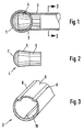
- the pipe connection made of stainless steel can be used between a ladder bar 1 and a ladder rung 2, which is smaller in diameter than the bar 1.
- the end 3 of the rung 2 is guided through a jacket bore of the thicker tube, here the ladder stile 1, after a plug 4 has been inserted into the said rung end.
- the plug 4 can be seen in FIG. 2 and is preferably made of plastic.
- the conical stopper is provided with a cylindrically tapering shaft 5 and with a subsequent, comically widening part 6, which at the other end merges into a semicircular, projecting head 7.
- This head 7 is preferably shaped in accordance with the inner curvature of the ladder stile 1.
- the end 3 of the rung 2 is round in cross section, while the middle rung part is deformed outside the plug used. This deformed part is shown graphically in FIG. 3. It can be seen that the rung 2 is equipped with longitudinal notches 8, which at the same time forms a widened foot rest 9. It is of course also possible to provide a different deformation instead of the longitudinal notch. Longitudinal ribs 10 can expediently be used, which must end at the point at which the penetration of the stopper 4 should be stopped.
- the flattened footrest formed can be provided with limiting ribs which rise above the surface of the footrest which is not wavy in cross section and thus form a sliding footrest.
- the cylindrical shaft 5 of the stopper 4 is inserted into the end of the rung 2 which is round in cross section, and the rung 2 together with stopper 4 is inserted into the interior of the latter through the jacket bore of the ladder stile 1, so that the round, projecting head 7 counteracts the inner wall of the ladder stile 1 comes to rest.
- the rung 2 is moved relative to the stopper 4 and the end of the rung 2 is driven apart by the conically widened part 6 of the stopper 4, so that the edge part of the rung end 2 is deformed or clamped into a compression ring.
- the deformation is limited by the fact that the rung 2 is not moved against the stopper 4 without restriction can, but only so far until the deformed shape or the end of the rib 10 abuts the end of the cylindrical shaft 5.
- the substantially reduced cross-sectional area of the rung 2 no longer allows the same to be moved relative to the stopper 4. This reliably prevents further transplantation of the upset formation, so that neither the ladder stile nor the rung can be damaged or deformed.
- connection described may possibly can also be used without a plug.
- the ladder rung is inserted directly through the jacket hole and pressed against the inner wall of the ladder stile 1.
- the end of the ladder rung 2 is then compressed, the compression effect only extending to the point at which the rung is deformed in cross section.
- the simplified design described last is often sufficient to meet the requirements, and this solution can be carried out more cost-effectively.
- the insertion of the stopper has the advantage that the tube weakened by the bore is considerably strengthened and stabilized. This is also an advantage over a rung attachment by welding.
Abstract
Description
Die vorliegende Erfindung bezieht sich auf ein Verfahren zum Verbinden zweier zumindest annähernd senkrecht zueinander stehender Rohrstücke, welche im Durchmesser verschieden sind. Das Verfahren eignet sich insbesondere zum Verbinden von Leitersprossen und Leiterholmen aus rostfreiem Stahl, wobei das Ende des dünneren Rohrstücks in bekannter Weise durch eine Mantelbohrung des dickeren Rohrs gegen die Innenwand desselben gepresst wird. In dieser Weise wird das sich in die Bohrung erstreckende Rohrende des dünneren Rohrs gestaucht bzw. nach aussen verspannt. Dieses Verfahren, welches sich besonders zum Verbinden vom Aluminiumrohrstücken eignet, kann schwerlich für Rohrstücke aus Chromnickelstahl verwendet werden, da ein Chromnickelstahl-Rohr nur durch die Anwendung von grösseren Kräften gestaucht bzw. verspannt werden kann, wobei die Stauchung sich unkontrollierbar entlang des Rohrs ausbreitet und zur Beschädigung des Rohrs führt, oder es entsteht anstelle eines rundlichen Stauchkragens eine undefinierbare Faltenbildung mit Diagonalverzug des Sprossenrohrs. Die Sprossen von Chromstahlleitern müssen deshalb geschweisst oder genietet werden, wobei jedoch bei diesem Vorgehen die Schweiss- oder Nietstellen sehr stark korrosionsgefährdet sind.The present invention relates to a method for connecting two at least approximately perpendicular pipe pieces, which are different in diameter. The method is particularly suitable for connecting ladder rungs and ladder bars made of stainless steel, the end of the thinner tube section being pressed in a known manner through a jacket bore in the thicker tube against the inner wall thereof. In this way, the tube end of the thinner tube extending into the bore is compressed or braced outwards. This method, which is particularly suitable for connecting aluminum pipe pieces, can hardly be used for pipe pieces made of chromium-nickel steel, since a chromium-nickel steel pipe can only be compressed or tensioned by the application of greater forces, the compression spreading uncontrollably along the pipe and leads to damage to the pipe, or instead of a rounded collapsing collar there is an indefinable fold formation with diagonal distortion of the muntin pipe. The rungs of chrome steel ladders must therefore be welded or riveted, although the welding or riveting points are very susceptible to corrosion.
Aus der DE-PS 826 246 ist ein Verfahren zum Verbinden zweier Rohre der gattungsgemässen Art bekannt, bei welchem die zu stauchenden Enden des dünneren Rohrs geschlitzt werden. In diese geschlitzten Enden wird ein konischer Dorn eingeführt, welcher beim Einpressen des dünneren Rohrs in eine Mantelbohrung des dickeren Rohrs in das Ende des dünneren Rohrs hineingedrückt wird und dadurch dieses im geschlitzten Bereich aufweitet. Mit diesem Verfahren kann jedoch kein für eine Zuverlässige hochbelastbare Verbindung erforderlicher, eigentlicher Stauchwulst definierter Grösse und mit definierter Lage ausgebildet werden.From DE-PS 826 246 a method for connecting two tubes of the generic type is known, in which the ends of the thinner tube to be compressed are slotted. A conical mandrel is inserted into these slotted ends, which is pressed into the end of the thinner tube when the thinner tube is pressed into a jacket bore of the thicker tube, thereby widening the latter in the slotted area. With this method, however, no actual bulge of a defined size and with a defined position, which is required for a reliable, high-strength connection, can be formed.
Der Erfindung liegt die Aufgabe zugrunde, ein Verfahren vorzuschlagen, mittels welchem die erwähnten Nachteile vermieden werden können, wobei beim Einpressen des dünneren Leiterrohrs durch eine Mantelbohrung desselben ein Stauchring oder -wulst mit vorbestimmtem Durchmesser gebildet werden sollte. Dabei soll auch verhindert werden, dass anstelle eines Stauchrings eine wulstförmige Verdickung mit unbestimmter Form entsteht, welche sich weit entlang des Sprossenrohrs erstreckt und die Stabilität desselben ernstlich gefährdet.The invention is based on the object of proposing a method by means of which the disadvantages mentioned can be avoided, wherein a compression ring or bulge with a predetermined diameter should be formed when the thinner conductor tube is pressed in by a jacket bore thereof. It is also intended to prevent a bulge-shaped thickening with an indefinite shape from occurring instead of a compression ring, which extends far along the rung tube and seriously jeopardizes its stability.
Erfindungsgemäss wird diese Aufgabe bei einem Verfahren, wie im Oberbegriff von Anspruch 1 beschrieben, durch die Merkmale im Kennzeichen des Anspruchs 1 gelöst. Darunter wird ein Vorgehen verstanden, bei welchem das Ende des zu stauchenden Rohrs vor dem Stauchvorgang im Querschnitt unverändert kreisringförmig bleibt und, zur Begrenzung der Ausdehnung des Stauchvorgangs am zu stauchenden Teil, ein Teil des zu stauchenden Sprossenrohrs im Querschnitt deformiert wird. Diese Deformation kann in der Verflachung des entsprechenden Teils des Sprossenrohrs bestehen, welches dadurch zusätzlich noch eine besonders geeignete abgleitsichere Fussraste bzw. Trittfläche aufweisen wird.According to the invention, this object is achieved in a method as described in the preamble of claim 1 by the features in the characterizing part of claim 1. This is understood to mean a procedure in which the end of the tube to be compressed remains unchanged in cross-section in cross section before the compression process and, to limit the extent of the compression process, also compressing part, part of the muntin tube to be compressed is deformed in cross section. This deformation can consist in the flattening of the corresponding part of the rung tube, which will thereby additionally have a particularly suitable non-slip foot rest or tread surface.
Das Verfahren kann in bevorzugter Weise so durchgeführt werden, dass in das zu verbindende Ende des dünneren Rohrs zunächst ein, einen konischen Abschnitt aufweisender Stopfen eingeführt und dieser anschliessend, samt dünnerem Rohr, durch die Mantelbohrung des dickeren Rohrs gegen die Innenwand desselben gepresst wird, wobei das dünnere Rohr, zum Begrenzen des Eindringens des konischen Teils in dasselbe, vorgängig örtlich im Querschnitt deformiert wird.The method can preferably be carried out by first inserting a plug having a conical section into the end of the thinner tube to be connected and then, together with the thinner tube, the plug being pressed through the jacket bore of the thicker tube against the inner wall thereof, whereby the thinner tube, in order to limit the penetration of the conical part into it, is previously locally deformed in cross section.
Die Übergangsstelle zwischen dem deformierten und nicht-deformierten Teil des Rohrs bildet einen Grenzanschlag, welcher ein weiteres Eindringen des konischen Teils in das dünnere Rohr zuverlässig verhindert. Wird ein Teil des dünneren Rohrs zu einer Trittfläche verflacht, so bilden die beidseitigen Übergänge des verflachten Teils des am Anfang und am Ende vorhandenen Rohrquerschnitts die Längsbegrenzung der gestauchten Teile, welche das Weitereindringen des zugehörigen Stopfens verhindern.The transition point between the deformed and non-deformed part of the tube forms a limit stop, which reliably prevents further penetration of the conical part into the thinner tube. If a part of the thinner pipe is flattened to a tread surface, the transitions on both sides of the flattened part of the pipe cross-section at the beginning and end form the longitudinal limitation of the compressed parts, which prevent the associated plug from penetrating further.
Die Erfindung bezieht sich ferner auf eine nach dem Verfahren hergestellte Rohrverbindung zwischen einem Leiterholm und einer Leitersprosse, die aus rostfreiem Stahl bestehen kann. Die Rohrverbindung weist eine Sprosse mit mindestens einer örtlich begrenzten Querschnittsdeformation auf, welche das Stauchen des Sprossenendes im Leiterholm örtlich begrenzt.The invention further relates to a pipe connection produced by the method between a ladder spar and a ladder rung, which may consist of stainless steel. The pipe joint has a rung with at least one locally limited cross-sectional deformation, which locally limits the compression of the rung end in the ladder stile.
Werden in die Enden der Leitersprossen Stopfen eingesetzt, so weisen diese einen konischen Schaft und einen runden vorstehenden Kopf auf, welcher der Innenwölbung des Leiterholms entsprechend geformt ist. Das Eindringen des konischen Schafts in das Sprossenrohr wird wieder durch eine örtliche Querschnittsänderung des Sprossenrohrs begrenzt.If plugs are inserted into the ends of the ladder rungs, they have a conical shaft and a round protruding head which is shaped in accordance with the inner curvature of the ladder spar. The penetration of the conical shaft into the rung tube is again due to a local change in cross section of the rung tube limited.
Auf beiliegender Zeichnung ist ein Ausführungsbeispiel einer Rohrverbindung schematisch dargestellt, aufgrund deren auch das Verfahren näher erläutert wird. Es zeigen:
- Fig. 1
- eine schematisch gezeichnete Rohrverbindung, teilweise im Schnitt;
- Fig. 2
- einen in Verbindung mit der Rohrverbindung zu gebrauchenden Stopfen; und
- Fig. 3
- das Sprossenrohr aus Fig. 1, welches entlang der
Ebene 3/3 der Fig. 1 geschnitten ist.
- Fig. 1
- a schematically drawn pipe connection, partly in section;
- Fig. 2
- a plug to be used in connection with the pipe joint; and
- Fig. 3
- 1, which is cut along the
plane 3/3 of FIG. 1.
Die Rohrverbindung aus rostfreiem Stahl ist, wie bereits erwähnt, zwischen einem Leiterholm 1 und einer Leitersprosse 2, welche im Durchmesser kleiner ist als der Holm 1, anwendbar. Das Ende 3 der Sprosse 2 wird durch eine Mantelbohrung des dikkeren Rohrs, hier des Leiterholms 1, geführt, nachdem in das genannte Sprossenende ein Stopfen 4 eingeführt wurde. Der Stopfen 4 ist aus Fig. 2 ersichtlich und besteht vorzugsweise aus Kunststoff. Der konische Stopfen ist mit einem zylindrisch auslaufenden Schaft 5 und mit einem anschliessenden, sich komisch erweiternden Teil 6 versehen, welcher andernends in einem halbrunden, vorstehenden Kopf 7 übergeht. Dieser Kopf 7 ist vorzugsweise der Innenwölbung des Leiterholms 1 entsprechend geformt.As already mentioned, the pipe connection made of stainless steel can be used between a ladder bar 1 and a
Das Ende 3 der Sprosse 2 ist im Querschnitt rund ausgebildet, während der mittlere Sprossenteil ausserhalb des eingesetzten Stopfens deformiert ist. Dieser deformierte Teil ist in Fig. 3 schaubildlich dargestellt. Es ist dabei ersichtlich, dass die Sprosse 2 mit Längskerben 8 ausgerüstet ist, welche gleichzeitig eine verbreiterte Trittauflage 9 bildet. Es ist selbstverständlich auch möglich, anstelle der Längskerbe eine andere Deformation vorzusehen. Zweckmässigerweise können Längsrippen 10 eingesetzt werden, die an der Stelle enden müssen, an der das Eindringen des Stopfens 4 aufgehalten werden sollte. Die gebildete verflachte Trittauflage kann mit Begrenzungsrippen versehen sein, die sich über der im Querschnitt nicht wellenförmigen Oberfläche der Trittauflage erheben und somit eine gleitende Fussraste bilden.The
Zum Bilden der Verbindung wird der zylindrische Schaft 5 des Stopfens 4 in das im Querschnitt runde Ende der Sprosse 2 eingesetzt und die Sprosse 2 samt Stopfen 4 durch die Mantelbohrung des Leiterholms 1 in das Innere desselben eingeführt, so dass der runde, vorstehende Kopf 7 gegen die Innenwand des Leiterholms 1 zur Auflage kommt. Mit wachsendem Druck wird die Sprosse 2 gegenüber dem Stopfen 4 bewegt und das Ende der Sprosse 2 wird dabei durch den konisch erweiterten Teil 6 des Stopfens 4 auseinandergetrieben, so dass der Randteil des Sprossenendes 2 zu einem Stauchring verformt oder verspannt wird. Die Verformung wird aber dadurch begrenzt, dass die Sprosse 2 nicht unbeschränkt gegen den Stopfen 4 bewegt werden kann, sondern nur so weit, bis die deformierte Form oder das Ende der Rippe 10 auf das Ende des zylindrischen Schafts 5 anstösst. Die wesentlich verminderte Querschnittsfläche der Sprosse 2 erlaubt nämlich ein weiteres Verschieben derselben gegenüber dem Stopfen 4 nicht mehr. Damit wird eine Weiterverpflanzung der Stauchbildung zuverlässig verhindert, so dass weder der Leiterholm noch die Sprosse beschädigt bzw. deformiert werden kann.To form the connection, the
Die beschriebene Verbindung kann u.U. auch ohne Stopfen gebraucht werden. In diesem Falle wird die Leitersprosse direkt durch die Mantelbohrung eingeführt und gegen die Innenwand des Leiterholms 1 gepresst. Das Ende der Leitersprosse 2 wird dann gestaucht, wobei die Stauchwirkung sich nur bis zur Stelle, an welcher die Sprosse im Querschnitt deformiert wird, erstreckt.The connection described may possibly can also be used without a plug. In this case, the ladder rung is inserted directly through the jacket hole and pressed against the inner wall of the ladder stile 1. The end of the
Die zuletzt beschriebene vereinfachte Ausführung genügt oft, um den gestellten Anforderungen zu entsprechen, wobei diese Lösung kostengünstiger ausgeführt werden kann. Das Einbringen des Stopfens bringt, im Gegensatz zur einfachen Lösung, noch den Vorteil mit sich, dass das durch die Bohrung geschwächte Rohr erheblich gestärkt und stabilisiert wird. Dies ist auch ein Vorteil gegenüber einer Sprossenbefestigung durch Schweissen.The simplified design described last is often sufficient to meet the requirements, and this solution can be carried out more cost-effectively. In contrast to the simple solution, the insertion of the stopper has the advantage that the tube weakened by the bore is considerably strengthened and stabilized. This is also an advantage over a rung attachment by welding.
Claims (9)
- Method for connecting two tube sections (1, 2) lying at least approximately at right angles to each other and with different diameters, in particular for connecting ladder rungs and ladder beams of stainless steel, the end of the thinner tube section (2) of annular cross-section being pressed through a surface bore in the thicker tube (1) against the inner wall thereof, so that the tube end of the thinner tube (2) extending into the bore is compressed or braced towards the outside, characterised in that the longitudinal extent of the end of the thinner tube (2) to be compressed, before the pressing-in thereof, is defined by a cross-sectional variation of the thinner tube (2) so that the end of the thinner tube (2) to be compressed is left unchanged with a cross-section in the shape of a circular ring, whereas in order to limit the extent of the compression process on the part of the thinner tube (2) to be compressed, a part of the remaining thinner tube (2) is deformed in its cross-section.
- Method according to Claim 1, characterised in that introduced into the end to be compressed of the thinner tube (2) is first of all a plug (4) having a conical section (6) and then the latter, together with the thinner tube (2), is pressed through the surface bore of the thicker tube (1) against the inner wall thereof, in which case the thinner tube (2), for limiting the penetration of the conical section (6) into the latter, is previously deformed in cross-section locally in a limited manner.
- Method according to Claims 1 and 2, characterised in that for varying the cross-section, the thinner tube (2) is provided with longitudinal ribs, whereof the ends form a limiting abutment for the penetration of the conical section (6) or for the propagation of the compression in the longitudinal direction.
- Method according to Claims 1 and 2, characterised in that a part of the thinner tube (2) is flattened to form a tread (9), the transitions on both sides of the flattened part to the round cross-section forming the longitudinal boundaries of the compressed ends and thus for the penetration of the plugs (4).
- Tube joint produced in accordance with the method according to Claims 1 to 4 between a ladder beam (1) and a ladder rung (2) of stainless steel, characterised in that the latter comprises a rung (2) with at least one locally defined cross-sectional deformation, which at least one deformation locally defines the compression of the end of the rung in the ladder beam.
- Tube joint according to Claim 5, characterised in that inserted in the ends of the ladder rungs (2) are plugs (4), which comprise a cylindrical shaft (5), a conical section (6) and a round, projecting head (7), which is shaped to correspond to the inner curvature of the ladder beam (1), the penetration of the plug (4) into the rung tube being limited by a local cross-sectional variation thereof.
- Tube joint according to Claims 5 and 6, characterised in that the latter comprises a ladder rung (2) with a flattened tread (9), both ends of the tread (9) being constructed as a stop for limiting the plug (4) pressed into the rung tube (2).
- Tube joint according to Claims 5 to 7, characterised in that the flattened tread (9) is additionally provided with longitudinal grooves (8).
- Tube joint according to Claims 5 to 8, characterised in that the tread (9) is provided with boundary ribs, which rise above the surface of the tread having a slightly undulating cross-section.
Priority Applications (3)
| Application Number | Priority Date | Filing Date | Title |
|---|---|---|---|
| DE59107035T DE59107035D1 (en) | 1991-04-08 | 1991-04-08 | Method for connecting two pieces of pipe and pipe connection produced by the method. |
| AT91810256T ATE131251T1 (en) | 1991-04-08 | 1991-04-08 | METHOD FOR CONNECTING TWO PIECES OF PIPE AND PIPE JOINT PRODUCED BY THE METHOD. |
| EP91810256A EP0508028B1 (en) | 1991-04-08 | 1991-04-08 | Process for connecting two pipe sections and the pipe joint thus formed |
Applications Claiming Priority (1)
| Application Number | Priority Date | Filing Date | Title |
|---|---|---|---|
| EP91810256A EP0508028B1 (en) | 1991-04-08 | 1991-04-08 | Process for connecting two pipe sections and the pipe joint thus formed |
Publications (2)
| Publication Number | Publication Date |
|---|---|
| EP0508028A1 EP0508028A1 (en) | 1992-10-14 |
| EP0508028B1 true EP0508028B1 (en) | 1995-12-06 |
Family
ID=8208837
Family Applications (1)
| Application Number | Title | Priority Date | Filing Date |
|---|---|---|---|
| EP91810256A Expired - Lifetime EP0508028B1 (en) | 1991-04-08 | 1991-04-08 | Process for connecting two pipe sections and the pipe joint thus formed |
Country Status (3)
| Country | Link |
|---|---|
| EP (1) | EP0508028B1 (en) |
| AT (1) | ATE131251T1 (en) |
| DE (1) | DE59107035D1 (en) |
Cited By (2)
| Publication number | Priority date | Publication date | Assignee | Title |
|---|---|---|---|---|
| EP2722478A1 (en) | 2012-10-19 | 2014-04-23 | MSU- Normen Henri Zenhäusern AG | Ladder |
| EP3059381A1 (en) | 2015-02-20 | 2016-08-24 | MSU- Normen Henri Zenhäusern AG | Ladder |
Family Cites Families (3)
| Publication number | Priority date | Publication date | Assignee | Title |
|---|---|---|---|---|
| DE826246C (en) * | 1949-02-16 | 1951-12-27 | Karl Echterbecker | Method for connecting perpendicular pipes of different diameters, in particular the stiles and rungs of ladders |
| CH543011A (en) * | 1972-08-25 | 1973-10-15 | Zenhaeusern Heinrich | Method for connecting two pipe sections that are at least approximately perpendicular to one another |
| DE2814369C2 (en) * | 1978-04-04 | 1979-11-29 | Heinrich Urdorf Zuerich Zenhaeusern (Schweiz) | Method of making a ladder |
-
1991
- 1991-04-08 DE DE59107035T patent/DE59107035D1/en not_active Expired - Fee Related
- 1991-04-08 EP EP91810256A patent/EP0508028B1/en not_active Expired - Lifetime
- 1991-04-08 AT AT91810256T patent/ATE131251T1/en not_active IP Right Cessation
Cited By (2)
| Publication number | Priority date | Publication date | Assignee | Title |
|---|---|---|---|---|
| EP2722478A1 (en) | 2012-10-19 | 2014-04-23 | MSU- Normen Henri Zenhäusern AG | Ladder |
| EP3059381A1 (en) | 2015-02-20 | 2016-08-24 | MSU- Normen Henri Zenhäusern AG | Ladder |
Also Published As
| Publication number | Publication date |
|---|---|
| DE59107035D1 (en) | 1996-01-18 |
| EP0508028A1 (en) | 1992-10-14 |
| ATE131251T1 (en) | 1995-12-15 |
Similar Documents
| Publication | Publication Date | Title |
|---|---|---|
| DE2614830C2 (en) | Pipe arrangement | |
| DE3035867C2 (en) | ||
| DE3742496C2 (en) | Method and device for producing an end thickening on a steel pipe | |
| EP2059366B1 (en) | Method for welding components with a closed hollow cross-section in such a way that a peripheral gap is produced between the two overlapping components | |
| DE1112674B (en) | Blind rivet | |
| WO1985000646A1 (en) | Coupling device for the permanent connection of pipes | |
| DE19614656A1 (en) | Manufacture of increased wall thickness on hollow profile, for IC engine exhaust pipe | |
| DE2219196A1 (en) | Pipe coupling | |
| DE3320164A1 (en) | DEVICE AND METHOD FOR CONNECTING A TUBE PROFILE TO A SHEET ELEMENT WITH A ANGLE | |
| DE102013008351B3 (en) | Component with at least two parts welded together | |
| EP0508028B1 (en) | Process for connecting two pipe sections and the pipe joint thus formed | |
| DE1286337B (en) | Blind rivet assembly and method of manufacturing the same | |
| DE2938006C2 (en) | Device for connecting two smooth pipe ends | |
| DE4205598C1 (en) | Method of flattening cut ends of plastically deformable material - has wall of tube incised at two points prior to pressing | |
| DE826246C (en) | Method for connecting perpendicular pipes of different diameters, in particular the stiles and rungs of ladders | |
| DE3141928C2 (en) | Reinforcing bar for reinforced concrete | |
| CH684436A5 (en) | Process for connecting two pipe pieces, and pipe connection produced in accordance with the process | |
| DE4233304A1 (en) | Coupling sleeve for drill or anchor rods - comprises abutment for limiting rod end screwing distance | |
| DE10111279A1 (en) | scaffold tube | |
| DE2161161A1 (en) | Method for reshaping a glass tube end | |
| EP2722478B1 (en) | Ladder | |
| EP1574661B1 (en) | Method of joining a rung to a stile of a ladder | |
| EP3059381B1 (en) | Ladder | |
| DE2332528A1 (en) | Hose connection for vehicle hydraulic brakes - thin corrugated outer wall deformed to grip hose | |
| EP1479961B1 (en) | Crimped connection |
Legal Events
| Date | Code | Title | Description |
|---|---|---|---|
| PUAI | Public reference made under article 153(3) epc to a published international application that has entered the european phase |
Free format text: ORIGINAL CODE: 0009012 |
|
| AK | Designated contracting states |
Kind code of ref document: A1 Designated state(s): AT BE CH DE DK ES FR GB GR IT LI LU NL SE |
|
| 17P | Request for examination filed |
Effective date: 19930127 |
|
| 17Q | First examination report despatched |
Effective date: 19940901 |
|
| GRAA | (expected) grant |
Free format text: ORIGINAL CODE: 0009210 |
|
| AK | Designated contracting states |
Kind code of ref document: B1 Designated state(s): AT BE CH DE DK ES FR GB GR IT LI LU NL SE |
|
| PG25 | Lapsed in a contracting state [announced via postgrant information from national office to epo] |
Ref country code: IT Free format text: LAPSE BECAUSE OF FAILURE TO SUBMIT A TRANSLATION OF THE DESCRIPTION OR TO PAY THE FEE WITHIN THE PRE;WARNING: LAPSES OF ITALIAN PATENTS WITH EFFECTIVE DATE BEFORE 2007 MAY HAVE OCCURRED AT ANY TIME BEFORE 2007. THE CORRECT EFFECTIVE DATE MAY BE DIFFERENT FROM THE ONE RECORDED.SCRIBED TIME-LIMIT Effective date: 19951206 Ref country code: GB Effective date: 19951206 Ref country code: NL Free format text: LAPSE BECAUSE OF FAILURE TO SUBMIT A TRANSLATION OF THE DESCRIPTION OR TO PAY THE FEE WITHIN THE PRESCRIBED TIME-LIMIT Effective date: 19951206 Ref country code: GR Free format text: LAPSE BECAUSE OF FAILURE TO SUBMIT A TRANSLATION OF THE DESCRIPTION OR TO PAY THE FEE WITHIN THE PRESCRIBED TIME-LIMIT Effective date: 19951206 Ref country code: BE Effective date: 19951206 Ref country code: DK Effective date: 19951206 Ref country code: ES Free format text: THE PATENT HAS BEEN ANNULLED BY A DECISION OF A NATIONAL AUTHORITY Effective date: 19951206 |
|
| REF | Corresponds to: |
Ref document number: 131251 Country of ref document: AT Date of ref document: 19951215 Kind code of ref document: T |
|
| REF | Corresponds to: |
Ref document number: 59107035 Country of ref document: DE Date of ref document: 19960118 |
|
| REG | Reference to a national code |
Ref country code: CH Ref legal event code: NV Representative=s name: ROTTMANN, ZIMMERMANN + PARTNER AG |
|
| ET | Fr: translation filed | ||
| PG25 | Lapsed in a contracting state [announced via postgrant information from national office to epo] |
Ref country code: SE Effective date: 19960306 |
|
| PG25 | Lapsed in a contracting state [announced via postgrant information from national office to epo] |
Ref country code: LU Free format text: LAPSE BECAUSE OF NON-PAYMENT OF DUE FEES Effective date: 19960430 |
|
| NLV1 | Nl: lapsed or annulled due to failure to fulfill the requirements of art. 29p and 29m of the patents act | ||
| GBV | Gb: ep patent (uk) treated as always having been void in accordance with gb section 77(7)/1977 [no translation filed] |
Effective date: 19951206 |
|
| PLBE | No opposition filed within time limit |
Free format text: ORIGINAL CODE: 0009261 |
|
| STAA | Information on the status of an ep patent application or granted ep patent |
Free format text: STATUS: NO OPPOSITION FILED WITHIN TIME LIMIT |
|
| 26N | No opposition filed | ||
| PGFP | Annual fee paid to national office [announced via postgrant information from national office to epo] |
Ref country code: FR Payment date: 20010312 Year of fee payment: 11 |
|
| PG25 | Lapsed in a contracting state [announced via postgrant information from national office to epo] |
Ref country code: FR Free format text: LAPSE BECAUSE OF NON-PAYMENT OF DUE FEES Effective date: 20021231 |
|
| REG | Reference to a national code |
Ref country code: FR Ref legal event code: ST |
|
| PGFP | Annual fee paid to national office [announced via postgrant information from national office to epo] |
Ref country code: AT Payment date: 20070405 Year of fee payment: 17 |
|
| PGFP | Annual fee paid to national office [announced via postgrant information from national office to epo] |
Ref country code: DE Payment date: 20070425 Year of fee payment: 17 |
|
| PG25 | Lapsed in a contracting state [announced via postgrant information from national office to epo] |
Ref country code: DE Free format text: LAPSE BECAUSE OF NON-PAYMENT OF DUE FEES Effective date: 20081101 |
|
| PG25 | Lapsed in a contracting state [announced via postgrant information from national office to epo] |
Ref country code: AT Free format text: LAPSE BECAUSE OF NON-PAYMENT OF DUE FEES Effective date: 20080408 |
|
| PGFP | Annual fee paid to national office [announced via postgrant information from national office to epo] |
Ref country code: CH Payment date: 20100330 Year of fee payment: 20 |
|
| REG | Reference to a national code |
Ref country code: CH Ref legal event code: PL |