EP0507980B1 - Velocity-variation minimization control method for robot - Google Patents
Velocity-variation minimization control method for robot Download PDFInfo
- Publication number
- EP0507980B1 EP0507980B1 EP91105888A EP91105888A EP0507980B1 EP 0507980 B1 EP0507980 B1 EP 0507980B1 EP 91105888 A EP91105888 A EP 91105888A EP 91105888 A EP91105888 A EP 91105888A EP 0507980 B1 EP0507980 B1 EP 0507980B1
- Authority
- EP
- European Patent Office
- Prior art keywords
- velocity
- robot
- equations
- values
- path
- Prior art date
- Legal status (The legal status is an assumption and is not a legal conclusion. Google has not performed a legal analysis and makes no representation as to the accuracy of the status listed.)
- Expired - Lifetime
Links
Images
Classifications
-
- B—PERFORMING OPERATIONS; TRANSPORTING
- B25—HAND TOOLS; PORTABLE POWER-DRIVEN TOOLS; MANIPULATORS
- B25J—MANIPULATORS; CHAMBERS PROVIDED WITH MANIPULATION DEVICES
- B25J9/00—Programme-controlled manipulators
- B25J9/02—Programme-controlled manipulators characterised by movement of the arms, e.g. cartesian coordinate type
-
- G—PHYSICS
- G05—CONTROLLING; REGULATING
- G05B—CONTROL OR REGULATING SYSTEMS IN GENERAL; FUNCTIONAL ELEMENTS OF SUCH SYSTEMS; MONITORING OR TESTING ARRANGEMENTS FOR SUCH SYSTEMS OR ELEMENTS
- G05B19/00—Programme-control systems
- G05B19/02—Programme-control systems electric
- G05B19/18—Numerical control [NC], i.e. automatically operating machines, in particular machine tools, e.g. in a manufacturing environment, so as to execute positioning, movement or co-ordinated operations by means of programme data in numerical form
- G05B19/416—Numerical control [NC], i.e. automatically operating machines, in particular machine tools, e.g. in a manufacturing environment, so as to execute positioning, movement or co-ordinated operations by means of programme data in numerical form characterised by control of velocity, acceleration or deceleration
Definitions
- the present invention relates to a velocity-variation minimization control method for a robot and, in particular, to such a method suitable for application to a robot that performs painting or sealing work.
- a robot that performs painting or sealing work is required to move along complex path both at high speed and smoothly.
- Japanese Patent Laid-Open Number 62-72008 (1987) illustrates a fifth-order function method which can obtain a path in which variations with time in acceleration (second-order changes in velocity) are minimized, wherein (1) position at start and end points, (2) velocity vectors at start and end points, (3) acceleration vectors at start and end points, and (4) the time required to move between the two points, act as conditions for obtaining a path between two points.
- a spline interpolation method has come to be known.
- a spline curve is represented by a cubic equation.
- Four points, i.e., two points and two end points or three points and one end point are given to determine four coefficients of the cubic equation and to effect the interpolation. Since cubic equations are sequentially found for the remaining point sequences and the distance between the present position and the next point is repeatedly interpolated, no particular automatic programming apparatus is required for this known method.
- the interpolation can be effected even when a curve is to be determined by successively receiving the data.
- EP-A1-0 319 587 therefore discloses that a trace between two points is expressed by a cubic equation of time and that coefficients of the cubic equation are obtained from positions, velocity and moving time. Furthermore, the moving time is uniquely obtained from the moving distance all the length of chord between the two adjacent points.
- a numerically control machine includes a first computer which stores command data for a path and derives sets of interpolatin point data from said command data for a plurality of points along the path.
- a second computer stores two sets of interpolation point data from said first computer and extrapolates a set of said stored interpolation point data by incrementing velocity with acceleration and position with velocity using a noncircular high order polynominal to produce a sequence of driver command signals.
- US-A-4,262,336 discloses an interpolation method for two points.
- a velocity-variation minimization control method for robot comprising: a step of substituting a position vector for a start point, a velocity vector for said start point, a position vector for an end point, a veleocity vector for said end point, and a provisional movement time into equations that express the position and velocity of said robot as cubic functions with respect to time, to obtain solutions for coefficients of said cubic functions; a step of obtaining a sum of squares of differences between a velocity obtained using said coefficients and a target velocity; and a step of using convergence calculations to obtain a value of said movement time that minimizes said sum of squares; a step of controlling said robot in such a manner that the far end of said robot follows a path based on said converged movement time.
- a position vector for a start point, a velocity vector for the start point, a position vector for an end point, a velocity vector for the end point, and a provisional movement time are substituted into equations that express the position and velocity of the robot as cubic functions with respect to time, to obtain solutions for coefficients of the cubic functions; a sum of squares of differences between a target velocity and a velocity obtained using these coefficients is obtained; and convergence calculations are used to obtain a value of the movement time that minimizes the sum of squares.
- a patch can be obtained that has velocities approaching those of target velocities with minimized velocity variations, by simply substituting start point and end point vectors relating to position and velocity, and a provisional movement time. Therefore, a smooth robot movement can be realized, without the user having to specify a correct movement time.
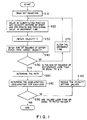
- Figure 1 is a flow chart illustrating the method of the present invention.
- the above coefficients a x , b x , c x , d x , a y , b y , c y , d y , a z , b z , c z , and d z can be obtained by substituting the position vector for the start point, the position vector for the end point, the velocity vector for the start point, the velocity vector for the end point, and a provisional movement time into the equations (step S20).
- step S50 determines whether the above differences have converged by checking whether or not the result is less than or equal to a minute constant value ⁇ , and if it is less than or equal to ⁇ , step S60 determines the path between the two points. At that point, velocity variations are at a minimum.
- step S50 If it is determined in step S50 that the differences have not converged, the movement time is altered in step S70 and the flow returns to step S20.
- step S80 If it is found as a result of obtaining the accelerations and decelerations required to realize the thus-obtained path (step S80) that these values exceed rated values (step S90), the velocity settings for the start and end points are reduced in step S100, and the flow returns to step S20 until a feasible path can be obtained.
- the above calculations can be performed by using a high-speed microprocessor or the like.
Description
- The present invention relates to a velocity-variation minimization control method for a robot and, in particular, to such a method suitable for application to a robot that performs painting or sealing work.
- In general, a robot that performs painting or sealing work is required to move along complex path both at high speed and smoothly.
- Therefore, such movements are realized by minutely specifying details of velocity and path, and such specification is done by teaching the specified velocity and specified path to a robot arm or limb at a fine pitch. In other words, a smooth path is obtained by detailed specifications for each of a large number of short distances or each of a large number of short periods of time.
- However, with this method, the algorithms required for teaching by detailed specification are complicated and hence the amount of calculation required increases, the necessary high velocities cannot be obtained, and velocity variations cannot be avoided.
- For that reason, smooth path control using high-order functions has been proposed.
- For example, Japanese Patent Laid-Open Number 62-72008 (1987) illustrates a fifth-order function method which can obtain a path in which variations with time in acceleration (second-order changes in velocity) are minimized, wherein (1) position at start and end points, (2) velocity vectors at start and end points, (3) acceleration vectors at start and end points, and (4) the time required to move between the two points, act as conditions for obtaining a path between two points.
- However, with this method, the user must take into consideration factors such as control based on the robot's abilities when specifying the time taken to move between the two points, which is a scalar quantity, and there is a problem that the path itself and the movement velocity can vary with the specified value of the movement time.
- From document EP-A1-0 319 587 a spline interpolation method has come to be known. In this known method, a spline curve is represented by a cubic equation. Four points, i.e., two points and two end points or three points and one end point are given to determine four coefficients of the cubic equation and to effect the interpolation. Since cubic equations are sequentially found for the remaining point sequences and the distance between the present position and the next point is repeatedly interpolated, no particular automatic programming apparatus is required for this known method. The interpolation can be effected even when a curve is to be determined by successively receiving the data.
- EP-A1-0 319 587 therefore discloses that a trace between two points is expressed by a cubic equation of time and that coefficients of the cubic equation are obtained from positions, velocity and moving time. Furthermore, the moving time is uniquely obtained from the moving distance all the length of chord between the two adjacent points.
- From document US-A-4,262,336 a multi-axis contouring control system has come to be known. According to this known system, a numerically control machine includes a first computer which stores command data for a path and derives sets of interpolatin point data from said command data for a plurality of points along the path. A second computer stores two sets of interpolation point data from said first computer and extrapolates a set of said stored interpolation point data by incrementing velocity with acceleration and position with velocity using a noncircular high order polynominal to produce a sequence of driver command signals. Hence, US-A-4,262,336 discloses an interpolation method for two points.
- This object is solved according to the invention by a velocity-variation minimization control method according to the features set out in independent claim 1. Dependent claim 2 exhibits further improvements of subject-matter of claim 1.
- There is provided a velocity-variation minimization control method for robot comprising: a step of substituting a position vector for a start point, a velocity vector for said start point, a position vector for an end point, a veleocity vector for said end point, and a provisional movement time into equations that express the position and velocity of said robot as cubic functions with respect to time, to obtain solutions for coefficients of said cubic functions; a step of obtaining a sum of squares of differences between a velocity obtained using said coefficients and a target velocity; and a step of using convergence calculations to obtain a value of said movement time that minimizes said sum of squares; a step of controlling said robot in such a manner that the far end of said robot follows a path based on said converged movement time.
- A position vector for a start point, a velocity vector for the start point, a position vector for an end point, a velocity vector for the end point, and a provisional movement time are substituted into equations that express the position and velocity of the robot as cubic functions with respect to time, to obtain solutions for coefficients of the cubic functions; a sum of squares of differences between a target velocity and a velocity obtained using these coefficients is obtained; and convergence calculations are used to obtain a value of the movement time that minimizes the sum of squares. By controlling the robot in such a manner that the far end of the robot follows a path based on the converged movement time, velocity variations can be minimized and a smooth path can be obtained.
- A patch can be obtained that has velocities approaching those of target velocities with minimized velocity variations, by simply substituting start point and end point vectors relating to position and velocity, and a provisional movement time. Therefore, a smooth robot movement can be realized, without the user having to specify a correct movement time.
- In the accompanying drawing,
- Figure 1 is a flow chart illustrating the method of the present invention.
- The present invention-will be described below in detail with reference to an embodiment whose flow chart is shown in Fig. 1. Positions on the path of the far end of the robot can be defined by the following cubic functions:


- In this case, the above coefficients ax, bx, cx, dx, ay, by, cy, dy, az, bz, cz, and dz can be obtained by substituting the position vector for the start point, the position vector for the end point, the velocity vector for the start point, the velocity vector for the end point, and a provisional movement time into the equations (step S20).
- Therefore, the velocity V of the end of the robot is obtained in step S30 as follows:


- If it is determined in step S50 that the differences have not converged, the movement time is altered in step S70 and the flow returns to step S20.
- Note that absolute values of the start and end point velocity vectors are specified by the user, but directions can be automatically determined with respect to the teaching point, so the user does not need to specify these values.
- If it is found as a result of obtaining the accelerations and decelerations required to realize the thus-obtained path (step S80) that these values exceed rated values (step S90), the velocity settings for the start and end points are reduced in step S100, and the flow returns to step S20 until a feasible path can be obtained.
- The above calculations can be performed by using a high-speed microprocessor or the like.
Claims (2)
- A velocity-variation minimization control method for robot comprising the steps of:a) preparing cubic equations expressing positions of an effector of a robot and quadratic equations expressing velocity of said effector,a1) said quadratic equations obtained by differentiating said cubic equations,a2) said cubic equations and said quadratic equations being functions with respect of time;b) obtaining solutions for coefficients of said equations by substitutingb1) a position vector for an operation start point,b2) a velocity vector for said operation start point,b3) a position vector for an operation end point,b4) a velocity vector for said operation end point, andb5) a provisional movement time for moving from said operation start point to said operation end pointinto said equations;c) obtaining a sum of squares of differences between a velocity obtained using said coefficients and a target velocity;d) performing convergence calculations to obtain a value of said movement time that minimizes said sum of squares; ande) controlling said robot by moving said effector along a path using converged movement time.
- A velocity-variation minimization control method for robot according to claim 1, further comprising the steps of:a) after performing said convergence calculations, obtaining acceleration and deceleration values for each axis of said robot in such a manner that the obtained path is realized;b) comparing the obtained acceleration and deceleration values with rated values;c) when said acceleration and deceleration values exceed said rated values, reducing velocity setting values; andd) returning to said step of obtaining solutions for coefficients by using said reduced velocity setting values.
Priority Applications (5)
| Application Number | Priority Date | Filing Date | Title |
|---|---|---|---|
| EP91105888A EP0507980B1 (en) | 1991-04-12 | 1991-04-12 | Velocity-variation minimization control method for robot |
| DE1991626960 DE69126960T2 (en) | 1991-04-12 | 1991-04-12 | Control method for minimizing the speed change of a robot |
| KR1019910005949A KR940010617B1 (en) | 1991-04-12 | 1991-04-13 | Minimizing control method of robot velocity change |
| US07/684,765 US5293460A (en) | 1991-04-12 | 1991-04-15 | Velocity-variation minimization control method for robot |
| CA002040459A CA2040459C (en) | 1991-04-12 | 1991-04-15 | Velocity-variation minimization control method for robot |
Applications Claiming Priority (4)
| Application Number | Priority Date | Filing Date | Title |
|---|---|---|---|
| EP91105888A EP0507980B1 (en) | 1991-04-12 | 1991-04-12 | Velocity-variation minimization control method for robot |
| KR1019910005949A KR940010617B1 (en) | 1991-04-12 | 1991-04-13 | Minimizing control method of robot velocity change |
| US07/684,765 US5293460A (en) | 1991-04-12 | 1991-04-15 | Velocity-variation minimization control method for robot |
| CA002040459A CA2040459C (en) | 1991-04-12 | 1991-04-15 | Velocity-variation minimization control method for robot |
Publications (2)
| Publication Number | Publication Date |
|---|---|
| EP0507980A1 EP0507980A1 (en) | 1992-10-14 |
| EP0507980B1 true EP0507980B1 (en) | 1997-07-23 |
Family
ID=27426846
Family Applications (1)
| Application Number | Title | Priority Date | Filing Date |
|---|---|---|---|
| EP91105888A Expired - Lifetime EP0507980B1 (en) | 1991-04-12 | 1991-04-12 | Velocity-variation minimization control method for robot |
Country Status (4)
| Country | Link |
|---|---|
| US (1) | US5293460A (en) |
| EP (1) | EP0507980B1 (en) |
| KR (1) | KR940010617B1 (en) |
| CA (1) | CA2040459C (en) |
Cited By (1)
| Publication number | Priority date | Publication date | Assignee | Title |
|---|---|---|---|---|
| WO1999028798A2 (en) * | 1997-12-02 | 1999-06-10 | Lacent Technologies Inc. | Gantry-mounted laser nozzle and method for controlling laser positioning |
Families Citing this family (4)
| Publication number | Priority date | Publication date | Assignee | Title |
|---|---|---|---|---|
| US5740327A (en) * | 1994-12-27 | 1998-04-14 | Nec Corporation | Method of and apparatus for robot tip trajectory control |
| DE102009049172B4 (en) * | 2009-10-13 | 2019-07-25 | Kuka Roboter Gmbh | Method and device for controlling a manipulator |
| IT1402158B1 (en) * | 2010-10-14 | 2013-08-28 | Agenzia Naz Per Le Nuove Tecnologie L En E Lo Sviluppo Economico Sostenibile Enea | DEVICE AND ITS PROCEDURE FOR THE CONTROL OF MANIPULATORS. |
| DE102014226914B4 (en) | 2014-12-23 | 2019-02-28 | Kuka Deutschland Gmbh | Override based predictive speed capping |
Citations (2)
| Publication number | Priority date | Publication date | Assignee | Title |
|---|---|---|---|---|
| US4262336A (en) * | 1979-04-27 | 1981-04-14 | Pritchard Eric K | Multi-axis contouring control system |
| EP0319587A1 (en) * | 1987-06-30 | 1989-06-14 | Fanuc Ltd. | Spline interpolation method |
Family Cites Families (5)
| Publication number | Priority date | Publication date | Assignee | Title |
|---|---|---|---|---|
| US4506335A (en) * | 1982-06-10 | 1985-03-19 | Cincinnati Milacron Inc. | Manipulator with controlled path motion |
| US4623971A (en) * | 1983-06-30 | 1986-11-18 | Cincinnati Milacron Inc. | Machine control with motor velocity constraint |
| US4772831A (en) * | 1986-11-20 | 1988-09-20 | Unimation, Inc. | Multiaxis robot control having improved continuous path operation |
| JPH079606B2 (en) * | 1988-09-19 | 1995-02-01 | 豊田工機株式会社 | Robot controller |
| JPH02256483A (en) * | 1989-03-29 | 1990-10-17 | Kobe Steel Ltd | Speed control device for industrial robot |
-
1991
- 1991-04-12 EP EP91105888A patent/EP0507980B1/en not_active Expired - Lifetime
- 1991-04-13 KR KR1019910005949A patent/KR940010617B1/en not_active IP Right Cessation
- 1991-04-15 CA CA002040459A patent/CA2040459C/en not_active Expired - Fee Related
- 1991-04-15 US US07/684,765 patent/US5293460A/en not_active Expired - Fee Related
Patent Citations (2)
| Publication number | Priority date | Publication date | Assignee | Title |
|---|---|---|---|---|
| US4262336A (en) * | 1979-04-27 | 1981-04-14 | Pritchard Eric K | Multi-axis contouring control system |
| EP0319587A1 (en) * | 1987-06-30 | 1989-06-14 | Fanuc Ltd. | Spline interpolation method |
Cited By (2)
| Publication number | Priority date | Publication date | Assignee | Title |
|---|---|---|---|---|
| WO1999028798A2 (en) * | 1997-12-02 | 1999-06-10 | Lacent Technologies Inc. | Gantry-mounted laser nozzle and method for controlling laser positioning |
| WO1999028798A3 (en) * | 1997-12-02 | 1999-10-14 | Lacent Technologies Inc | Gantry-mounted laser nozzle and method for controlling laser positioning |
Also Published As
| Publication number | Publication date |
|---|---|
| KR940010617B1 (en) | 1994-10-24 |
| CA2040459A1 (en) | 1992-10-16 |
| KR920019491A (en) | 1992-11-19 |
| US5293460A (en) | 1994-03-08 |
| CA2040459C (en) | 1997-01-21 |
| EP0507980A1 (en) | 1992-10-14 |
Similar Documents
| Publication | Publication Date | Title |
|---|---|---|
| KR920005251B1 (en) | Numerical controlling method for high dynamic processor | |
| US4623971A (en) | Machine control with motor velocity constraint | |
| US5396160A (en) | Method of real-time machine path planning from a math model | |
| EP0642893B1 (en) | Method for optimizing the motion of a multi-axis robot | |
| EP0098386B1 (en) | Manipulator with controlled path motion | |
| US4659265A (en) | Tool radius compensation method for numerically controlled apparatus | |
| EP0770941B1 (en) | Method and device for interpolating free-form surface | |
| GB2119965A (en) | Manipulator with adaptive velocity controlled path motion | |
| US5157315A (en) | Method of controlling robot movements | |
| EP0145967A2 (en) | Curvilinear interpolation system and method | |
| EP0380678B1 (en) | Method of controlling tool attitude of a robot | |
| US4879663A (en) | Method for determining points in space guiding the movement of a robot arm | |
| US5872894A (en) | Robot control apparatus and method eliminating any influence of motion in a preceding path and a recording medium storing the same | |
| US5373221A (en) | Method and system for estimating robot tool center point speed | |
| EP0528047B1 (en) | Method of controlling flowrate of sealing material in sealing by industrial robot | |
| EP0507980B1 (en) | Velocity-variation minimization control method for robot | |
| EP0490431B1 (en) | Machining apparatus | |
| US8024061B2 (en) | Method and device to generate position profile in motion controller | |
| US4980627A (en) | Numerically controlled apparatus | |
| EP0484551B1 (en) | Acceleration/deceleration time constant control system of robot | |
| EP0476381A1 (en) | Route interpolation method for robot | |
| EP0483756B1 (en) | Robot controlling method and apparatus | |
| US4926102A (en) | Involute interpolation method | |
| Yang et al. | On-line Cartesian trajectory control of mechanisms along complex curves | |
| JPH077302B2 (en) | Control Method for Minimizing Velocity Fluctuation of Robot |
Legal Events
| Date | Code | Title | Description |
|---|---|---|---|
| PUAI | Public reference made under article 153(3) epc to a published international application that has entered the european phase |
Free format text: ORIGINAL CODE: 0009012 |
|
| 17P | Request for examination filed |
Effective date: 19910422 |
|
| AK | Designated contracting states |
Kind code of ref document: A1 Designated state(s): DE FR GB NL |
|
| 17Q | First examination report despatched |
Effective date: 19940819 |
|
| GRAG | Despatch of communication of intention to grant |
Free format text: ORIGINAL CODE: EPIDOS AGRA |
|
| GRAH | Despatch of communication of intention to grant a patent |
Free format text: ORIGINAL CODE: EPIDOS IGRA |
|
| GRAH | Despatch of communication of intention to grant a patent |
Free format text: ORIGINAL CODE: EPIDOS IGRA |
|
| GRAA | (expected) grant |
Free format text: ORIGINAL CODE: 0009210 |
|
| AK | Designated contracting states |
Kind code of ref document: B1 Designated state(s): DE FR GB NL |
|
| PG25 | Lapsed in a contracting state [announced via postgrant information from national office to epo] |
Ref country code: NL Free format text: LAPSE BECAUSE OF FAILURE TO SUBMIT A TRANSLATION OF THE DESCRIPTION OR TO PAY THE FEE WITHIN THE PRESCRIBED TIME-LIMIT Effective date: 19970723 Ref country code: FR Effective date: 19970723 |
|
| REF | Corresponds to: |
Ref document number: 69126960 Country of ref document: DE Date of ref document: 19970904 |
|
| EN | Fr: translation not filed | ||
| NLV1 | Nl: lapsed or annulled due to failure to fulfill the requirements of art. 29p and 29m of the patents act | ||
| PLBE | No opposition filed within time limit |
Free format text: ORIGINAL CODE: 0009261 |
|
| STAA | Information on the status of an ep patent application or granted ep patent |
Free format text: STATUS: NO OPPOSITION FILED WITHIN TIME LIMIT |
|
| 26N | No opposition filed | ||
| PGFP | Annual fee paid to national office [announced via postgrant information from national office to epo] |
Ref country code: DE Payment date: 20010330 Year of fee payment: 11 |
|
| PGFP | Annual fee paid to national office [announced via postgrant information from national office to epo] |
Ref country code: GB Payment date: 20010411 Year of fee payment: 11 |
|
| REG | Reference to a national code |
Ref country code: GB Ref legal event code: IF02 |
|
| PG25 | Lapsed in a contracting state [announced via postgrant information from national office to epo] |
Ref country code: GB Free format text: LAPSE BECAUSE OF NON-PAYMENT OF DUE FEES Effective date: 20020412 |
|
| PG25 | Lapsed in a contracting state [announced via postgrant information from national office to epo] |
Ref country code: DE Free format text: LAPSE BECAUSE OF NON-PAYMENT OF DUE FEES Effective date: 20021101 |
|
| GBPC | Gb: european patent ceased through non-payment of renewal fee |
Effective date: 20020412 |