EP0507793B1 - Composting toilet - Google Patents
Composting toilet Download PDFInfo
- Publication number
- EP0507793B1 EP0507793B1 EP91900819A EP91900819A EP0507793B1 EP 0507793 B1 EP0507793 B1 EP 0507793B1 EP 91900819 A EP91900819 A EP 91900819A EP 91900819 A EP91900819 A EP 91900819A EP 0507793 B1 EP0507793 B1 EP 0507793B1
- Authority
- EP
- European Patent Office
- Prior art keywords
- composting
- drum
- toilet
- outer shell
- attached
- Prior art date
- Legal status (The legal status is an assumption and is not a legal conclusion. Google has not performed a legal analysis and makes no representation as to the accuracy of the status listed.)
- Expired - Lifetime
Links
Images

Classifications
-
- E—FIXED CONSTRUCTIONS
- E03—WATER SUPPLY; SEWERAGE
- E03D—WATER-CLOSETS OR URINALS WITH FLUSHING DEVICES; FLUSHING VALVES THEREFOR
- E03D5/00—Special constructions of flushing devices, e.g. closed flushing system
-
- A—HUMAN NECESSITIES
- A47—FURNITURE; DOMESTIC ARTICLES OR APPLIANCES; COFFEE MILLS; SPICE MILLS; SUCTION CLEANERS IN GENERAL
- A47K—SANITARY EQUIPMENT; ACCESSORIES THEREFOR, e.g. TOILET ACCESSORIES
- A47K11/00—Closets without flushing; Urinals without flushing; Chamber pots; Chairs with toilet conveniences or specially adapted for use with toilets
- A47K11/02—Dry closets, e.g. incinerator closets
-
- C—CHEMISTRY; METALLURGY
- C05—FERTILISERS; MANUFACTURE THEREOF
- C05F—ORGANIC FERTILISERS NOT COVERED BY SUBCLASSES C05B, C05C, e.g. FERTILISERS FROM WASTE OR REFUSE
- C05F3/00—Fertilisers from human or animal excrements, e.g. manure
- C05F3/04—Fertilisers from human or animal excrements, e.g. manure from human faecal masses
-
- Y—GENERAL TAGGING OF NEW TECHNOLOGICAL DEVELOPMENTS; GENERAL TAGGING OF CROSS-SECTIONAL TECHNOLOGIES SPANNING OVER SEVERAL SECTIONS OF THE IPC; TECHNICAL SUBJECTS COVERED BY FORMER USPC CROSS-REFERENCE ART COLLECTIONS [XRACs] AND DIGESTS
- Y02—TECHNOLOGIES OR APPLICATIONS FOR MITIGATION OR ADAPTATION AGAINST CLIMATE CHANGE
- Y02A—TECHNOLOGIES FOR ADAPTATION TO CLIMATE CHANGE
- Y02A40/00—Adaptation technologies in agriculture, forestry, livestock or agroalimentary production
- Y02A40/10—Adaptation technologies in agriculture, forestry, livestock or agroalimentary production in agriculture
- Y02A40/20—Fertilizers of biological origin, e.g. guano or fertilizers made from animal corpses
-
- Y—GENERAL TAGGING OF NEW TECHNOLOGICAL DEVELOPMENTS; GENERAL TAGGING OF CROSS-SECTIONAL TECHNOLOGIES SPANNING OVER SEVERAL SECTIONS OF THE IPC; TECHNICAL SUBJECTS COVERED BY FORMER USPC CROSS-REFERENCE ART COLLECTIONS [XRACs] AND DIGESTS
- Y02—TECHNOLOGIES OR APPLICATIONS FOR MITIGATION OR ADAPTATION AGAINST CLIMATE CHANGE
- Y02A—TECHNOLOGIES FOR ADAPTATION TO CLIMATE CHANGE
- Y02A50/00—TECHNOLOGIES FOR ADAPTATION TO CLIMATE CHANGE in human health protection, e.g. against extreme weather
- Y02A50/30—Against vector-borne diseases, e.g. mosquito-borne, fly-borne, tick-borne or waterborne diseases whose impact is exacerbated by climate change
-
- Y—GENERAL TAGGING OF NEW TECHNOLOGICAL DEVELOPMENTS; GENERAL TAGGING OF CROSS-SECTIONAL TECHNOLOGIES SPANNING OVER SEVERAL SECTIONS OF THE IPC; TECHNICAL SUBJECTS COVERED BY FORMER USPC CROSS-REFERENCE ART COLLECTIONS [XRACs] AND DIGESTS
- Y02—TECHNOLOGIES OR APPLICATIONS FOR MITIGATION OR ADAPTATION AGAINST CLIMATE CHANGE
- Y02P—CLIMATE CHANGE MITIGATION TECHNOLOGIES IN THE PRODUCTION OR PROCESSING OF GOODS
- Y02P20/00—Technologies relating to chemical industry
- Y02P20/141—Feedstock
- Y02P20/145—Feedstock the feedstock being materials of biological origin
-
- Y—GENERAL TAGGING OF NEW TECHNOLOGICAL DEVELOPMENTS; GENERAL TAGGING OF CROSS-SECTIONAL TECHNOLOGIES SPANNING OVER SEVERAL SECTIONS OF THE IPC; TECHNICAL SUBJECTS COVERED BY FORMER USPC CROSS-REFERENCE ART COLLECTIONS [XRACs] AND DIGESTS
- Y10—TECHNICAL SUBJECTS COVERED BY FORMER USPC
- Y10S—TECHNICAL SUBJECTS COVERED BY FORMER USPC CROSS-REFERENCE ART COLLECTIONS [XRACs] AND DIGESTS
- Y10S4/00—Baths, closets, sinks, and spittoons
- Y10S4/12—Aerobic decomposing toilet
-
- Y—GENERAL TAGGING OF NEW TECHNOLOGICAL DEVELOPMENTS; GENERAL TAGGING OF CROSS-SECTIONAL TECHNOLOGIES SPANNING OVER SEVERAL SECTIONS OF THE IPC; TECHNICAL SUBJECTS COVERED BY FORMER USPC CROSS-REFERENCE ART COLLECTIONS [XRACs] AND DIGESTS
- Y10—TECHNICAL SUBJECTS COVERED BY FORMER USPC
- Y10S—TECHNICAL SUBJECTS COVERED BY FORMER USPC CROSS-REFERENCE ART COLLECTIONS [XRACs] AND DIGESTS
- Y10S4/00—Baths, closets, sinks, and spittoons
- Y10S4/19—Liquid-solid separators
Definitions
- the present invention concerns a composting toilet comprising an outer shell with a toilet seat adapted to it, and a composting space adapted to the inside of the outer shell, said space being a rotatable drum into which solid toilet waste is collected and from which it is transferred into a collecting container, shaft or similar storage, and means for conducting liquids separately from solid waste, and a venting duct attached to the outer shell.
- the core of the compost actively produces heat, which is prevented from being lost with the help of a thick layer of the compost mass surrounding the core.
- the compost layer surrounding the compost core also helps slow excessive gas diffusion and thus is capable of reducing the cooling effect of the surrounding air.
- the superficial layer of the compost on one side continually receives the waste heat emitted by the core and, on the other side, it is cooled and dried by the freely moving air that surrounds the compost.
- CH-A-617 842 discloses a composting toilet having a toilet seat.
- distributor plate 8 solid waste does not fall directly onto the inside surface of the drum.
- a certain part of the urine remains on the distributor plate.
- the follower 9 pushes the solid excrement and the certain quantity of urine on the distributor plate into the composting tank 12.
- a portion of the urine frequently ends up into the bulk to be composted.
- the said document contemplates the use of fan-boosted ventilation and electrical heating to enhance composting.
- a preferred embodiment of the composting toilet in accordance with the invention is characterized by a recess adapted to its wall, said recess protruding into the drum, and by a discharge hole arranged to that wall of said recess which is opposingly facing the rotational direction of the drum, said hole permitting the discharge of the composted mass into a collecting container placed in said recess, and the container is removable via an opening access hatch placed in the outer shell of the toilet at the location of the recess.
- Another preferred embodiment of the composting toilet is characterized by having the toilet seat placed partially to the inside of the inlet opening of the drum.
- a further another preferred embodiment of the composting toilet in accordance with the invention is characterized in that the center of the drum bottom has a discharge hole, via which a portion of the compost mass contained in the drum is routed to a collecting container, shaft or similar storage outside the drum.
- the drum Due to the good thermal insulation of the drum in the composting toilet in accordance with the invention, the drum itself produces the necessary heat energy for the fermentation process, thus dispensing with the need for an external heat source.
- the generated heat also brings about the intermittently mandatory toilet ventilation, thus making forced ventilation unnecessary.
- the agitation in the drum provides for an immediate covering of the waste, minimization of support material need, equalization of moisture, oxygenation of the compost mass, and packing of the fermented mass into an easily removable collecting container.
- ventilation is cut off almost immediately after use, whereby air humidity and temperature can rapidly return back to optimum levels. Because liquids such as urine and washing water are not conducted to the composting space, moisture and consistency of the compost mass are retained at optimum levels.
- the fermented end product in the collecting container is completely odourless and homogeneous.
- the composting toilet comprises an outer shell 3, a toilet seat 4 and a composting space 2 adapted to the inside of the outer shell, said composting space being a rotatable drum.
- the longitudinal axis of the drum 2 is inclined from horizontal upward at an angle, preferredly approx. 30°.
- the drum 2 is pivotally mounted on bearings at a hub 22 to the outer shell 3, and its rotation is facilitated by support rolls 34, rotationally mounted on bearings to the outer shell, said rolls backing the drum 1 at its end of the inlet opening.
- the drum 2 is thermally insulated, whereby heat loss is avoided and the heat energy produced by the fermenting mass is retained in favour of the composting process, thus dispensing with the need for an external heat source.
- the drum 2 is rotated by means of a mechanical drive either manually with, for instance, a pedal, or by a motor.
- the inside of the drum 2 is equipped with fins 21, which promote the agitation of the fermenting mass.
- the fins 21 on the inside of the drum 2 are aligned either cross-directionally with or inclined to the rotational direction of the drum.
- the inlet opening of the drum 2 is closed by a partially or entirely thermally insulated stationary wall 6, which remains under the outer shell 3, there facing the compost mass.
- the wall 6 is provided with an inlet hole 62 and discharge hole 63 of the waste.
- a recess 61 protruding into the interior of the drum 2 is formed to the wall 6.
- a hole 63 through which the composted mass can be discharged by virtue of the rotation of the drum 2 into a collecting container 7 placed in the recess 61.
- the wall of the recess 61 opposingly facing the rotational direction of the drum 2 is inclined from horizontal upward at an angle, preferredly 45 ... 70°, whereby said wall prevents the particles of the compost mass pile from freely tumbling into the lower part of the drum 2 and from forming into poorly fermenting balls of the compost mass.
- the mouth section of the opening of the collecting container 7 is adapted tightly fitting to the hole 63 in the wall of the recess 61.
- the collecting container 7 can be removed via an opening access hatch 8 placed in the outer shell 3 at the location of the recess 61.
- the bottom of the recess 61 is provided with a retum hole 65 for recycling back to the drum 2 those compost mass clumps which may possibly fall over during the emptying of the collecting container 7.
- the hub 22 at the bottom of the drum 2 has a discharge hole 33, through which a portion of the compost mass contained in the drum 2 can be conducted to a collecting container, shaft or similar storage placed outside the drum 2.
- the underside of the toilet seat 4 is equipped with a transferrable member such as a shutter 5, by means of which liquids entering via the toilet seat 4 such as washing water and/or urine can be conducted past the composting space into a separate collecting container, treatment process or out from the toilet.
- a transferrable member such as a shutter 5
- Liquids are conducted via members 9 and 91 out from the composting toilet.
- the liquids separation means achieve excessive dampening of the compost mass, thereby avoiding disturbances to the fermenting process.
- the composting toilet can be connected to a water pipe for, e.g., the flushing of the interior of the toilet seat 4.
- the outer shell 3 has a ventilation duct 31 attached to it, complemented when necessary with a valve 32.
- the valve 32 makes it possible to open and close the toilet ventilation. Usually, the valve 32 is opened only during the use of the toilet. This arrangement minimizes heat losses.
- the ventilation air of the composting toilet enters the composting space 2 through the toilet seat via the hole 62 and exits the composting space 2 via ventilation hole 64 and ventilation duct 31 into the enviroment.
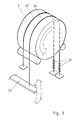
- Fig. 3 Diagrammatically illustrated in Fig. 3 is a rotating mechanism of the drum 2 designed for rotation of the drum 2 with the help of a pedal 26.
- One end of the ropes 23, 24 has attached a spring 25 whose other end is fixed to the frame of the composting toilet.
- One rope 24 is fixed at its other end to the pedal 26, while the other rope 23 is fixed to the frame of the composting toilet.
- the pedal 26 By depressing the pedal 26, the user can make the rope 24 to move in the direction indicated by the arrow, resulting in the rotation of the drum 2 in the same direction by means of the friction between the rope 24 and the drum 2.
- the frictional rotating means can be replaced by providing teeth to the outer circumference of the drum 2 and appropriate elements compatible with the toothing onto the rope.
- Such elements can be, e.g., cylindrical cog pins threaded on the rope.
- the rope 23 acts as ratchet preventing the drum from rotating backward by the weight of the contained mass.
Landscapes
- Public Health (AREA)
- Engineering & Computer Science (AREA)
- Health & Medical Sciences (AREA)
- Water Supply & Treatment (AREA)
- Hydrology & Water Resources (AREA)
- Life Sciences & Earth Sciences (AREA)
- Aviation & Aerospace Engineering (AREA)
- Chemical & Material Sciences (AREA)
- Organic Chemistry (AREA)
- Fertilizers (AREA)
- Non-Flushing Toilets (AREA)
- Credit Cards Or The Like (AREA)
- Printers Characterized By Their Purpose (AREA)
- Treatment Of Sludge (AREA)
- Pharmaceuticals Containing Other Organic And Inorganic Compounds (AREA)
Abstract
Description
- The present invention concerns a composting toilet comprising an outer shell with a toilet seat adapted to it, and a composting space adapted to the inside of the outer shell, said space being a rotatable drum into which solid toilet waste is collected and from which it is transferred into a collecting container, shaft or similar storage, and means for conducting liquids separately from solid waste, and a venting duct attached to the outer shell.
- During composting, the core of the compost actively produces heat, which is prevented from being lost with the help of a thick layer of the compost mass surrounding the core. The compost layer surrounding the compost core also helps slow excessive gas diffusion and thus is capable of reducing the cooling effect of the surrounding air. The superficial layer of the compost on one side continually receives the waste heat emitted by the core and, on the other side, it is cooled and dried by the freely moving air that surrounds the compost.
- Simulation of the conditions of a compost pile, particularly those of the superficial layer has been aimed at in such currently known composting toilets, especially in the electrically-powered types, that endeavour to achieve augmented composting. Such toilets use fan-boosted ventilation and electrical heating to enhance composting. These two basically contradictory functions mainly tend to cancel each other. The desired function of composting improvement is thereby hampered. Furthermore, the above-described toilets require externally supplied energy. The composting process is decelerated if the agitation of the compost mass is ineffective or totally lacking (/lacks totally). Resultingly, moisture and the support material may become unevenly dispersed in the bulk. Further, particles which differ in density from the average bulk, such as paper, may remain unmixed in the compost mass. Composting toilets of the above-described type are disclosed, i.a., the following publications: FI-54699, FI-854582, FI-2685/72 and FI-52709.
- The same drawbacks are also found in unheated containers of direct-composting toilets and in household waste composting equipment in general. The disadvantages of insufficient agitation are aimed to be compensated for by an over-dimensioned ventilation whose concomitant cooling effect impedes the composting process. This, unfortunately, compels to enlarge the equipment size, thereby leading to increased costs and more complicated toilet use and maintenance. Such a composting toilet is disclosed in, for instance, the Finnish patent FI-58487.
- CH-A-617 842 discloses a composting toilet having a toilet seat. When the toilet is in operation, the urine and excrement fall through the
seat portion 2 on to distributor plate 8 (= solid waste does not fall directly onto the inside surface of the drum). Depending on the position of inclination of thedistributor plate 8, a certain part of the urine remains on the distributor plate. During a pivoting movement thefollower 9 pushes the solid excrement and the certain quantity of urine on the distributor plate into the composting tank 12. In the toilet seat a portion of the urine frequently ends up into the bulk to be composted. The said document contemplates the use of fan-boosted ventilation and electrical heating to enhance composting. - It is the object of the invention to develop a composting toilet according to the preamble of
claim 1 such that it does not require externally supplied energy, but nevertheless provides optimum operation, particularly optimum composting. - This object is achieved by the characterizing features of
claim 1. - A preferred embodiment of the composting toilet in accordance with the invention is characterized by a recess adapted to its wall, said recess protruding into the drum, and by a discharge hole arranged to that wall of said recess which is opposingly facing the rotational direction of the drum, said hole permitting the discharge of the composted mass into a collecting container placed in said recess, and the container is removable via an opening access hatch placed in the outer shell of the toilet at the location of the recess.
- Another preferred embodiment of the composting toilet is characterized by having the toilet seat placed partially to the inside of the inlet opening of the drum.
- A further another preferred embodiment of the composting toilet in accordance with the invention is characterized in that the center of the drum bottom has a discharge hole, via which a portion of the compost mass contained in the drum is routed to a collecting container, shaft or similar storage outside the drum.
- Due to the good thermal insulation of the drum in the composting toilet in accordance with the invention, the drum itself produces the necessary heat energy for the fermentation process, thus dispensing with the need for an external heat source. The generated heat also brings about the intermittently mandatory toilet ventilation, thus making forced ventilation unnecessary. The agitation in the drum provides for an immediate covering of the waste, minimization of support material need, equalization of moisture, oxygenation of the compost mass, and packing of the fermented mass into an easily removable collecting container. In the composting toilet in accordance with the invention, ventilation is cut off almost immediately after use, whereby air humidity and temperature can rapidly return back to optimum levels. Because liquids such as urine and washing water are not conducted to the composting space, moisture and consistency of the compost mass are retained at optimum levels. The fermented end product in the collecting container is completely odourless and homogeneous.
- In the following, the invention will be examined in greater detail with the help of a preferred exemplifying embodiment with reference to the attached drawings, in which
- Fig. 1
- shows in a partially sectional side view a composting toilet in accordance with the invention,
- Fig. 2
- shows the composting toilet illustrated in Fig. 1 from the direction of
arrow 1, with the toilet seat (parts 4, 41...46 and 5) and the front part of theouter shell 3 removed, and - Fig. 3
- shows diagrammatically a rotating mechanism of the drum in the composting toilet seat in accordance with the invention.
- According to Figs. 1 and 2, the composting toilet comprises an
outer shell 3, a toilet seat 4 and acomposting space 2 adapted to the inside of the outer shell, said composting space being a rotatable drum. The longitudinal axis of thedrum 2 is inclined from horizontal upward at an angle, preferredly approx. 30°. Thedrum 2 is pivotally mounted on bearings at ahub 22 to theouter shell 3, and its rotation is facilitated bysupport rolls 34, rotationally mounted on bearings to the outer shell, said rolls backing thedrum 1 at its end of the inlet opening. Thedrum 2 is thermally insulated, whereby heat loss is avoided and the heat energy produced by the fermenting mass is retained in favour of the composting process, thus dispensing with the need for an external heat source. After use of the toilet, thedrum 2 is rotated by means of a mechanical drive either manually with, for instance, a pedal, or by a motor. The inside of thedrum 2 is equipped withfins 21, which promote the agitation of the fermenting mass. Thefins 21 on the inside of thedrum 2 are aligned either cross-directionally with or inclined to the rotational direction of the drum. - The inlet opening of the
drum 2 is closed by a partially or entirely thermally insulated stationary wall 6, which remains under theouter shell 3, there facing the compost mass. The wall 6 is provided with aninlet hole 62 anddischarge hole 63 of the waste. Arecess 61 protruding into the interior of thedrum 2 is formed to the wall 6. In practice the mass to be composted that is contained in thedrum 2 resides in the space delineated by thedrum 2 and therecess 61, said space having a volume of approximately half of the drum volume. Adapted to that wall of therecess 61 which is opposingly facing the rotational direction of thedrum 2 is ahole 63, through which the composted mass can be discharged by virtue of the rotation of thedrum 2 into acollecting container 7 placed in therecess 61. Furthermore, the wall of therecess 61 opposingly facing the rotational direction of thedrum 2 is inclined from horizontal upward at an angle, preferredly 45 ... 70°, whereby said wall prevents the particles of the compost mass pile from freely tumbling into the lower part of thedrum 2 and from forming into poorly fermenting balls of the compost mass. - The mouth section of the opening of the
collecting container 7 is adapted tightly fitting to thehole 63 in the wall of therecess 61. Thecollecting container 7 can be removed via anopening access hatch 8 placed in theouter shell 3 at the location of therecess 61. The bottom of therecess 61 is provided with aretum hole 65 for recycling back to thedrum 2 those compost mass clumps which may possibly fall over during the emptying of the collectingcontainer 7. - The
hub 22 at the bottom of thedrum 2 has adischarge hole 33, through which a portion of the compost mass contained in thedrum 2 can be conducted to a collecting container, shaft or similar storage placed outside thedrum 2. - The underside of the toilet seat 4 is equipped with a transferrable member such as a
shutter 5, by means of which liquids entering via the toilet seat 4 such as washing water and/or urine can be conducted past the composting space into a separate collecting container, treatment process or out from the toilet. The toilet seat 4, together with its associated liquids separation means 5, is disclosed in the parallel filed International Patent Application WO 91/09562 of the same applicant. - Liquids are conducted via
members - The composting toilet can be connected to a water pipe for, e.g., the flushing of the interior of the toilet seat 4.
- The
outer shell 3 has aventilation duct 31 attached to it, complemented when necessary with avalve 32. Thevalve 32 makes it possible to open and close the toilet ventilation. Usually, thevalve 32 is opened only during the use of the toilet. This arrangement minimizes heat losses. The ventilation air of the composting toilet enters thecomposting space 2 through the toilet seat via thehole 62 and exits thecomposting space 2 viaventilation hole 64 andventilation duct 31 into the enviroment. - Diagrammatically illustrated in Fig. 3 is a rotating mechanism of the
drum 2 designed for rotation of thedrum 2 with the help of apedal 26. There are tworopes drum 2. One end of theropes spring 25 whose other end is fixed to the frame of the composting toilet. Onerope 24 is fixed at its other end to thepedal 26, while theother rope 23 is fixed to the frame of the composting toilet. By depressing the pedal 26, the user can make therope 24 to move in the direction indicated by the arrow, resulting in the rotation of thedrum 2 in the same direction by means of the friction between therope 24 and thedrum 2. - The frictional rotating means can be replaced by providing teeth to the outer circumference of the
drum 2 and appropriate elements compatible with the toothing onto the rope. Such elements can be, e.g., cylindrical cog pins threaded on the rope. Therope 23 acts as ratchet preventing the drum from rotating backward by the weight of the contained mass. - For those versed in the art, it is obvious that the invention is not limited to the exemplifying embodiments described above; by contrast, the invention can be varied within the claims disclosed herein.
Claims (9)
- A composting toilet (1) comprising- an outer shell (3) with an attached toilet seat (4) and a composting space situated in the interior of the outer shell (3), into which composting space solid waste is collected in a collecting container, shaft or similar storage,- means (5) for conducting liquids separately from solid waste, and- a ventilation duct (31) attached to the outer shell (3),characterized in that- the composting space is a rotatable, thermally insulated drum (2) at the inlet opening of which there is attached a stationary wall (6) having an inlet hole (62) and a ventilation hole (64),- the toilet seat (4) with the liquid separation means is attached to the outer shell (3) at the location of the stationary wall (6),- the composting space is inclined from the horizontal upwards towards the side of stationary wall (6), and- the toilet seat (4) is located partially inside the inlet opening of the composting space, allowing solid waste to enter via the toilet seat (4) and to fall through the inlet hole (62) of the stationary wall (6) directly onto the inside surface of the composting space.
- A composting toilet as claimed in claim 1, characterized in that to the wall (6) is formed a recess (61) protruding into the drum (2) and the wall of said recess (61) which is opposingly facing the rotational direction of the drum (2) is provided with a discharge hole (63), said hole permitting the discharge of the composted mass into a collecting container (7) placed in said recess (61), said container being removable via an opening access hatch (8) placed in the outer shell (3) of the toilet at the location of the recess.
- A composting toilet as claimed in claim 1 , characterized in that the hub (22) at the bottom of the drum (2) has a discharge hole (33), through which the compost mass can discharge to a collecting container, shaft or similar storage placed outside the drum 2.
- A composting toilet as claimed in claim 2, characterized in that the bottom of the recess (61) is provided with a return hole (65) for the recycling of compost mass clumps, which may possibly fall over during the emptying of the collecting container (7), back to the drum (2).
- A composting toilet as claimed in any of the foregoing claims, characterized in that the inside of the drum (2) is equipped with fins (21).
- A composting toilet as claimed in any of the foregoing claims, characterized in that the rotating mechanism of the drum (2) comprises two ropes (23, 24), whose one ends are attached by means of springs (25) to the outer shell (3) and that the other end of the rope (24) is attached to a pedal (26), while the other end of the rope (23) is fixed immobile.
- A composting toilet as claimed in claim 6, characterized in that the ropes (23, 24) are adapted to pass over the circumference of the drum (2), said ropes being adapted to include one or several elements appropriately compatible with the toothing formed onto the circumference of the drum (2)
- A composting toilet as claimed in any of the foregoing claims, characterized in that the ventilation duct (31) is provided with a valve (32).
- A composting toilet as claimed in any of the foregoing claims, characterized in that it has a water pipe attached to it.
Applications Claiming Priority (3)
| Application Number | Priority Date | Filing Date | Title |
|---|---|---|---|
| FI896363 | 1989-12-29 | ||
| FI896363A FI89259C (en) | 1989-12-29 | 1989-12-29 | Förmultningstoalett |
| PCT/FI1990/000308 WO1991009819A1 (en) | 1989-12-29 | 1990-12-20 | Composting toilet |
Publications (2)
| Publication Number | Publication Date |
|---|---|
| EP0507793A1 EP0507793A1 (en) | 1992-10-14 |
| EP0507793B1 true EP0507793B1 (en) | 1997-10-08 |
Family
ID=8529629
Family Applications (1)
| Application Number | Title | Priority Date | Filing Date |
|---|---|---|---|
| EP91900819A Expired - Lifetime EP0507793B1 (en) | 1989-12-29 | 1990-12-20 | Composting toilet |
Country Status (10)
| Country | Link |
|---|---|
| US (1) | US5303431A (en) |
| EP (1) | EP0507793B1 (en) |
| JP (1) | JPH05504274A (en) |
| AT (1) | ATE159008T1 (en) |
| AU (1) | AU651956B2 (en) |
| CA (1) | CA2072574A1 (en) |
| DE (1) | DE69031568T2 (en) |
| FI (1) | FI89259C (en) |
| NO (1) | NO301323B1 (en) |
| WO (1) | WO1991009819A1 (en) |
Families Citing this family (12)
| Publication number | Priority date | Publication date | Assignee | Title |
|---|---|---|---|---|
| FR2666732B1 (en) * | 1990-09-19 | 1994-08-05 | Centre Experim Document Energies | DRY ROTATING COMPOST TOILET. |
| USD354340S (en) | 1993-03-11 | 1995-01-10 | Henric Sundberg | Composting toilet |
| US5345620A (en) * | 1993-03-26 | 1994-09-13 | Henric Sundberg | Composting toilet |
| SE9902446D0 (en) * | 1999-06-23 | 1999-06-23 | Gun Birgit Soederberg | Drainage systems |
| JPWO2006123411A1 (en) * | 2005-05-18 | 2008-12-25 | 株式会社大田鋳造所 | Simple toilet |
| FI20065512A7 (en) * | 2006-08-15 | 2008-02-16 | Biolan Oy | Composting device and method for composting waste |
| US9247852B2 (en) | 2010-11-22 | 2016-02-02 | Geoffrey Trott | Composting toilet |
| DE102014012311A1 (en) * | 2014-08-16 | 2016-02-18 | 3P Technik Filtersysteme Gmbh | Dry toilet facility |
| DK3420225T3 (en) | 2016-02-23 | 2020-03-16 | Lm Wind Power Int Tech Ii Aps | Wing deflection monitoring system |
| US10676907B2 (en) * | 2017-06-19 | 2020-06-09 | David Jay MAST | Organic waste treatment process and device |
| US11492792B2 (en) | 2020-02-03 | 2022-11-08 | Wish for WASH, LLC | Modular toilet systems and methods |
| WO2021158934A1 (en) * | 2020-02-06 | 2021-08-12 | Medal Technologies, LLC | Compact composting toilet |
Family Cites Families (12)
| Publication number | Priority date | Publication date | Assignee | Title |
|---|---|---|---|---|
| US1383295A (en) * | 1919-08-27 | 1921-07-05 | Said Gausewitz | Closet |
| US3683425A (en) * | 1970-10-07 | 1972-08-15 | Leroy Patterson | Combustion toilet |
| SE368699C (en) * | 1972-09-19 | 1975-12-01 | Gustavsbergs Fabriker Ab | DEVICE FOR TOILETS INTENDED FOR BIOLOGICAL DECOMPOSITION OF HUMAN EXCREMATION. |
| SE396068B (en) * | 1975-12-29 | 1977-09-05 | Metz Ilmar | RECOVERY TOILET |
| FI52709C (en) * | 1976-05-06 | 1977-11-10 | Upo Oy | Biological dry toilet. |
| NO793564L (en) * | 1978-11-06 | 1980-05-07 | Inventor Invest Ab | DECOMPOSITION CONTAINER, SPECIAL DECOMPOSITION TOILET |
| FI58487C (en) * | 1979-03-14 | 1981-02-10 | Tapio Raita | compost |
| FI68802C (en) * | 1983-11-16 | 1985-11-11 | Jarmo Louvo | ANORDNING FOER BEHANDLING AV BIOLOGISKT AVFALL GENOM KOMPOSTERING |
| NO841325L (en) * | 1984-04-04 | 1985-10-07 | Terje Erik Ogngard | APPLICATION BY THE PREDICTION TOILET. |
| SE441195B (en) * | 1984-04-10 | 1985-09-16 | Moelnlycke Ab | DEVICE FOR SHAPING A FIBER COAT |
| FI78897C (en) * | 1988-09-01 | 1989-10-10 | Matti Juhani Yloesjoki | Composters for toilet and kitchen waste |
| FR2666732B1 (en) * | 1990-09-19 | 1994-08-05 | Centre Experim Document Energies | DRY ROTATING COMPOST TOILET. |
-
1989
- 1989-12-29 FI FI896363A patent/FI89259C/en not_active IP Right Cessation
-
1990
- 1990-12-20 JP JP3501273A patent/JPH05504274A/en active Pending
- 1990-12-20 US US07/917,021 patent/US5303431A/en not_active Expired - Fee Related
- 1990-12-20 AT AT91900819T patent/ATE159008T1/en not_active IP Right Cessation
- 1990-12-20 WO PCT/FI1990/000308 patent/WO1991009819A1/en not_active Ceased
- 1990-12-20 AU AU69521/91A patent/AU651956B2/en not_active Ceased
- 1990-12-20 DE DE69031568T patent/DE69031568T2/en not_active Expired - Fee Related
- 1990-12-20 EP EP91900819A patent/EP0507793B1/en not_active Expired - Lifetime
- 1990-12-20 CA CA002072574A patent/CA2072574A1/en not_active Abandoned
-
1992
- 1992-06-26 NO NO922549A patent/NO301323B1/en unknown
Also Published As
| Publication number | Publication date |
|---|---|
| NO922549L (en) | 1992-08-07 |
| US5303431A (en) | 1994-04-19 |
| DE69031568D1 (en) | 1997-11-13 |
| JPH05504274A (en) | 1993-07-08 |
| ATE159008T1 (en) | 1997-10-15 |
| FI896363A0 (en) | 1989-12-29 |
| NO922549D0 (en) | 1992-06-26 |
| NO301323B1 (en) | 1997-10-13 |
| AU651956B2 (en) | 1994-08-11 |
| FI89259B (en) | 1993-05-31 |
| FI89259C (en) | 1993-09-10 |
| WO1991009819A1 (en) | 1991-07-11 |
| CA2072574A1 (en) | 1991-06-30 |
| FI896363L (en) | 1991-06-30 |
| DE69031568T2 (en) | 1998-02-12 |
| AU6952191A (en) | 1991-07-24 |
| EP0507793A1 (en) | 1992-10-14 |
Similar Documents
| Publication | Publication Date | Title |
|---|---|---|
| AU651956B2 (en) | Composting toilet | |
| US4152974A (en) | Hot air corn popper | |
| US4633535A (en) | Apparatus for treating biological waste by means of composting | |
| US5622140A (en) | Pet litter box and screening apparatus | |
| US5171690A (en) | Composting device for toilet and kitchen waste | |
| CA2119792C (en) | Composting toilet | |
| EP1115678B1 (en) | Method and machine for decomposing organic waste | |
| KR102299190B1 (en) | Pet food feeding equipment | |
| RU2037478C1 (en) | Compost lavatory | |
| US5289595A (en) | Dry-operated rotary composting toilet | |
| US3648662A (en) | Ventilating system for livestock feeders | |
| JP2004181325A (en) | Garbage processing machine | |
| KR101240760B1 (en) | A food trash control device | |
| KR960016786B1 (en) | Fertilizer apparatus | |
| JP2003275712A (en) | Garbage processing equipment | |
| EP0176548A1 (en) | Device on a biological toilet | |
| JP2599041Y2 (en) | Garbage processing machine | |
| JPH08338687A (en) | Garbage processing machine | |
| CN217017934U (en) | Small-size kitchen garbage decrement equipment | |
| JPH08131369A (en) | Incineration waste discharge device in incinerator | |
| FI72309C (en) | FOERFARANDE FOER BEHANDLING AV BIOLOGISKT AVFALL MED HJAELP AV KOMPOSTERING. | |
| JP3178329U (en) | Biomass toilet | |
| JPS6355976B2 (en) | ||
| JP2001047012A (en) | Garbage disposal equipment | |
| CA2329254A1 (en) | Drying apparatus |
Legal Events
| Date | Code | Title | Description |
|---|---|---|---|
| PUAI | Public reference made under article 153(3) epc to a published international application that has entered the european phase |
Free format text: ORIGINAL CODE: 0009012 |
|
| 17P | Request for examination filed |
Effective date: 19920728 |
|
| AK | Designated contracting states |
Kind code of ref document: A1 Designated state(s): AT BE CH DE DK ES FR GB IT LI NL SE |
|
| 17Q | First examination report despatched |
Effective date: 19941206 |
|
| GRAG | Despatch of communication of intention to grant |
Free format text: ORIGINAL CODE: EPIDOS AGRA |
|
| GRAH | Despatch of communication of intention to grant a patent |
Free format text: ORIGINAL CODE: EPIDOS IGRA |
|
| GRAH | Despatch of communication of intention to grant a patent |
Free format text: ORIGINAL CODE: EPIDOS IGRA |
|
| GRAA | (expected) grant |
Free format text: ORIGINAL CODE: 0009210 |
|
| AK | Designated contracting states |
Kind code of ref document: B1 Designated state(s): AT BE CH DE DK ES FR GB IT LI NL SE |
|
| PG25 | Lapsed in a contracting state [announced via postgrant information from national office to epo] |
Ref country code: IT Free format text: LAPSE BECAUSE OF FAILURE TO SUBMIT A TRANSLATION OF THE DESCRIPTION OR TO PAY THE FEE WITHIN THE PRESCRIBED TIME-LIMIT;WARNING: LAPSES OF ITALIAN PATENTS WITH EFFECTIVE DATE BEFORE 2007 MAY HAVE OCCURRED AT ANY TIME BEFORE 2007. THE CORRECT EFFECTIVE DATE MAY BE DIFFERENT FROM THE ONE RECORDED. Effective date: 19971008 Ref country code: ES Free format text: THE PATENT HAS BEEN ANNULLED BY A DECISION OF A NATIONAL AUTHORITY Effective date: 19971008 Ref country code: FR Free format text: LAPSE BECAUSE OF FAILURE TO SUBMIT A TRANSLATION OF THE DESCRIPTION OR TO PAY THE FEE WITHIN THE PRESCRIBED TIME-LIMIT Effective date: 19971008 Ref country code: NL Free format text: LAPSE BECAUSE OF FAILURE TO SUBMIT A TRANSLATION OF THE DESCRIPTION OR TO PAY THE FEE WITHIN THE PRESCRIBED TIME-LIMIT Effective date: 19971008 Ref country code: LI Free format text: LAPSE BECAUSE OF FAILURE TO SUBMIT A TRANSLATION OF THE DESCRIPTION OR TO PAY THE FEE WITHIN THE PRESCRIBED TIME-LIMIT Effective date: 19971008 Ref country code: CH Free format text: LAPSE BECAUSE OF FAILURE TO SUBMIT A TRANSLATION OF THE DESCRIPTION OR TO PAY THE FEE WITHIN THE PRESCRIBED TIME-LIMIT Effective date: 19971008 Ref country code: DK Free format text: LAPSE BECAUSE OF NON-PAYMENT OF DUE FEES Effective date: 19971008 Ref country code: AT Free format text: LAPSE BECAUSE OF FAILURE TO SUBMIT A TRANSLATION OF THE DESCRIPTION OR TO PAY THE FEE WITHIN THE PRESCRIBED TIME-LIMIT Effective date: 19971008 Ref country code: BE Free format text: LAPSE BECAUSE OF FAILURE TO SUBMIT A TRANSLATION OF THE DESCRIPTION OR TO PAY THE FEE WITHIN THE PRESCRIBED TIME-LIMIT Effective date: 19971008 |
|
| REF | Corresponds to: |
Ref document number: 159008 Country of ref document: AT Date of ref document: 19971015 Kind code of ref document: T |
|
| REG | Reference to a national code |
Ref country code: CH Ref legal event code: EP |
|
| REF | Corresponds to: |
Ref document number: 69031568 Country of ref document: DE Date of ref document: 19971113 |
|
| PGFP | Annual fee paid to national office [announced via postgrant information from national office to epo] |
Ref country code: SE Payment date: 19980102 Year of fee payment: 8 |
|
| PG25 | Lapsed in a contracting state [announced via postgrant information from national office to epo] |
Ref country code: GB Free format text: LAPSE BECAUSE OF NON-PAYMENT OF DUE FEES Effective date: 19980108 |
|
| NLV1 | Nl: lapsed or annulled due to failure to fulfill the requirements of art. 29p and 29m of the patents act | ||
| EN | Fr: translation not filed | ||
| REG | Reference to a national code |
Ref country code: CH Ref legal event code: PL |
|
| PLBE | No opposition filed within time limit |
Free format text: ORIGINAL CODE: 0009261 |
|
| STAA | Information on the status of an ep patent application or granted ep patent |
Free format text: STATUS: NO OPPOSITION FILED WITHIN TIME LIMIT |
|
| GBPC | Gb: european patent ceased through non-payment of renewal fee |
Effective date: 19980108 |
|
| PG25 | Lapsed in a contracting state [announced via postgrant information from national office to epo] |
Ref country code: DE Free format text: LAPSE BECAUSE OF NON-PAYMENT OF DUE FEES Effective date: 19980901 |
|
| 26N | No opposition filed | ||
| PG25 | Lapsed in a contracting state [announced via postgrant information from national office to epo] |
Ref country code: SE Free format text: LAPSE BECAUSE OF NON-PAYMENT OF DUE FEES Effective date: 19981221 |