EP0507618A2 - Verfahren und Vorrichtung zum Zuführen von Abschreckflüssigkeiten für Rohre - Google Patents
Verfahren und Vorrichtung zum Zuführen von Abschreckflüssigkeiten für Rohre Download PDFInfo
- Publication number
- EP0507618A2 EP0507618A2 EP92302980A EP92302980A EP0507618A2 EP 0507618 A2 EP0507618 A2 EP 0507618A2 EP 92302980 A EP92302980 A EP 92302980A EP 92302980 A EP92302980 A EP 92302980A EP 0507618 A2 EP0507618 A2 EP 0507618A2
- Authority
- EP
- European Patent Office
- Prior art keywords
- lance
- head
- pipe
- tail
- pipes
- Prior art date
- Legal status (The legal status is an assumption and is not a legal conclusion. Google has not performed a legal analysis and makes no representation as to the accuracy of the status listed.)
- Withdrawn
Links
Images
Classifications
-
- C—CHEMISTRY; METALLURGY
- C21—METALLURGY OF IRON
- C21D—MODIFYING THE PHYSICAL STRUCTURE OF FERROUS METALS; GENERAL DEVICES FOR HEAT TREATMENT OF FERROUS OR NON-FERROUS METALS OR ALLOYS; MAKING METAL MALLEABLE, e.g. BY DECARBURISATION OR TEMPERING
- C21D9/00—Heat treatment, e.g. annealing, hardening, quenching or tempering, adapted for particular articles; Furnaces therefor
- C21D9/08—Heat treatment, e.g. annealing, hardening, quenching or tempering, adapted for particular articles; Furnaces therefor for tubular bodies or pipes
- C21D9/085—Cooling or quenching
Definitions
- This invention relates to applying quench liquid to pipes, and more particularly to a method of and apparatus for applying quench liquid to pipes including facility for enabling transportation of pipes, e.g. low alloy steel pipes, through a quenching station whereby they may be hardened by cooling them from austenitising temperature (i.e. > A 3 ).
- This invention provides, according to one aspect, a method of applying quench liquid to pipe comprising transporting pipes sequentially and longitudinally through a quenching station having a tubular lance, a tail end of which is coupled to a liquid source and the other end of which is provided with a head from which the liquid is projected laterally in a series of jets, characterised in that the lance is supported at the tail and at at least one intermediate position along its length whilst the leading end of the pipe passes onto the lance over the head thereof with the quench liquid on; the lance is then additionally supported at the head when the trailing end of the pipe has cleared the head with the quench liquid on; the or each intermediate support is displaced to permit passage of the pipe therepast; the tail coupling is released and displaced with the quench liquid off to permit the passage of the pipe therepast and; the tail coupling and the or each intermediate support is reinstated when the trailing end of the pipe has cleared the tail of the lance and the head support is displaced to accommodate the next pipe.
- This invention provides according to another aspect, apparatus for applying quench liquid to pipes comprising a quenching station and means of transporting pipes therethrough sequentially and longitudinally, the quenching station having a tubular lance, a tail end of which is arranged to be connected to a liquid source coupling and the other end of which carries a head from which the quench liquid is projected laterally, characterised by the provision of a displaceable support at the tail of the lance, at least one displaceable support at an intermediate position along the lance length, and a displaceable support at the head of the lance, together with a control valve associated with the liquid source coupling, and that the liquid source coupling is displaceable; the arrangement being such that in use the lance is supported at the tail and at at least one intermediate position along its length whilst the leading end of a pipe passes onto the lance over the head thereof with the control valve open, the lance is supported at its head when the trailing end of the pipe has cleared the head with the control valve open, and the or each intermediate support is
- the pipe is rotated as it progresses, thus describing a helical path.
- the quench liquid may be water and as mentioned above, the interior pipe quenching from the lance may be accompanied by exterior quenching at the same station.
- the invention provides a means by which an internal cooling facility may be added to an existing external cooling facility without the need for any additional quench water capacity and without any significant increase in the space required to install and operate the equipment.
- the invention may be utilised to produce a controlled hardness profile across the pipe wall thickness, with increasing hardness at the bore; alternatively, when used in conjunction with external quenching the invention can be utilised to achieve uniform through wall hardness.
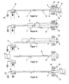
- a pipe 2 heated to austentising temperature is advanced at constant speed in a helical manner by a pipe-conveying apparatus (not shown) and passes over a guide cone 3 mounted in front of a head 4 of a tubular lance 5.
- the guide cone may be rotable on the lance with the oncoming pipe.
- an intermediate retractable support arm 6 Adjacent to the head of the lance, an intermediate retractable support arm 6 holds the lance 5 in a position approximating to the axis of the approaching pipe 2. Also supporting the lance 5 at this time is a second intermediate support arm 7 and a rear or tail end support bracket 8.
- the lance rear support bracket positions the lance 5 on the same axis as a sealing coupling 9 through which high pressure water is supplied to the lance 5 via control valve 10.
- Water is likewise supplied to external quench rings 12.
- a head support comprising a pair of arms 13, shown in the retracted mode, is sited adjacent these quench rings and immediately behind the guide cone of the lance.
- the pipe is shown to have advanced almost completely through the quench head, the intermediate support arms 6 and 7 having been retracted to permit this whilst the pair of head support arms 13 now close into engagement with the head 4 immediately behind the guide cone 3.
- the purpose of the upper arm at this site is to prevent any tendency for the lance head to lift off the lower arm as the pipe and guide cone 3 rotate, which might otherwise occur.
- valve 10 is closed and the sealing head 9 is disconnected from the lance 5 and retracted into the position shown.
- the lance 5 since it is now only supported adjacent the head, inclines into the attitude shown and is brought back into axial alignment by the action of intermediate support arms 6 and 7 which resume their former positions as the pipe trailing end moves clear of them.
- FIG 1d shows this situation with the pipe now clear of the whole lance which is supported on support arms 6 and 7 and held by the head support 13.
- the speed at which the pipe 2 is conveyed may be increased so as to increase the rate of operation of the equipment, the delay between processing successive pipes being minimised.
- the external cooling water rings 12, the intermediate support arms 6/7 and the head support arms may all be conveniently fixed to a common framework such that they may all be set to accommodate different pipe diameters by a simple height adjustment through an arrangement of interconnected jacks.
Landscapes
- Chemical & Material Sciences (AREA)
- Engineering & Computer Science (AREA)
- Physics & Mathematics (AREA)
- Thermal Sciences (AREA)
- Crystallography & Structural Chemistry (AREA)
- Mechanical Engineering (AREA)
- Materials Engineering (AREA)
- Metallurgy (AREA)
- Organic Chemistry (AREA)
- Heat Treatment Of Articles (AREA)
Applications Claiming Priority (2)
| Application Number | Priority Date | Filing Date | Title |
|---|---|---|---|
| GB9106975 | 1991-04-03 | ||
| GB919106975A GB9106975D0 (en) | 1991-04-03 | 1991-04-03 | Method of and apparatus for applying quench liquid to pipes |
Publications (2)
| Publication Number | Publication Date |
|---|---|
| EP0507618A2 true EP0507618A2 (de) | 1992-10-07 |
| EP0507618A3 EP0507618A3 (en) | 1993-10-06 |
Family
ID=10692579
Family Applications (1)
| Application Number | Title | Priority Date | Filing Date |
|---|---|---|---|
| EP19920302980 Withdrawn EP0507618A3 (en) | 1991-04-03 | 1992-04-03 | Method of and apparatus for applying quench liquids to pipes |
Country Status (2)
| Country | Link |
|---|---|
| EP (1) | EP0507618A3 (de) |
| GB (1) | GB9106975D0 (de) |
Family Cites Families (3)
| Publication number | Priority date | Publication date | Assignee | Title |
|---|---|---|---|---|
| US3294599A (en) * | 1963-07-30 | 1966-12-27 | Smith Corp A O | Method and apparatus for heat treating low carbon steel |
| DE2349913B1 (de) * | 1973-10-02 | 1975-04-10 | Mannesmann Roehren Werke Ag | Vorrichtung und Verfahren zum Abschreckhaerten von Rohren |
| DE2432923C2 (de) * | 1974-07-05 | 1976-08-05 | Mannesmann Ag | Verfahren und Vorrichtung zum kontinuierlichen Härten, insbesondere dickwandiger Stahlrohre |
-
1991
- 1991-04-03 GB GB919106975A patent/GB9106975D0/en active Pending
-
1992
- 1992-04-03 EP EP19920302980 patent/EP0507618A3/en not_active Withdrawn
Also Published As
| Publication number | Publication date |
|---|---|
| GB9106975D0 (en) | 1991-05-22 |
| EP0507618A3 (en) | 1993-10-06 |
Similar Documents
| Publication | Publication Date | Title |
|---|---|---|
| DE102013007737B4 (de) | Beschichtungsvorrichtung zum thermischen Beschichten | |
| DE102013014086B3 (de) | Vorrichtung zum Außentrocknen von Flaschen | |
| US4137928A (en) | Apparatus for cleaning the interior of tubes | |
| EP0576398B1 (de) | Verfahren, Vorrichtung und Maschine zum Reinigen von einseitig offenen Behältnissen | |
| EP3012088B1 (de) | Vorrichtung und verfahren zum transportieren von kunststoffvorformlingen mit zweifachem teilungsverzug | |
| US3392565A (en) | Manufacture of seamless tubing | |
| EP4335296A2 (de) | Anordnung und verfahren zur geflügelförderung | |
| US3958796A (en) | Quench-hardening of pipes | |
| EP0507618A2 (de) | Verfahren und Vorrichtung zum Zuführen von Abschreckflüssigkeiten für Rohre | |
| GB1228234A (de) | ||
| EP0805771B1 (de) | Vorrichtung zum ausleiten von einzelnen oder mehreren rotationssymmetrischen behältern aus einem unter staudruck geförderten strom der rotationssymmetrischen behälter und zylinder mit gesteuert ausfahrbarem kolben | |
| US3186655A (en) | Method and apparatus for handling coils of strip | |
| US2560058A (en) | Tube and rod production | |
| US5809823A (en) | Method and apparatus for feeding a tubular workpiece into a drawing unit | |
| EP3878626A1 (de) | Vorrichtung und verfahren zum behandeln von kunststoffvorformlingen mit integrierter vorformlingzuführung | |
| GB2263537A (en) | Piercing a taphole for a shaft furnace | |
| US2959847A (en) | Apparatus for unloading rings from a mandrel | |
| US2492876A (en) | Drawbench | |
| US4417928A (en) | Inside-outside tube quenching method | |
| GB2263536A (en) | Piercing a taphole for a shaft furnace | |
| EP0849010B1 (de) | Verfahren und Vorrichtung zum Kaltwalzen von Rohren und Stangen | |
| US5312293A (en) | Head washing apparatus | |
| WO1985000023A1 (en) | Pipe deforming method and apparatus | |
| US3358490A (en) | Steadier for mandrel bar and tube shell | |
| JPH11500960A (ja) | ダイカスト機器を潤滑し且つ掃除するための装置及び方法 |
Legal Events
| Date | Code | Title | Description |
|---|---|---|---|
| PUAI | Public reference made under article 153(3) epc to a published international application that has entered the european phase |
Free format text: ORIGINAL CODE: 0009012 |
|
| AK | Designated contracting states |
Kind code of ref document: A2 Designated state(s): AT BE CH DE DK ES FR GB GR IT LI LU MC NL PT SE |
|
| PUAL | Search report despatched |
Free format text: ORIGINAL CODE: 0009013 |
|
| AK | Designated contracting states |
Kind code of ref document: A3 Designated state(s): AT BE CH DE DK ES FR GB GR IT LI LU MC NL PT SE |
|
| 17P | Request for examination filed |
Effective date: 19940325 |
|
| RAP1 | Party data changed (applicant data changed or rights of an application transferred) |
Owner name: TUBULAR INDUSTRIES SCOTLAND LIMITED |
|
| STAA | Information on the status of an ep patent application or granted ep patent |
Free format text: STATUS: THE APPLICATION IS DEEMED TO BE WITHDRAWN |
|
| 18D | Application deemed to be withdrawn |
Effective date: 19961104 |