EP0507544B1 - Abdichtungshülsen für rotierende Wellen - Google Patents
Abdichtungshülsen für rotierende Wellen Download PDFInfo
- Publication number
- EP0507544B1 EP0507544B1 EP92302819A EP92302819A EP0507544B1 EP 0507544 B1 EP0507544 B1 EP 0507544B1 EP 92302819 A EP92302819 A EP 92302819A EP 92302819 A EP92302819 A EP 92302819A EP 0507544 B1 EP0507544 B1 EP 0507544B1
- Authority
- EP
- European Patent Office
- Prior art keywords
- bush
- support body
- aperture
- arrangement
- protrusion
- Prior art date
- Legal status (The legal status is an assumption and is not a legal conclusion. Google has not performed a legal analysis and makes no representation as to the accuracy of the status listed.)
- Expired - Lifetime
Links
- 230000013011 mating Effects 0.000 claims abstract description 3
- 210000003660 reticulum Anatomy 0.000 description 15
- 238000005266 casting Methods 0.000 description 8
- 238000007789 sealing Methods 0.000 description 4
- 238000004519 manufacturing process Methods 0.000 description 2
- 230000002093 peripheral effect Effects 0.000 description 2
- 238000005260 corrosion Methods 0.000 description 1
- 230000007797 corrosion Effects 0.000 description 1
- 239000003822 epoxy resin Substances 0.000 description 1
- 230000014759 maintenance of location Effects 0.000 description 1
- 238000000034 method Methods 0.000 description 1
- 238000000465 moulding Methods 0.000 description 1
- 229920000647 polyepoxide Polymers 0.000 description 1
- 239000011253 protective coating Substances 0.000 description 1
Images


Classifications
-
- F—MECHANICAL ENGINEERING; LIGHTING; HEATING; WEAPONS; BLASTING
- F16—ENGINEERING ELEMENTS AND UNITS; GENERAL MEASURES FOR PRODUCING AND MAINTAINING EFFECTIVE FUNCTIONING OF MACHINES OR INSTALLATIONS; THERMAL INSULATION IN GENERAL
- F16J—PISTONS; CYLINDERS; SEALINGS
- F16J15/00—Sealings
- F16J15/16—Sealings between relatively-moving surfaces
- F16J15/18—Sealings between relatively-moving surfaces with stuffing-boxes for elastic or plastic packings
- F16J15/184—Tightening mechanisms
Definitions
- This invention relates to seal carrying bushes for rotary shafts, and more particularly, but not exclusively, to such bushes for valves where the bushes comprise seal carrying bushes between valve stems and valve casing portions or bonnets, the bonnet being a member or portion of the valve casing fitting over the upper end of the protruding stem and being conformed around the stem such as to receive the sealing bush, and usually arranged to receive a top cap arranged to locate over the seal bush.
- a problem in the provision of seal bushes of the kind just mentioned is to ensure a simple and inexpensive arrangement in which the bush fits firmly and securely within the aperture in the bonnet designated for it, without significant capability for rotation during use of the valve, but at the same time capable of easy and simple removal for replacement or servicing of the elastomeric sealing rings it carries.
- EP-A-0 408 827 discloses a seal carrying bush arrangement for sealingly mounting a rotary shaft within an appropriately apertured support body wherein the bush is of a generally circular section sleeve-like nature for the receipt of the rotary shaft therethrough and for fitting within a correspondingly internally circular section shaped aperture in the support body the bush being provided with at least one outwardly extending lug or shoulder around its outer periphery, but does not resolve this problem.
- a seal carrying bush arrangement for sealingly mounting a rotary shaft within an appropriately apertured support body
- the bush is of a generally circular section sleeve-like nature for the receipt of the rotary shaft therethrough and for fitting within a correspondingly internally circular section shaped aperture in the support body
- the bush being provided with at least one outwardly extending lug or shoulder around its outer periphery, characterized in that the lug or shoulder has a protrusion extending axially inwardly of the bush or a recess extending axially outwardly of the bush such as to be capable of mating with a corresponding recess or protrusion respectively of the support body, whereby when located therein, the bush is prevented from rotation within the aperture in the support body, in that the protrusion and corresponding recess have inclined side walls so as to be generally "V" shaped, and in that there is included means for rotation of the bush within the apertured support body.
- the protrusion is provided on the lug or shoulder, and the recess in the support.
- At least two diametrically opposed protrusions and associated recesses may be provided on the bush and on the support body.
- the lugs may protrude directly from the outer periphery of the bush or may be integral with a peripheral flange extending peripherally around the bush adjacent one end thereof, being disposed in either case so that the axially extending protrusions extend generally axially along the bush to engage in corresponding recesses in the wall of the aperture in the support body.
- the means for rotation of the bush within the apertured support body may comprise a multi-facetted flange, or a hexagon sided flange for example. Rotation of the hexagon shaped flange may be by means of a spanner for example, rotation causing the lugs to ride up the corresponding walls of the recesses in the walls of the apertures.
- the invention includes within its scope a valve assembly incorporating a seal bush arrangement as hereinabove defined.
- valve assembly 1 (comprising a fire hydrant) including a screw down seal 2 in a pipeline body 3 of the assembly, the screw down seal being controlled via a stem 4 passing through a seal bush 5 mounted within a bonnet 6 and top cap 7 and protruding externally at 8 for rotation for control of the seal 2.
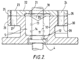
- seal carrying bush 5 is shown more clearly in Figures 2 and 3, where it will be seen that the bonnet casting 6 is provided with an appropriately shaped apertured upward protrusion 9 providing a support having a circular section aperture 10 therethrough for the correspondingly configured seal bush.
- the bush has an axial circular section aperture 11 through which is disposed the rotary control shaft 4 of the valve assembly.
- the bush seal is provided with a chamber 12 to take an appropriate O-ring (not shown) for sealing against the internal surface and the base of the aperture 10 of the bonnet casting support 9, and two internal peripheral grooves 13,14 to receive O-rings for sealing against the valve shaft 4.
- the seal bush 5 is provided on opposed diametrical sides with two lug like portions having generally axially inwardly extending V-shaped protrusions 17,18 which mate within corresponding V-shaped recesses or shoulders 19,20 disposed within the side walls of the bonnet aperture 10.
- the outer end 15 is provided with an outer extension 21 having side walls of hexagon configuration arranged to receive an appropriate sized spanner (not shown) for turning the bush 5 within the aperture in the bonnet casting aperture 10.
- a top cap 22 for safe retention of the bush 5 is located by means of nuts and bolts (not shown) via apertures 23,24 and 27,28 in external flanges 25,26 and 29,30 of the top cap 22 and bonnet casting 9 respectively.
- seal bush 5 taper somewhat from top to bottom, i.e. it is of greater diameter adjacent the outer end thereof than the inner end.
- the V-shaped protrudrances on the lugs in cooperation with the sides of the notches, assist in the removal of the bush when seal changes etc are necessary.
- the bush can be rotated, which will cause the slopes of the protrudrances of the lugs to ride up the corresponding slopes of the notches or recesses to lift the bush. Because of the taper of the bush and its receiving aperture, the bush can then readily be removed.
- a peg type of spanner may be applied to an appropriate shaped aperture in the outer end of the bush.
- the tapering on the outside of the seal bush, and the associated aperture within the bonnet casting is additionally useful in that it allows manufacture of the bush, and assists manufacture of the bonnet casting aperture, by inexpensive moulding processes where taper for the removal of cores is necessary.
- the corresponding tapered housing or aperture for the bush in the top of the valve bonnet does not require the dimensional accuracy of a housing threaded for the screwing in of bushes or of those machined for a close sliding fit.
- the design readily lends itself to the application of protective coatings such as an epoxy resin for corrosion resistant purposes.
Landscapes
- Engineering & Computer Science (AREA)
- General Engineering & Computer Science (AREA)
- Mechanical Engineering (AREA)
- Sealing Devices (AREA)
- Details Of Valves (AREA)
- Sealing With Elastic Sealing Lips (AREA)
- Sealing Of Bearings (AREA)
- Lift Valve (AREA)
- Pivots And Pivotal Connections (AREA)
- Sliding-Contact Bearings (AREA)
Claims (7)
- Hülseneinheit mit Dichtungen zum dichten Anbringen einer rotierenden Welle (4) innerhalb eines mit einer geeigneten Öffnung versehenen Tragkörpers, wobei die Hülse (5) in Form einer Buchse mit im wesentlichen kreisförmigem Querschnitt zur Aufnahme der sie durchragenden, rotierenden Welle (4) und zum Einsetzen in eine entsprechende innere, einen kreisförmigen Querschnitt aufweisende Öffnung (10) des Tragkörpers (9) ausgebildet und mit zumindest einer sich nach außen erstreckenden Nase oder Schulter an ihrem Außenumfang versehen ist, dadurch gekennzeichnet, daß die Nase oder Schulter einen sich axial zum inneren Ende der Hülse (5) erstreckenden Vorsprung (17, 18) oder eine sich axial zum äußeren Ende der Hülse (5) erstreckende Aussparung aufweist, der bzw. die mit einer entsprechenden Aussparung (19, 20) bzw. einem Vorsprung des Tragkörpers (9) in Eingriff treten kann, wobei die Hülse (5), wenn sie in diesem angeordnet ist, an einer Drehung in der Öffnung (10) des Tragkörpers (9) gehindert ist, daß der Vorsprung (17, 18) und die zugehörige Aussparung (19, 20) geneigte Seitenwände besitzen, so daß sie im wesentlichen "V"-förmig ausgebildet sind, und daß Mittel (21) zum Drehen der Hülse (5) innerhalb des mit der Öffnung versehenen Tragkörpers (9) vorgesehen sind.
- Hülseneinheit nach Anspruch 1, dadurch gekennzeichnet daß, die Mittel zum Drehen der Hülse einen mehrfach facettierten Flansch (21) aufweisen, der derart angeordnet ist, daß bei dessen Drehung die Nasen die entsprechenden Wände der Aussparung (19, 20) in den Wänden der Öffnung (10) hinaufsteigen.
- Hülseneinheit nach Anspruch 1 oder 2, dadurch gekennzeichnet, daß der Vorsprung (17, 18) an der Nase oder der Schulter und die Aussparung (19, 20) im Träger (9) vorgesehen ist.
- Hülseneinheit nach Anspruch 1, 2 oder 3, dadurch gekennzeichnet, daß zumindest zwei einander diametral gegenüberliegende Vorsprünge (17, 18) und zugehörige Aussparungen (19, 20) an der Hülse (5) und am Tragkörper (9) vorgesehen sind.
- Hülseneinheit nach einem der vorangehenden Ansprüche, dadurch gekennzeichnet, daß die Nasen direkt am Außenumfang der Hülse (5) vorstehen und derart angeordnet sind, daß die sich axial erstreckenden Vorsprünge (17, 18) sich im wesentlichen axial entlang der Hülse erstrecken, um mit entsprechenden Aussparungen (19, 20) in der Wand der Öffnung (10) des Tragkörpers (9) in Eingriff zu treten.
- Hülseneinheit nach einem der Ansprüche 1 bis 4, dadurch gekennzeichnet, daß die Nasen einstückig mit einem Flansch ausgebildet sind, welcher sich nahe einem Ende der Hülse über deren Umfang erstreckt, und derart angeordnet sind, daß sich die sich axial erstreckenden Vorsprünge (17, 18) im wesentlichen derart axial entlang der Hülse erstrecken, daß sie mit entsprechenden Aussparungen (19, 20) in der Wand der Öffnung (10) des Tragkörpers (9) in Eingriff treten.
- Ventilanordnung mit einer Dichthülseneinheit nach einem der vorangehenden Ansprüche.
Applications Claiming Priority (2)
| Application Number | Priority Date | Filing Date | Title |
|---|---|---|---|
| GB9106926 | 1991-04-03 | ||
| GB9106926A GB2254399B (en) | 1991-04-03 | 1991-04-03 | Seal bushes for rotary shafts |
Publications (2)
| Publication Number | Publication Date |
|---|---|
| EP0507544A1 EP0507544A1 (de) | 1992-10-07 |
| EP0507544B1 true EP0507544B1 (de) | 1996-08-14 |
Family
ID=10692546
Family Applications (1)
| Application Number | Title | Priority Date | Filing Date |
|---|---|---|---|
| EP92302819A Expired - Lifetime EP0507544B1 (de) | 1991-04-03 | 1992-03-31 | Abdichtungshülsen für rotierende Wellen |
Country Status (8)
| Country | Link |
|---|---|
| EP (1) | EP0507544B1 (de) |
| AT (1) | ATE141392T1 (de) |
| DE (1) | DE69212682T2 (de) |
| DK (1) | DK0507544T3 (de) |
| ES (1) | ES2090502T3 (de) |
| GB (1) | GB2254399B (de) |
| GR (1) | GR3021409T3 (de) |
| IE (1) | IE66329B1 (de) |
Families Citing this family (4)
| Publication number | Priority date | Publication date | Assignee | Title |
|---|---|---|---|---|
| GB0308957D0 (en) | 2003-04-17 | 2003-05-28 | Lillishall Plastics And Engine | Tolerance ring assembly |
| US8944690B2 (en) | 2009-08-28 | 2015-02-03 | Saint-Gobain Performance Plastics Pampus Gmbh | Corrosion resistant bushing |
| TWI487850B (zh) | 2009-09-25 | 2015-06-11 | Saint Gobain Performance Plast | 用於滑移介面滑動力的公差環控制之系統、方法和裝置 |
| EP3724967B1 (de) | 2017-12-15 | 2025-10-29 | Saint-Gobain Performance Plastics Rencol Limited | Ringförmiges element, verfahren und anordnung zur bauteilverschiebungssteuerung |
Family Cites Families (4)
| Publication number | Priority date | Publication date | Assignee | Title |
|---|---|---|---|---|
| US2511109A (en) * | 1947-12-15 | 1950-06-13 | Chester G Haskell | Stuffing box |
| FR2143464B1 (de) * | 1971-06-25 | 1973-07-13 | Crane Ltd | |
| FR2570789B1 (fr) * | 1984-09-27 | 1986-12-05 | Amri | Robinet a papillon a caractere universel et procede de fabrication dudit robinet |
| DE3923494C2 (de) * | 1989-07-15 | 1994-06-16 | Freudenberg Carl Fa | Dichtung |
-
1991
- 1991-04-03 GB GB9106926A patent/GB2254399B/en not_active Expired - Lifetime
-
1992
- 1992-03-31 DE DE69212682T patent/DE69212682T2/de not_active Expired - Fee Related
- 1992-03-31 ES ES92302819T patent/ES2090502T3/es not_active Expired - Lifetime
- 1992-03-31 AT AT92302819T patent/ATE141392T1/de not_active IP Right Cessation
- 1992-03-31 DK DK92302819.5T patent/DK0507544T3/da active
- 1992-03-31 EP EP92302819A patent/EP0507544B1/de not_active Expired - Lifetime
- 1992-04-02 IE IE921051A patent/IE66329B1/en not_active IP Right Cessation
-
1996
- 1996-10-23 GR GR960402780T patent/GR3021409T3/el unknown
Also Published As
| Publication number | Publication date |
|---|---|
| DE69212682D1 (de) | 1996-09-19 |
| ES2090502T3 (es) | 1996-10-16 |
| DE69212682T2 (de) | 1997-03-06 |
| GB2254399A (en) | 1992-10-07 |
| GB9106926D0 (en) | 1991-05-22 |
| EP0507544A1 (de) | 1992-10-07 |
| DK0507544T3 (da) | 1996-12-30 |
| GR3021409T3 (en) | 1997-01-31 |
| ATE141392T1 (de) | 1996-08-15 |
| IE921051A1 (en) | 1992-10-07 |
| GB2254399B (en) | 1995-02-01 |
| IE66329B1 (en) | 1995-12-27 |
Similar Documents
| Publication | Publication Date | Title |
|---|---|---|
| US5954088A (en) | Ball valve adapted to couple with an output drive shaft of a valve control device | |
| CA2446598C (en) | Pressure relief valve with field-replaceable high corrosion-resistant components | |
| CA1228781A (en) | Tamperproof fire hydrants | |
| US4465595A (en) | Apparatus for assembly and dissassembly of a filter construction | |
| US3993284A (en) | Connection of actuator cylinder housing to valve bonnet | |
| US4666057A (en) | Cap for a reservoir | |
| US4083377A (en) | Fire hydrant with improved weather cap and bonnet arrangement | |
| CA2348485A1 (en) | Shaft and post assemblies for molten metal pumping apparatus | |
| EP0795097B1 (de) | Ventilanordnung | |
| US4616804A (en) | Gate valve | |
| EP0507544B1 (de) | Abdichtungshülsen für rotierende Wellen | |
| US5707041A (en) | Fluid control valve with fastener for ceramic valve plug | |
| US4193579A (en) | Detachable handle for control devices | |
| US5590680A (en) | External valve operating means | |
| US4884916A (en) | System for mounting a power transmission member to a shaft | |
| US5577708A (en) | Ball valve | |
| EP0100629B1 (de) | Kükenhahn | |
| GB2227811A (en) | A shroud for a fluid-flow valve | |
| EP0109806B1 (de) | Klappe oder Kugelhahn | |
| CA2495679A1 (en) | Retainer lock nut for the stem packing of a fluid pressure control device | |
| EP0298896A2 (de) | Befestigung für Ventilsitze | |
| JP3154265B2 (ja) | バルブの軸封装置 | |
| US3344683A (en) | Actuating means adapter for quarterturn valves | |
| US4986300A (en) | Bonnet nut with improved safety characteristics | |
| GB2181820A (en) | Butterfly valves |
Legal Events
| Date | Code | Title | Description |
|---|---|---|---|
| PUAI | Public reference made under article 153(3) epc to a published international application that has entered the european phase |
Free format text: ORIGINAL CODE: 0009012 |
|
| AK | Designated contracting states |
Kind code of ref document: A1 Designated state(s): AT BE CH DE DK ES FR GR IT LI LU MC NL PT SE |
|
| 17P | Request for examination filed |
Effective date: 19930330 |
|
| 17Q | First examination report despatched |
Effective date: 19941102 |
|
| GRAH | Despatch of communication of intention to grant a patent |
Free format text: ORIGINAL CODE: EPIDOS IGRA |
|
| GRAH | Despatch of communication of intention to grant a patent |
Free format text: ORIGINAL CODE: EPIDOS IGRA |
|
| GRAA | (expected) grant |
Free format text: ORIGINAL CODE: 0009210 |
|
| AK | Designated contracting states |
Kind code of ref document: B1 Designated state(s): AT BE CH DE DK ES FR GR IT LI LU MC NL PT SE |
|
| REF | Corresponds to: |
Ref document number: 141392 Country of ref document: AT Date of ref document: 19960815 Kind code of ref document: T |
|
| REF | Corresponds to: |
Ref document number: 69212682 Country of ref document: DE Date of ref document: 19960919 |
|
| REG | Reference to a national code |
Ref country code: ES Ref legal event code: FG2A Ref document number: 2090502 Country of ref document: ES Kind code of ref document: T3 |
|
| ITF | It: translation for a ep patent filed | ||
| ET | Fr: translation filed | ||
| REG | Reference to a national code |
Ref country code: ES Ref legal event code: FG2A Ref document number: 2090502 Country of ref document: ES Kind code of ref document: T3 |
|
| REG | Reference to a national code |
Ref country code: DK Ref legal event code: T3 |
|
| REG | Reference to a national code |
Ref country code: GR Ref legal event code: FG4A Free format text: 3021409 |
|
| REG | Reference to a national code |
Ref country code: PT Ref legal event code: SC4A Free format text: AVAILABILITY OF NATIONAL TRANSLATION Effective date: 19961106 |
|
| PLBE | No opposition filed within time limit |
Free format text: ORIGINAL CODE: 0009261 |
|
| STAA | Information on the status of an ep patent application or granted ep patent |
Free format text: STATUS: NO OPPOSITION FILED WITHIN TIME LIMIT |
|
| 26N | No opposition filed | ||
| PGFP | Annual fee paid to national office [announced via postgrant information from national office to epo] |
Ref country code: GR Payment date: 20060215 Year of fee payment: 15 |
|
| PGFP | Annual fee paid to national office [announced via postgrant information from national office to epo] |
Ref country code: MC Payment date: 20060228 Year of fee payment: 15 |
|
| PGFP | Annual fee paid to national office [announced via postgrant information from national office to epo] |
Ref country code: NL Payment date: 20060305 Year of fee payment: 15 |
|
| PGFP | Annual fee paid to national office [announced via postgrant information from national office to epo] |
Ref country code: FR Payment date: 20060308 Year of fee payment: 15 |
|
| PGFP | Annual fee paid to national office [announced via postgrant information from national office to epo] |
Ref country code: AT Payment date: 20060313 Year of fee payment: 15 |
|
| PGFP | Annual fee paid to national office [announced via postgrant information from national office to epo] |
Ref country code: DK Payment date: 20060321 Year of fee payment: 15 |
|
| PGFP | Annual fee paid to national office [announced via postgrant information from national office to epo] |
Ref country code: DE Payment date: 20060323 Year of fee payment: 15 |
|
| PGFP | Annual fee paid to national office [announced via postgrant information from national office to epo] |
Ref country code: LU Payment date: 20060328 Year of fee payment: 15 |
|
| PGFP | Annual fee paid to national office [announced via postgrant information from national office to epo] |
Ref country code: CH Payment date: 20060329 Year of fee payment: 15 |
|
| PGFP | Annual fee paid to national office [announced via postgrant information from national office to epo] |
Ref country code: IT Payment date: 20060331 Year of fee payment: 15 Ref country code: PT Payment date: 20060331 Year of fee payment: 15 |
|
| PGFP | Annual fee paid to national office [announced via postgrant information from national office to epo] |
Ref country code: ES Payment date: 20060425 Year of fee payment: 15 |
|
| PGFP | Annual fee paid to national office [announced via postgrant information from national office to epo] |
Ref country code: BE Payment date: 20060509 Year of fee payment: 15 |
|
| REG | Reference to a national code |
Ref country code: PT Ref legal event code: MM4A Free format text: LAPSE DUE TO NON-PAYMENT OF FEES Effective date: 20071001 |
|
| REG | Reference to a national code |
Ref country code: DK Ref legal event code: EBP |
|
| REG | Reference to a national code |
Ref country code: CH Ref legal event code: PL |
|
| PG25 | Lapsed in a contracting state [announced via postgrant information from national office to epo] |
Ref country code: AT Free format text: LAPSE BECAUSE OF NON-PAYMENT OF DUE FEES Effective date: 20070331 |
|
| NLV4 | Nl: lapsed or anulled due to non-payment of the annual fee |
Effective date: 20071001 |
|
| BERE | Be: lapsed |
Owner name: S.A. *PONT-A-MOUSSON Effective date: 20070331 |
|
| PG25 | Lapsed in a contracting state [announced via postgrant information from national office to epo] |
Ref country code: BE Free format text: LAPSE BECAUSE OF NON-PAYMENT OF DUE FEES Effective date: 20070331 |
|
| REG | Reference to a national code |
Ref country code: FR Ref legal event code: ST Effective date: 20071130 |
|
| PG25 | Lapsed in a contracting state [announced via postgrant information from national office to epo] |
Ref country code: NL Free format text: LAPSE BECAUSE OF NON-PAYMENT OF DUE FEES Effective date: 20071001 Ref country code: DE Free format text: LAPSE BECAUSE OF NON-PAYMENT OF DUE FEES Effective date: 20071002 Ref country code: PT Free format text: LAPSE BECAUSE OF NON-PAYMENT OF DUE FEES Effective date: 20071001 Ref country code: MC Free format text: LAPSE BECAUSE OF NON-PAYMENT OF DUE FEES Effective date: 20070331 |
|
| PGFP | Annual fee paid to national office [announced via postgrant information from national office to epo] |
Ref country code: SE Payment date: 20060306 Year of fee payment: 15 |
|
| PG25 | Lapsed in a contracting state [announced via postgrant information from national office to epo] |
Ref country code: CH Free format text: LAPSE BECAUSE OF NON-PAYMENT OF DUE FEES Effective date: 20070331 Ref country code: LI Free format text: LAPSE BECAUSE OF NON-PAYMENT OF DUE FEES Effective date: 20070331 |
|
| PG25 | Lapsed in a contracting state [announced via postgrant information from national office to epo] |
Ref country code: DK Free format text: LAPSE BECAUSE OF NON-PAYMENT OF DUE FEES Effective date: 20070402 |
|
| REG | Reference to a national code |
Ref country code: ES Ref legal event code: FD2A Effective date: 20070402 |
|
| PG25 | Lapsed in a contracting state [announced via postgrant information from national office to epo] |
Ref country code: SE Free format text: LAPSE BECAUSE OF NON-PAYMENT OF DUE FEES Effective date: 20070401 |
|
| PG25 | Lapsed in a contracting state [announced via postgrant information from national office to epo] |
Ref country code: FR Free format text: LAPSE BECAUSE OF NON-PAYMENT OF DUE FEES Effective date: 20070402 Ref country code: ES Free format text: LAPSE BECAUSE OF NON-PAYMENT OF DUE FEES Effective date: 20070402 |
|
| PG25 | Lapsed in a contracting state [announced via postgrant information from national office to epo] |
Ref country code: GR Free format text: LAPSE BECAUSE OF NON-PAYMENT OF DUE FEES Effective date: 20071003 |
|
| PG25 | Lapsed in a contracting state [announced via postgrant information from national office to epo] |
Ref country code: LU Free format text: LAPSE BECAUSE OF NON-PAYMENT OF DUE FEES Effective date: 20070331 |
|
| PG25 | Lapsed in a contracting state [announced via postgrant information from national office to epo] |
Ref country code: IT Free format text: LAPSE BECAUSE OF NON-PAYMENT OF DUE FEES Effective date: 20070331 |