EP0507347A2 - Verfahren und Mittel zur Herstellung von Sammelschienenverteilungssystemen, bestehend aus mehreren gleichartigen Profilen, welche geeignet sind, um Anschlüsse an jeden Punkt ihrer Länge Anzuschliessen - Google Patents
Verfahren und Mittel zur Herstellung von Sammelschienenverteilungssystemen, bestehend aus mehreren gleichartigen Profilen, welche geeignet sind, um Anschlüsse an jeden Punkt ihrer Länge Anzuschliessen Download PDFInfo
- Publication number
- EP0507347A2 EP0507347A2 EP92105906A EP92105906A EP0507347A2 EP 0507347 A2 EP0507347 A2 EP 0507347A2 EP 92105906 A EP92105906 A EP 92105906A EP 92105906 A EP92105906 A EP 92105906A EP 0507347 A2 EP0507347 A2 EP 0507347A2
- Authority
- EP
- European Patent Office
- Prior art keywords
- section
- conductor
- cross
- screws
- components
- Prior art date
- Legal status (The legal status is an assumption and is not a legal conclusion. Google has not performed a legal analysis and makes no representation as to the accuracy of the status listed.)
- Granted
Links
Images


Classifications
-
- H—ELECTRICITY
- H01—ELECTRIC ELEMENTS
- H01R—ELECTRICALLY-CONDUCTIVE CONNECTIONS; STRUCTURAL ASSOCIATIONS OF A PLURALITY OF MUTUALLY-INSULATED ELECTRICAL CONNECTING ELEMENTS; COUPLING DEVICES; CURRENT COLLECTORS
- H01R25/00—Coupling parts adapted for simultaneous co-operation with two or more identical counterparts, e.g. for distributing energy to two or more circuits
- H01R25/14—Rails or bus-bars constructed so that the counterparts can be connected thereto at any point along their length
Definitions
- the present invention relates to a process and means to provide bus bar distributing systems, wherein each bus bar comprises more uniform cross-section components, set to receive, anywhere, therealong, a number of terminals and the like, limited only by the principle of impenetrability of bodies.
- the bus bars of distributing and/or collecting electrical energy, providing for the connection of terminals and the like are individual and are rectangular in cross-section.
- the longer side of their rectangular cross-section is from three to six times as longer as the shorter side thereof.
- Such rectangular cross-section bars are drilled and tapped with mating threads, through their main surfaces, to receive the machine screws for terminal and connection fastening.
- the tapped holes are provided correctly, in number and position. Instead, when use and density of connections or terminals are unknown, the holes are provided according to an estimated modular rule, and more frequently, in accordance with a statistical probability.
- the uniform cross-section components substantially comprising each bar unit, are five, three of which are electric conductors and two are non-conductors.
- Two of the three conductor components, the bus bars, provide the parallel walls which can be engaged by the screws, fastening the terminals and the like; the third conductor component and the non- conductor components, act as encompassing members.
- the conductor component is in centripetal position, in touch with the single bars or parallel walls, which can be engaged by the screws, fastening the terminals and the like and the non- conductor components, having "L" like cross-section, are in centrifugal position which is complementary to that of the encompassing conductor component;
- the former component is a channel, which is provided, at the centre of its bottom, with a separating rib, providing, at its sides, a pair grooves, to receive the single conductor bars.
- the paired parallel single bars set with the longer side in vertical disposition, minimizes the overall dimensions thereof, while their surface area results increased.
- Insulation is provided by components of higher height, which are arranged in stepped fashion and extend over the single bars. They are placed at least at one side, or on both side in case of adjacent bar units, to provide here too, mainly in vertical direction, the necessary dielectric distance, with a minimum of overall dimensions.
- cross-section of the conductor encompassing component is additional to the cross-section of the single bars, to provide, coeteris paribus , a compacted ensemble.
- each bus bar unit of the cross-section between 200 and 800 mm2
- two single bars of copper between mm 5 x mm 20 and mm 5 x mm 80 contained by an aluminium channel rod length of the dimensions of mm 17,5 x mm 20 x mm 2,5, are provided.
- the single bars standing with the short side of the rectangular cross-section against the inner bottom of the channel, are fit aside the rib, in order to provide their adjacent main surfaces parallel, at a distance of mm 5.
- This distance is correct to receive any so said "Parker” screw or equivalent, having an outer diameter of mm 6,3, and a length between 20 mm and 40 mm, i.e. shorter than the corresponding dimension of single bars.
- Such screws are duly provided with lock washers and applied to terminals and the like, whereby they cut their own thread into the single bars of copper, along an height L concerned between mm 18 and mm 38.
- the so fastened terminal provides a contact in at least four spots, with a conductivity increase of about 80%.
- a binding frame is provided substantially comprising two "Y" like uniform cross-sectioned rod components, fit longitudinally, which are a materialization too, of the principle of the present invention, being adapted to receive self-tapping screws in any cross-section thereof.
- This arrangement is very important also from the electric point of view, since as material, one with a good conductivity, such as aluminium, is chosen, to be adapted to connect, by self-tapping screws, driven into the more grooves, of which they are provided, the grounded terminals.
- the rods with uniform cross-section providing the binding structure, can be connected, crosswise, at the bottom by screws, i.e., self-tapping screws, engaging the ends of a distancing rod, it too comprised by uniform cross-section rods.
- screws i.e., self-tapping screws
- the structural components rods are connected through staples, thickness, self-tapping screws and bridges, all of them, except the screws, comprised by uniform cross-section rods.
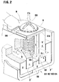
- Each bus bar unit comprises more component rods 1, 1', 2, 3, 3, all of them having uniform cross-section, set to receive, anywhere, therealong, a number of adjacent terminals 9 and the like, limited only by the principle of impenetrability of bodies.
- the uniform cross-section components are five 1, 1', 2, 3, 3. Three of them: 1, 1', 2, are conductors and two, 3 non conductors.
- the two conductor components 1, 1' provide the parallel walls 10, 10', which can be engaged by the screws 5, fastening the terminals and the like and the third conductor component 2, and insulator components 3, provide encompassing functions: the conductor member 2 is in centripetal position, in touch, even through the rib 2', with the single bars 1,1' or parallel walls 10, 10' which can be engaged by the screws 5, fastening the terminals 9 and the like; the insulator components 3 are in centrifugal position which is complementary to that of enveloping conductor component 2; the former 2 having "U” or "C” or channel like cross-section, the latter 3 having "L” like cross-section.
- the insulation space between bar units 01, 02, 03, 04, is provided by components 3 of higher height; they are coupled in stepped conditions and project from the upper side of single bars 1, 1'; they are fit paired to adjacent bar units 01, 02, 03, 04, to provide here too, mainly in vertical direction, the necessary dielectric distance with minimum overall dimensions.
- the cross-section of the enveloping conductor component 2 is additional to the cross-section of the single bars 1, 1' to provide, coeteris paribus a compacted unit.
- each bus bar unit 01, 02, 03, 04, of the cross-section of 200 mm2 were used two copper rectangular single bars 1, 1', of mm 5 x mm 20, contained by an aluminium channel rod 2, of the dimensions of mm 17,5 x mm 20 x mm 2,5, whose inner bottom 2'', 2''' is provided with a central rib 2', which is mm 5 width and mm 3 height.
- the single bars 1, 1' standing with the short side of the rectangular cross-section against the inner bottom of the channel rod 2, are fit, respectively into the grooves 2'', 2''', aside the rib 2', in order to provide their adjacent main surfaces 10, 10', parallel at a distance corresponding to that of rib 2' i.e., of mm 5.
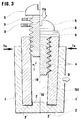
- This distance is correct to receive any of so said "Parker” screws 5 or equivalent, having an outer diameter of mm 6,3, and a length of 20 mm, i.e. shorter than the corresponding dimension of single bars 1, 1'.
- Such screws 5, are duly provided with lock washers 6 and applied to terminals 9 and the like, in order that the same screws 5 cut their own thread into the single bars 1,1' of copper, along an height L concerned of mm 18.
- the so fastened terminal 9, provides a contact in at least four spots 09, with a conductivity increase of about 80%.
- each bus bar unit 01, 02, 03, 04 having a cross-section of 500 mm2 were used two copper rectangular single bars 1, 1', of mm 5 x 50, contained by an aluminium channel rod 2, of the dimensions of mm 17,5 x mm 20 x mm 2,5,whose inner bottom is provided with a central rib 2', which is mm 5 width and mm 3 height.
- the single bars 1, 1' standing with the short side of the rectangular cross-section respectively on the bottom 2'', 2''' of the grooves siding the rib 2' of channel rod 2, in order to provide their adjacent main surfaces 10, 10' parallel at a distance corresponding to that of rib 2' i.e., of mm 5.
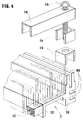
- the ensemble 3, 01, 3,3, 02, 3,3, 03, 3,3, 04, 3 is bound with an annular frame 7 comprised by a pair of uniform cross-section rod lengths 70,70', having, in general, a "Y" like cross-section, connected crosswise, at the bottom by screws, i.e., self-tapping screws 71, 71', engaging the ends of a distancing rod 72, it too comprised by uniform cross-section rods.
- the structural components rod lengths 70, 70' are connected through staples 73, thickness 74, self-tapping screws 75 and bridges 76, all of them, except the screws 75, being comprised by uniform cross-section rods.
- rod components 70, 70', 72 i.e. for all connections 9, all over the whole system, they may be made anywhere, limited only by the principle of impenetrability of bodies.
- the fastening screws 5 and the grooves 00 there is the same arrangement than between the fastening screws 5 and channel 101 provided with walls 10, 10' for terminal fastening.
- grooves 00 are adapted for grounded conductors terminals 9 (figures 4 and 5) which can be fastened with screws 5.
- the same grooves 00 may be used for structural binding as in the case of screws 71, 71', 75.
Landscapes
- Analysing Materials By The Use Of Radiation (AREA)
- Crystals, And After-Treatments Of Crystals (AREA)
- Paper (AREA)
- Multi-Conductor Connections (AREA)
- Installation Of Bus-Bars (AREA)
- Warehouses Or Storage Devices (AREA)
- Connection Or Junction Boxes (AREA)
- Coupling Device And Connection With Printed Circuit (AREA)
Applications Claiming Priority (2)
| Application Number | Priority Date | Filing Date | Title |
|---|---|---|---|
| ITVA910009A IT1249807B (it) | 1991-04-05 | 1991-04-05 | Procedimento e mezzi di allestimento di sistemi di distribuzione a sbarre,cosiddette omnibus, ove ciascuna sbarra comprende piu' componenti a sezione costante,predisposti a ricevere, in corrispondenza di indefiniti segmenti della loro lunghezza, ovunque localizzabili sugli stessi, un numero di capicorda adiacenti, |
| ITVA910009 | 1991-04-05 |
Publications (3)
| Publication Number | Publication Date |
|---|---|
| EP0507347A2 true EP0507347A2 (de) | 1992-10-07 |
| EP0507347A3 EP0507347A3 (en) | 1993-08-04 |
| EP0507347B1 EP0507347B1 (de) | 1998-06-24 |
Family
ID=11423119
Family Applications (1)
| Application Number | Title | Priority Date | Filing Date |
|---|---|---|---|
| EP92105906A Expired - Lifetime EP0507347B1 (de) | 1991-04-05 | 1992-04-06 | Sammelschienenverteilungssystem |
Country Status (5)
| Country | Link |
|---|---|
| EP (1) | EP0507347B1 (de) |
| AT (1) | ATE167760T1 (de) |
| DE (1) | DE69225991T2 (de) |
| DK (1) | DK0507347T3 (de) |
| IT (1) | IT1249807B (de) |
Cited By (1)
| Publication number | Priority date | Publication date | Assignee | Title |
|---|---|---|---|---|
| US9816544B2 (en) * | 2014-06-25 | 2017-11-14 | Ford Global Technologies, Llc | Method of forming a grounding point on an aluminum member |
Family Cites Families (2)
| Publication number | Priority date | Publication date | Assignee | Title |
|---|---|---|---|---|
| DE3151996A1 (de) * | 1981-12-31 | 1983-07-07 | Elektra GmbH & Co KG, 4904 Enger | Niedervolt-stromschiene |
| DE3607760C2 (de) * | 1985-03-18 | 1994-04-21 | Geco Sicherungstechnik | Grundplatte aus Stahlblech für Kabelverteilerkästen |
-
1991
- 1991-04-05 IT ITVA910009A patent/IT1249807B/it active IP Right Grant
-
1992
- 1992-04-06 EP EP92105906A patent/EP0507347B1/de not_active Expired - Lifetime
- 1992-04-06 DE DE69225991T patent/DE69225991T2/de not_active Expired - Fee Related
- 1992-04-06 AT AT92105906T patent/ATE167760T1/de not_active IP Right Cessation
- 1992-04-06 DK DK92105906T patent/DK0507347T3/da active
Cited By (1)
| Publication number | Priority date | Publication date | Assignee | Title |
|---|---|---|---|---|
| US9816544B2 (en) * | 2014-06-25 | 2017-11-14 | Ford Global Technologies, Llc | Method of forming a grounding point on an aluminum member |
Also Published As
| Publication number | Publication date |
|---|---|
| IT1249807B (it) | 1995-03-28 |
| EP0507347B1 (de) | 1998-06-24 |
| DE69225991T2 (de) | 1999-04-01 |
| DK0507347T3 (da) | 1999-06-23 |
| EP0507347A3 (en) | 1993-08-04 |
| ATE167760T1 (de) | 1998-07-15 |
| DE69225991D1 (de) | 1998-07-30 |
| ITVA910009A1 (it) | 1992-10-05 |
| ITVA910009A0 (it) | 1991-04-05 |
Similar Documents
| Publication | Publication Date | Title |
|---|---|---|
| US4009920A (en) | Power tap-off unit for use at a single-bolt joint in a busway system | |
| DE69511156T2 (de) | Sammelschienenanordnung, insbesondere für eine Energieverteilungsschrank | |
| US4030794A (en) | Bus bar and switchboard assemblage | |
| US3725851A (en) | Connector for high amperage applications | |
| EP2170123B1 (de) | Etagenträgersystem | |
| WO1989012341A1 (fr) | Barre omnibus pour canalisations electriques prefabriquees, installations electriques de distribution et similaire | |
| PL175306B1 (pl) | Klinowe złącze uziemiające | |
| US6290531B1 (en) | Electric cable and connector for use with a cramping terminal | |
| EP1139496A2 (de) | Verbinder für ein Freileitungskabel | |
| DE4013223C2 (de) | Netzeinspeiseklemme | |
| EP0807328B1 (de) | Stromsammelschiene | |
| EP0475417B2 (de) | Anordnung von Führungselementen für elektrische Leitungen im Fassadenbereich von Gebäuden | |
| US3509514A (en) | Connection means for electrical bus bars | |
| US3732530A (en) | Connector for high amperage applications | |
| US5035636A (en) | Disc stack connector | |
| EP0507347A2 (de) | Verfahren und Mittel zur Herstellung von Sammelschienenverteilungssystemen, bestehend aus mehreren gleichartigen Profilen, welche geeignet sind, um Anschlüsse an jeden Punkt ihrer Länge Anzuschliessen | |
| CN1225755C (zh) | 用于额定电流不同的电气仪器和设备的连接母线 | |
| CN1221231A (zh) | 具有噪音滤除功能的汇流条结构 | |
| KR102175332B1 (ko) | 부스바 체결장치 | |
| US6201722B1 (en) | Inter-bay bipolar DC bus link | |
| US4311353A (en) | Switchgear bus and connection structure | |
| DE69411294T2 (de) | Anschlussblock für elektrisches Geräte und Leistungsumformer mit einem derartigen Anschlu block | |
| CN212649037U (zh) | 一种用于配电控制设备的母线槽连接器 | |
| EP3499668B1 (de) | Modulares halteelement zur befestigung einer elektrischen sammelschiene und halteeinrichtung enthaltend eine vielzahl solcher halteelemente | |
| EP1215789A1 (de) | Sammelschienensystem für elektrische Versorgung |
Legal Events
| Date | Code | Title | Description |
|---|---|---|---|
| PUAI | Public reference made under article 153(3) epc to a published international application that has entered the european phase |
Free format text: ORIGINAL CODE: 0009012 |
|
| AK | Designated contracting states |
Kind code of ref document: A2 Designated state(s): AT BE CH DE DK ES FR GB GR IT LI LU NL SE |
|
| PUAL | Search report despatched |
Free format text: ORIGINAL CODE: 0009013 |
|
| AK | Designated contracting states |
Kind code of ref document: A3 Designated state(s): AT BE CH DE DK ES FR GB GR IT LI LU NL SE |
|
| 17P | Request for examination filed |
Effective date: 19940117 |
|
| 17Q | First examination report despatched |
Effective date: 19950301 |
|
| GRAG | Despatch of communication of intention to grant |
Free format text: ORIGINAL CODE: EPIDOS AGRA |
|
| GRAG | Despatch of communication of intention to grant |
Free format text: ORIGINAL CODE: EPIDOS AGRA |
|
| GRAH | Despatch of communication of intention to grant a patent |
Free format text: ORIGINAL CODE: EPIDOS IGRA |
|
| GRAH | Despatch of communication of intention to grant a patent |
Free format text: ORIGINAL CODE: EPIDOS IGRA |
|
| GRAA | (expected) grant |
Free format text: ORIGINAL CODE: 0009210 |
|
| AK | Designated contracting states |
Kind code of ref document: B1 Designated state(s): AT BE CH DE DK ES FR GB GR IT LI LU NL SE |
|
| PG25 | Lapsed in a contracting state [announced via postgrant information from national office to epo] |
Ref country code: NL Free format text: LAPSE BECAUSE OF FAILURE TO SUBMIT A TRANSLATION OF THE DESCRIPTION OR TO PAY THE FEE WITHIN THE PRESCRIBED TIME-LIMIT Effective date: 19980624 Ref country code: GR Free format text: LAPSE BECAUSE OF NON-PAYMENT OF DUE FEES Effective date: 19980624 Ref country code: ES Free format text: THE PATENT HAS BEEN ANNULLED BY A DECISION OF A NATIONAL AUTHORITY Effective date: 19980624 Ref country code: BE Free format text: LAPSE BECAUSE OF FAILURE TO SUBMIT A TRANSLATION OF THE DESCRIPTION OR TO PAY THE FEE WITHIN THE PRESCRIBED TIME-LIMIT Effective date: 19980624 Ref country code: AT Free format text: LAPSE BECAUSE OF FAILURE TO SUBMIT A TRANSLATION OF THE DESCRIPTION OR TO PAY THE FEE WITHIN THE PRESCRIBED TIME-LIMIT Effective date: 19980624 |
|
| REF | Corresponds to: |
Ref document number: 167760 Country of ref document: AT Date of ref document: 19980715 Kind code of ref document: T |
|
| REG | Reference to a national code |
Ref country code: CH Ref legal event code: EP |
|
| REF | Corresponds to: |
Ref document number: 69225991 Country of ref document: DE Date of ref document: 19980730 |
|
| REG | Reference to a national code |
Ref country code: CH Ref legal event code: NV Representative=s name: SASSI ROMANO C/O PONTI GUIDO |
|
| ET | Fr: translation filed | ||
| NLV1 | Nl: lapsed or annulled due to failure to fulfill the requirements of art. 29p and 29m of the patents act | ||
| PG25 | Lapsed in a contracting state [announced via postgrant information from national office to epo] |
Ref country code: LU Free format text: LAPSE BECAUSE OF NON-PAYMENT OF DUE FEES Effective date: 19990406 |
|
| PLBE | No opposition filed within time limit |
Free format text: ORIGINAL CODE: 0009261 |
|
| STAA | Information on the status of an ep patent application or granted ep patent |
Free format text: STATUS: NO OPPOSITION FILED WITHIN TIME LIMIT |
|
| 26N | No opposition filed | ||
| REG | Reference to a national code |
Ref country code: DK Ref legal event code: T3 |
|
| PGFP | Annual fee paid to national office [announced via postgrant information from national office to epo] |
Ref country code: SE Payment date: 20010323 Year of fee payment: 10 |
|
| PGFP | Annual fee paid to national office [announced via postgrant information from national office to epo] |
Ref country code: GB Payment date: 20010406 Year of fee payment: 10 |
|
| PGFP | Annual fee paid to national office [announced via postgrant information from national office to epo] |
Ref country code: DK Payment date: 20010410 Year of fee payment: 10 |
|
| PGFP | Annual fee paid to national office [announced via postgrant information from national office to epo] |
Ref country code: DE Payment date: 20010412 Year of fee payment: 10 |
|
| PGFP | Annual fee paid to national office [announced via postgrant information from national office to epo] |
Ref country code: FR Payment date: 20010413 Year of fee payment: 10 |
|
| PGFP | Annual fee paid to national office [announced via postgrant information from national office to epo] |
Ref country code: CH Payment date: 20010716 Year of fee payment: 10 |
|
| REG | Reference to a national code |
Ref country code: GB Ref legal event code: IF02 |
|
| PG25 | Lapsed in a contracting state [announced via postgrant information from national office to epo] |
Ref country code: GB Free format text: LAPSE BECAUSE OF NON-PAYMENT OF DUE FEES Effective date: 20020406 |
|
| PG25 | Lapsed in a contracting state [announced via postgrant information from national office to epo] |
Ref country code: SE Free format text: LAPSE BECAUSE OF NON-PAYMENT OF DUE FEES Effective date: 20020407 |
|
| PG25 | Lapsed in a contracting state [announced via postgrant information from national office to epo] |
Ref country code: LI Free format text: LAPSE BECAUSE OF NON-PAYMENT OF DUE FEES Effective date: 20020430 Ref country code: DK Free format text: LAPSE BECAUSE OF NON-PAYMENT OF DUE FEES Effective date: 20020430 Ref country code: CH Free format text: LAPSE BECAUSE OF NON-PAYMENT OF DUE FEES Effective date: 20020430 |
|
| PG25 | Lapsed in a contracting state [announced via postgrant information from national office to epo] |
Ref country code: DE Free format text: LAPSE BECAUSE OF NON-PAYMENT OF DUE FEES Effective date: 20021101 |
|
| EUG | Se: european patent has lapsed |
Ref document number: 92105906.9 |
|
| GBPC | Gb: european patent ceased through non-payment of renewal fee |
Effective date: 20020406 |
|
| REG | Reference to a national code |
Ref country code: CH Ref legal event code: PL |
|
| REG | Reference to a national code |
Ref country code: DK Ref legal event code: EBP |
|
| PG25 | Lapsed in a contracting state [announced via postgrant information from national office to epo] |
Ref country code: FR Free format text: LAPSE BECAUSE OF NON-PAYMENT OF DUE FEES Effective date: 20021231 |
|
| REG | Reference to a national code |
Ref country code: FR Ref legal event code: ST |
|
| PG25 | Lapsed in a contracting state [announced via postgrant information from national office to epo] |
Ref country code: IT Free format text: LAPSE BECAUSE OF NON-PAYMENT OF DUE FEES Effective date: 20050406 |