EP0507335B1 - Gerät zum Messen der Haftfestigkeit von Kunststoffschichten, die auf zylindrischen Körpern mit kleinem Durchmesser aufgebracht werden - Google Patents
Gerät zum Messen der Haftfestigkeit von Kunststoffschichten, die auf zylindrischen Körpern mit kleinem Durchmesser aufgebracht werden Download PDFInfo
- Publication number
- EP0507335B1 EP0507335B1 EP19920105804 EP92105804A EP0507335B1 EP 0507335 B1 EP0507335 B1 EP 0507335B1 EP 19920105804 EP19920105804 EP 19920105804 EP 92105804 A EP92105804 A EP 92105804A EP 0507335 B1 EP0507335 B1 EP 0507335B1
- Authority
- EP
- European Patent Office
- Prior art keywords
- tool
- small
- adhesion
- blades
- measuring
- Prior art date
- Legal status (The legal status is an assumption and is not a legal conclusion. Google has not performed a legal analysis and makes no representation as to the accuracy of the status listed.)
- Expired - Lifetime
Links
Images

Classifications
-
- G—PHYSICS
- G02—OPTICS
- G02B—OPTICAL ELEMENTS, SYSTEMS OR APPARATUS
- G02B6/00—Light guides; Structural details of arrangements comprising light guides and other optical elements, e.g. couplings
- G02B6/24—Coupling light guides
- G02B6/245—Removing protective coverings of light guides before coupling
-
- G—PHYSICS
- G01—MEASURING; TESTING
- G01N—INVESTIGATING OR ANALYSING MATERIALS BY DETERMINING THEIR CHEMICAL OR PHYSICAL PROPERTIES
- G01N19/00—Investigating materials by mechanical methods
- G01N19/04—Measuring adhesive force between materials, e.g. of sealing tape, of coating
Definitions
- the present invention concerns instruments for measuring mechanical properties of materials and more particularly it relates to a tool for measuring the adhesion of plastic-material layers deposited on small-diameter cylindrical objects, such as small bars, wires, fibres and the like. Such objects are widely used. They are coated with one or more layers of plastic material, e.g. varnishes, lacquers and the like, for aesthetic, protective, or other technical reasons. It would be useful to measure the adhesion strength of said coating layers on the cylindrical object, in order to evaluate the efficiency of the protective action exerted by the layers and their resistance to stresses.
- Presently, methods for measuring the adhesion of coating layers deposited on plane or nearly-plane surfaces are known and are objects of various standards.
- telecommunications optical fibres are long wires of circular section with a diameter of 125 ⁇ m, made of silica glass. They are offered on the market after being coated with one or two layers of plastic material with the aim of protecting their surfaces from mechanical type injuries. Namely, injuries due to atmospheric dust, causing a lot of microcracks on the glass surface, which afterwards advance towards the inside till the fibre is broken when submitted to a mechanical stress.
- the mean value of the recorded strength in the most constant segments of the trace is generally taken as adhesion value. It is also possible to make reference to minimum values appearing on the trace, or to make reference to maxima. Apart from these differences which could be overcome with the introduction of proper standards, the method does not offer repeatable values. In fact, beside being affected by ambient humidity and temperature, it gives different results in function of tool kind and blade wear and the response fluctuations highly affect mean value measurement, even though the conditions remain the same.
- the present invention provides a tool for measuring the adhesion of plastic-material layers deposited on cylindrical objects, having means for determining the force necessary to strip the coating layers and provided with blades having an aperture with a diameter slightly greater than the diameter of the cylindrical object, characterized in that each of the blades has the shape which is obtained by cutting by an axial plane the solid comprised between two coaxial frustums intersecting each other so as to have a common small base.
- Fig.1 shows an optical fibre FO, covered with coating layers SC, which is held at one end by a pair of jaws G1 and G2, while at the other it is inserted in a tool with blades C1 and C2, closed together by a suitable strength P and joined by an element B.
- the blades cut all the coating layers SC, but not fibre FO owing to their shape, which gives rise to a hole of diameter slightly greater than 125 ⁇ m, when they are fully closed.
- the tool is then drawn with force S, at a constant predetermined speed, with a recording dynamometer.
- the force necessary to strip the coating layers, still keeping the speed constant, is recorded in function of time, and therefore in function of the tool path, thus obtaining a trace.
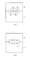
- Fig.2 shows the portion of the tool wherein the blades C1 and C2 come to contact, leaving in the axial part a circular hole BU with a diameter slightly greater than that of the fibre.
- blades C1 and C2 which are not plane. When they are fully closed, they take up the shape of the solid comprised between two coaxial frustums intersecting each other in correspondence with their small bases, which present a diameter slightly greater than the fibre diameter deprived of the coating layers.
- Each blade is obtained by section of the solid above by an axial plane, if the tool is formed by only two blades, or by means of two or three axial planes if the blade number is higher, e.g. three or four.
- Conic shape helps detach the coating layers from the cylindrical fibre, without causing more or less pronounced ripples which are the main cause of trace fluctuations and scanty measurement repeatability.
- the tool fully closes only after a certain translation, even with a null or nearly null closure strength P.
- Fig.3 shows a second version of the tool, apt to adhesion measurement of the first coating layer of optical fibres placed in a ribbon-like cable.
- the blade shape is of course still that obtained by cutting by an axial plane a plurality of solids comprised between two coaxial frustums intersecting each other in correspondence with their small bases BU1, BU2, BU3, BU4 and placed side by side with parallel axes lying on said plane.
- Fig.4 shows a third version of the tool for measuring the adhesion of the second coating layer surrounding the four fibres of a ribbon-like cable, individually coated with the first layer.
- the blade shape is equal to that of the already examined blades, with the only difference that the holes resulting in closure position have larger diameter and superpose, giving rise to a single slot FE.
Landscapes
- Physics & Mathematics (AREA)
- General Physics & Mathematics (AREA)
- General Health & Medical Sciences (AREA)
- Immunology (AREA)
- Life Sciences & Earth Sciences (AREA)
- Chemical & Material Sciences (AREA)
- Analytical Chemistry (AREA)
- Biochemistry (AREA)
- Optics & Photonics (AREA)
- Health & Medical Sciences (AREA)
- Pathology (AREA)
- Investigating Strength Of Materials By Application Of Mechanical Stress (AREA)
- Sampling And Sample Adjustment (AREA)
- Testing Of Devices, Machine Parts, Or Other Structures Thereof (AREA)
- Holding Or Fastening Of Disk On Rotational Shaft (AREA)
- Laminated Bodies (AREA)
Claims (4)
- Gerät zum Messen der Haftfestigkeit von Kunststoffschichten, die auf zylindrischen Körpern mit kleinem Durchmesser wie kleinen Stäben, Drähten oder Fasern aufgebracht sind, mit einer Einrichtung zum Bestimmen der beim Ablösen der Überzugsschichten erforderlichen Kraft und mit Schneidwerkzeugen (C1, C2), die eine Öffnung mit einem geringfügig größerem Durchmesser als dem Durchmesser des zylindrischen Körpers haben, dadurch gekennzeichnet, daß jedes der Schneidwerkzeuge die Form hat, die durch Schneiden des Raumkörpers in einer Axialebene entsteht, der zwischen zwei koaxialen Kegelstümpfen eingeschlossen ist, welche sich so durchdringen, daß sie eine gemeinsame kleine Grundfläche (BU) haben.
- Gerät nach Anspruch 1, dadurch gekennzeichnet, daß jedes der Schneidwerkzeuge (C1, C2) die durch Schneiden des Raumkörpers in zwei oder mehr Axialebenen erhaltene Form aufweist.
- Gerät zum Messen der Haftfestigkeit von Kunststoffschichten, die auf zylindrischen Körpern mit kleinem Durchmesser wie kleinen Stäben, Drähten oder Fasern aufgebracht sind, mit einer Einrichtung zum Bestimmen der beim Ablösen der Überzugsschichten erforderlichen Kraft und mit Schneidwerkzeugen (C1, C2), die eine Öffnung mit einem geringfügig größerem Durchmesser als dem Durchmesser des zylindrischen Körpers haben, dadurch gekennzeichnet, daß jedes der Schneidwerkzeuge die Form aufweist, die durch Schneiden einer Mehrzahl von Raumkörpern in einer Axialebene entsteht, die jeweils zwischen zwei koaxialen Kegelstümpfen eingeschlossen sind, welche sich so durchdringen, daß sie gemeinsame kleine Grundflächen (BU1, BU2, BU3, BU4) haben, und die Seite an Seite mit parallelen und in dieser Ebene liegenden Achsen angeordnet sind.
- Gerät nach Anspruch 3, dadurch gekennzeichnet, daß die kleinen Grundflächen einander unter Entstehung eines Schlitzes (FE) überdecken.
Applications Claiming Priority (2)
| Application Number | Priority Date | Filing Date | Title |
|---|---|---|---|
| ITUM910074U | 1991-04-04 | ||
| ITUM910074 | 1991-04-04 |
Publications (2)
| Publication Number | Publication Date |
|---|---|
| EP0507335A1 EP0507335A1 (de) | 1992-10-07 |
| EP0507335B1 true EP0507335B1 (de) | 1996-01-10 |
Family
ID=11423091
Family Applications (1)
| Application Number | Title | Priority Date | Filing Date |
|---|---|---|---|
| EP19920105804 Expired - Lifetime EP0507335B1 (de) | 1991-04-04 | 1992-04-03 | Gerät zum Messen der Haftfestigkeit von Kunststoffschichten, die auf zylindrischen Körpern mit kleinem Durchmesser aufgebracht werden |
Country Status (2)
| Country | Link |
|---|---|
| EP (1) | EP0507335B1 (de) |
| DE (2) | DE507335T1 (de) |
Family Cites Families (5)
| Publication number | Priority date | Publication date | Assignee | Title |
|---|---|---|---|---|
| US2480107A (en) * | 1945-05-21 | 1949-08-30 | Standard Telephones Cables Ltd | Cable stripping tool |
| US2929285A (en) * | 1956-11-26 | 1960-03-22 | Sperry Rand Corp | Method and machine for stripping metal braid from the end of shielded wire or cable |
| GB2104225B (en) * | 1981-08-06 | 1985-05-09 | Standard Telephones Cables Ltd | Testing plastics coatings on optical fibres |
| GB8709078D0 (en) * | 1987-04-15 | 1987-05-20 | Bicc Plc | Stripping optical fibres |
| GB2211672B (en) * | 1987-10-29 | 1991-07-03 | Josef Krampe | Apparatus for removing fibre optic cable cladding and coating |
-
1992
- 1992-04-03 EP EP19920105804 patent/EP0507335B1/de not_active Expired - Lifetime
- 1992-04-03 DE DE1992105804 patent/DE507335T1/de active Pending
- 1992-04-03 DE DE1992607461 patent/DE69207461T2/de not_active Expired - Fee Related
Also Published As
| Publication number | Publication date |
|---|---|
| DE507335T1 (de) | 1993-04-29 |
| EP0507335A1 (de) | 1992-10-07 |
| DE69207461T2 (de) | 1996-06-27 |
| DE69207461D1 (de) | 1996-02-22 |
Similar Documents
| Publication | Publication Date | Title |
|---|---|---|
| AU2014256932B2 (en) | Fiber-grating sensors having longitudinal-strain-inducing jackets and sensor systems and structures including such sensors | |
| US4346601A (en) | Testing glass fibres | |
| US3982123A (en) | Optical fiber power taps | |
| CA2073162C (en) | Fiber optic bending and positioning sensor | |
| US6148130A (en) | Cable with predetermined discrete connectorization locations | |
| US3936631A (en) | Optical fiber power tap | |
| US4875758A (en) | Plastic-coated optical transmission fiber and an estimating method thereof | |
| CA2237197C (en) | Sensor arrangement | |
| EP1254354A1 (de) | Flexible faseroptische mikrobiegeeinrichtung, sensoren, und ein verfahren zu deren verwendung | |
| US5455551A (en) | Integrated temperature sensing duct spacer unit and method of forming | |
| CA2254805A1 (en) | Optical fiber products having a stress indicating capability and process for making same | |
| EP0494930B1 (de) | Optisches faserkabel zur bestimmung von temperaturänderungen | |
| EP0507335A1 (de) | Gerät zum Messen der Haftfestigkeit von Kunststoffschichten, die auf zylindrischen Körpern mit kleinem Durchmesser aufgebracht werden | |
| CN108844655B (zh) | 一种光纤光栅温湿度传感器 | |
| CN108801497A (zh) | 一种采用光纤光栅传感器的毛发式温湿度传感探头 | |
| EP0025646B1 (de) | Verfahren und Vorrichtung zum Prüfen von Glasfasern | |
| US4300338A (en) | Method of producing coaxial cable | |
| JP2000075174A (ja) | 光ファイバケーブル | |
| US4350046A (en) | Cable strain monitoring | |
| EP0449491B1 (de) | Optische Faserprüfung durch Einführung von simulierten vielfachen Abschälungen durch Biegungen | |
| CA1068953A (en) | Optical fibre connector for variable signal attenuation | |
| CN115014606A (zh) | 基于离轴互连器的光纤光栅动态扭矩测量装置及测量方法 | |
| CA1076858A (en) | Low loss directional coupling for optical fibres | |
| TR25038A (tr) | TEMAS SAHASININ ÖLCüLMESI SURETILE OPTIK FIBERLE- RIN ELASTIK VASIFLARINI TAYIN ETMEK ICIN CIHAZ VE USUL. | |
| CN118776700B (zh) | 一种插入式光纤光栅阵列温度传感器 |
Legal Events
| Date | Code | Title | Description |
|---|---|---|---|
| PUAI | Public reference made under article 153(3) epc to a published international application that has entered the european phase |
Free format text: ORIGINAL CODE: 0009012 |
|
| AK | Designated contracting states |
Kind code of ref document: A1 Designated state(s): DE FR GB IT NL SE |
|
| EL | Fr: translation of claims filed | ||
| 17P | Request for examination filed |
Effective date: 19930205 |
|
| DET | De: translation of patent claims | ||
| TCNL | Nl: translation of patent claims filed | ||
| 17Q | First examination report despatched |
Effective date: 19930408 |
|
| GRAA | (expected) grant |
Free format text: ORIGINAL CODE: 0009210 |
|
| AK | Designated contracting states |
Kind code of ref document: B1 Designated state(s): DE FR GB IT NL SE |
|
| REF | Corresponds to: |
Ref document number: 69207461 Country of ref document: DE Date of ref document: 19960222 |
|
| ITF | It: translation for a ep patent filed | ||
| ET | Fr: translation filed | ||
| PLBE | No opposition filed within time limit |
Free format text: ORIGINAL CODE: 0009261 |
|
| STAA | Information on the status of an ep patent application or granted ep patent |
Free format text: STATUS: NO OPPOSITION FILED WITHIN TIME LIMIT |
|
| 26N | No opposition filed | ||
| REG | Reference to a national code |
Ref country code: FR Ref legal event code: TP Ref country code: FR Ref legal event code: CD |
|
| NLS | Nl: assignments of ep-patents |
Owner name: TELECOM ITALIA S.P.A. |
|
| REG | Reference to a national code |
Ref country code: GB Ref legal event code: 732E |
|
| PGFP | Annual fee paid to national office [announced via postgrant information from national office to epo] |
Ref country code: DE Payment date: 20010326 Year of fee payment: 10 |
|
| PGFP | Annual fee paid to national office [announced via postgrant information from national office to epo] |
Ref country code: GB Payment date: 20010328 Year of fee payment: 10 |
|
| PGFP | Annual fee paid to national office [announced via postgrant information from national office to epo] |
Ref country code: SE Payment date: 20010404 Year of fee payment: 10 |
|
| PGFP | Annual fee paid to national office [announced via postgrant information from national office to epo] |
Ref country code: FR Payment date: 20010409 Year of fee payment: 10 |
|
| PGFP | Annual fee paid to national office [announced via postgrant information from national office to epo] |
Ref country code: NL Payment date: 20010430 Year of fee payment: 10 |
|
| REG | Reference to a national code |
Ref country code: GB Ref legal event code: IF02 |
|
| PG25 | Lapsed in a contracting state [announced via postgrant information from national office to epo] |
Ref country code: GB Free format text: LAPSE BECAUSE OF NON-PAYMENT OF DUE FEES Effective date: 20020403 |
|
| PG25 | Lapsed in a contracting state [announced via postgrant information from national office to epo] |
Ref country code: SE Free format text: LAPSE BECAUSE OF NON-PAYMENT OF DUE FEES Effective date: 20020404 |
|
| PG25 | Lapsed in a contracting state [announced via postgrant information from national office to epo] |
Ref country code: DE Free format text: LAPSE BECAUSE OF NON-PAYMENT OF DUE FEES Effective date: 20021101 Ref country code: NL Free format text: LAPSE BECAUSE OF NON-PAYMENT OF DUE FEES Effective date: 20021101 |
|
| EUG | Se: european patent has lapsed |
Ref document number: 92105804.6 |
|
| GBPC | Gb: european patent ceased through non-payment of renewal fee |
Effective date: 20020403 |
|
| PG25 | Lapsed in a contracting state [announced via postgrant information from national office to epo] |
Ref country code: FR Free format text: LAPSE BECAUSE OF NON-PAYMENT OF DUE FEES Effective date: 20021231 |
|
| NLV4 | Nl: lapsed or anulled due to non-payment of the annual fee |
Effective date: 20021101 |
|
| REG | Reference to a national code |
Ref country code: FR Ref legal event code: ST |
|
| PGFP | Annual fee paid to national office [announced via postgrant information from national office to epo] |
Ref country code: IT Payment date: 20110426 Year of fee payment: 20 |