EP0506569A1 - Auf ein Stützteil gelagerte, elastische Hülse zur Verwendung beim Aufbringen einer Hülse - Google Patents
Auf ein Stützteil gelagerte, elastische Hülse zur Verwendung beim Aufbringen einer Hülse Download PDFInfo
- Publication number
- EP0506569A1 EP0506569A1 EP92400847A EP92400847A EP0506569A1 EP 0506569 A1 EP0506569 A1 EP 0506569A1 EP 92400847 A EP92400847 A EP 92400847A EP 92400847 A EP92400847 A EP 92400847A EP 0506569 A1 EP0506569 A1 EP 0506569A1
- Authority
- EP
- European Patent Office
- Prior art keywords
- support member
- tubular support
- elastic sleeve
- sleeve
- orifice
- Prior art date
- Legal status (The legal status is an assumption and is not a legal conclusion. Google has not performed a legal analysis and makes no representation as to the accuracy of the status listed.)
- Withdrawn
Links
- 239000000463 material Substances 0.000 claims description 11
- 230000001143 conditioned effect Effects 0.000 claims description 7
- 238000005520 cutting process Methods 0.000 description 2
- 229920002457 flexible plastic Polymers 0.000 description 2
- 238000009434 installation Methods 0.000 description 2
- 229920003023 plastic Polymers 0.000 description 2
- 239000004033 plastic Substances 0.000 description 2
- 238000007789 sealing Methods 0.000 description 2
- 239000004698 Polyethylene Substances 0.000 description 1
- 238000004026 adhesive bonding Methods 0.000 description 1
- 239000002390 adhesive tape Substances 0.000 description 1
- 230000007423 decrease Effects 0.000 description 1
- 230000000694 effects Effects 0.000 description 1
- 239000007788 liquid Substances 0.000 description 1
- 238000012423 maintenance Methods 0.000 description 1
- 238000004519 manufacturing process Methods 0.000 description 1
- 230000007935 neutral effect Effects 0.000 description 1
- 238000007747 plating Methods 0.000 description 1
- -1 polyethylene Polymers 0.000 description 1
- 229920000573 polyethylene Polymers 0.000 description 1
- 230000002035 prolonged effect Effects 0.000 description 1
- 238000003860 storage Methods 0.000 description 1
Images
Classifications
-
- B—PERFORMING OPERATIONS; TRANSPORTING
- B29—WORKING OF PLASTICS; WORKING OF SUBSTANCES IN A PLASTIC STATE IN GENERAL
- B29C—SHAPING OR JOINING OF PLASTICS; SHAPING OF MATERIAL IN A PLASTIC STATE, NOT OTHERWISE PROVIDED FOR; AFTER-TREATMENT OF THE SHAPED PRODUCTS, e.g. REPAIRING
- B29C61/00—Shaping by liberation of internal stresses; Making preforms having internal stresses; Apparatus therefor
- B29C61/06—Making preforms having internal stresses, e.g. plastic memory
- B29C61/0608—Making preforms having internal stresses, e.g. plastic memory characterised by the configuration or structure of the preforms
- B29C61/065—Preforms held in a stressed condition by means of a removable support; Supports therefor
-
- B—PERFORMING OPERATIONS; TRANSPORTING
- B29—WORKING OF PLASTICS; WORKING OF SUBSTANCES IN A PLASTIC STATE IN GENERAL
- B29C—SHAPING OR JOINING OF PLASTICS; SHAPING OF MATERIAL IN A PLASTIC STATE, NOT OTHERWISE PROVIDED FOR; AFTER-TREATMENT OF THE SHAPED PRODUCTS, e.g. REPAIRING
- B29C63/00—Lining or sheathing, i.e. applying preformed layers or sheathings of plastics; Apparatus therefor
- B29C63/18—Lining or sheathing, i.e. applying preformed layers or sheathings of plastics; Apparatus therefor using tubular layers or sheathings
- B29C63/20—Lining or sheathing, i.e. applying preformed layers or sheathings of plastics; Apparatus therefor using tubular layers or sheathings using pressure difference, e.g. vacuum
-
- H—ELECTRICITY
- H02—GENERATION; CONVERSION OR DISTRIBUTION OF ELECTRIC POWER
- H02G—INSTALLATION OF ELECTRIC CABLES OR LINES, OR OF COMBINED OPTICAL AND ELECTRIC CABLES OR LINES
- H02G1/00—Methods or apparatus specially adapted for installing, maintaining, repairing or dismantling electric cables or lines
- H02G1/14—Methods or apparatus specially adapted for installing, maintaining, repairing or dismantling electric cables or lines for joining or terminating cables
-
- B—PERFORMING OPERATIONS; TRANSPORTING
- B29—WORKING OF PLASTICS; WORKING OF SUBSTANCES IN A PLASTIC STATE IN GENERAL
- B29K—INDEXING SCHEME ASSOCIATED WITH SUBCLASSES B29B, B29C OR B29D, RELATING TO MOULDING MATERIALS OR TO MATERIALS FOR MOULDS, REINFORCEMENTS, FILLERS OR PREFORMED PARTS, e.g. INSERTS
- B29K2995/00—Properties of moulding materials, reinforcements, fillers, preformed parts or moulds
- B29K2995/0037—Other properties
- B29K2995/0046—Elastic
Definitions
- the present invention relates to an elastic sleeve conditioned on a support usable for fitting the sleeve.
- the invention applies particularly, although not exclusively, to the sheathing by an elastic sleeve of a cable end or of a cable junction.
- This document emphasizes, there is however a risk of leaks at the level of the member closing the orifice or at the level of the fixing of the elastic sleeve on the support, as well as a risk of porosity of the elastic sleeve, so that the maintenance of the elastic sleeve in the expanded position cannot be assured with certainty.
- This document also proposes to maintain the elastic sleeve in the expanded position by the introduction of a neutral liquid inside the elastic sleeve contained in a sealed enclosure or to expand the elastic sleeve on the site by means of a device fitted with a hand pump. These devices involve manipulation, admittedly not very complex, but nevertheless tedious.
- An object of the invention is to provide an elastic sleeve conditioned on a support member which can be used for fitting the sleeve by very simple operations and allowing prolonged storage.
- an assembly comprising a rigid tubular support member comprising a side wall traversed by at least one orifice equipped with a closure member, an elastic sleeve having a section at lower rest to a section of the tubular support member, this elastic sleeve being disposed inside the tubular member and having ends fixed in a sealed manner to the tubular member, and a sealed enclosure surrounding the tubular support member and delimiting an internal volume subjected to a pressure below atmospheric pressure.
- the member for closing the orifice in the side wall of the tubular support comprises a non-return valve arranged to allow air movement from a space between the tubular support member and the elastic sleeve towards the outside of this space.
- the non-return valve is formed by a segment of flexible airtight material attached to one side of the orifice.
- the sealed enclosure is produced from a flexible film and rigid perforated covers are preferably arranged at the ends of the tubular support member.
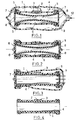
- the assembly according to the invention comprises a rigid tubular support member 1, for example a section of cylindrical tube made of rigid plastic material, the side wall of which is crossed by an orifice 2.
- the orifice 2 is covered by a segment of flexible airtight material 3, for example a strip of flexible plastic material, fixed to the external surface of the tubular support member, on one side of the orifice 2, for example by gluing.
- the flexible material segment 3 can thus beat outwards as illustrated by the double arrow in FIG. 1 and therefore forms a non-return valve.
- An elastic sleeve 4 for example a rubber sleeve, having a section at rest less than the section of the tubular support member is disposed inside the tubular support member 1 and at its ends fixed in a sealed manner with the tubular support member.
- the ends 5 of the elastic sleeve 4 have been folded over the ends of the tubular support member 1 and are held in a sealed manner either by the elasticity proper of the sleeve which tends to apply the ends 5 to the outer surface of the tubular support member 1, either by bonding the ends 5 of the sleeve to the tubular support member 1, or else by placing a retaining ring on the ends 5.
- the elastic sleeve 4 and 1 tubular support member 1 thus define an annular space 6 between the external lateral surface of the sleeve 4 and the internal lateral surface of the tubular support member 1.
- the non-return valve formed by the flexible strip segment 3 is therefore arranged to allow movement of air from the annular space 6 and to prevent movement of the air towards the interior of the annular space 6.
- rigid covers 7 having perforations 8 are arranged at the ends of the tubular support member 1 and also cover the ends of the elastic sleeve.
- the covers 7 are for example made of rigid plastic.
- the tubular support member 1 equipped with the elastic sleeve 4 and the covers 7 has simply been introduced into the sealed enclosure 9.
- the elastic sleeve 4 is then in equilibrium under the sole effect of the forces of elasticity resulting from the traction which was exerted on the ends 5 for the attach to the ends of the tubular support member 1.
- an orifice 10 of the sealed enclosure 9 is connected to a member intended to reduce the pressure inside the sealed enclosure 9, for example a pump, this operation preferably being carried out in the workshop. During this operation, the pressure gradually decreases inside the sealed enclosure 9.
- the pressure is constantly balanced between the volume opposite the internal surface of the elastic sleeve 4 and the annular space 6 comprised between the tubular support member 1 and the elastic sleeve 4.
- the elastic sleeve 4 therefore keeps the position of equilibrium shown in FIG. 1.
- the sealed enclosure 9 is progressively pressed against the external surface of the tubular support member 1 and of the covers 7.
- the opening 10 is then sealed and the conditioned elastic sleeve illustrated in FIG. 2 is obtained.
- the sealed enclosure 9 When in use, the sealed enclosure 9 is open, for example by cutting off one end as illustrated in FIG. 3, and the air then penetrates inside the sealed enclosure 9 around the member. support 1 and facing the internal surface of the elastic sleeve 4 through the perforations 8 of the covers 7. Due to the presence of the non-return valve 3, the annular volume 6 comprised between the internal face of the tubular support member 1 and the face external of the elastic sleeve 4 remains subjected to the same pressure below atmospheric pressure as in the previous step. Atmospheric pressure therefore tends to press the wall of the elastic sleeve 4 against the internal face of the tubular support member 1 and the elastic sleeve 4 assumes the expanded position illustrated in FIG. 3. The sealed enclosure 9 is then removed as well as the covers 7 and the ready-to-install sleeve illustrated in FIG. 4 is then obtained.
- the elastic sleeve 4 is arranged around the object to be sheathed and the orifice 2 is opened by tearing off the segment of flexible material 3 forming the non-return valve.
- the non-return valve 3 is therefore used only for a very short time and it can therefore be produced in a very simple manner, for example a piece of slightly adhesive tape affixed to the orifice 2 to allow it to be lifted during the setting. in depression of the enclosure and its plating on the orifice 2 during the subsequent opening of this enclosure.
Landscapes
- Engineering & Computer Science (AREA)
- Manufacturing & Machinery (AREA)
- Check Valves (AREA)
Applications Claiming Priority (2)
| Application Number | Priority Date | Filing Date | Title |
|---|---|---|---|
| FR9103864A FR2674605B1 (fr) | 1991-03-29 | 1991-03-29 | Manchon elastique conditionne sur un organe support utilisable pour une pose du manchon. |
| FR9103864 | 1991-03-29 |
Publications (1)
| Publication Number | Publication Date |
|---|---|
| EP0506569A1 true EP0506569A1 (de) | 1992-09-30 |
Family
ID=9411290
Family Applications (1)
| Application Number | Title | Priority Date | Filing Date |
|---|---|---|---|
| EP92400847A Withdrawn EP0506569A1 (de) | 1991-03-29 | 1992-03-26 | Auf ein Stützteil gelagerte, elastische Hülse zur Verwendung beim Aufbringen einer Hülse |
Country Status (2)
| Country | Link |
|---|---|
| EP (1) | EP0506569A1 (de) |
| FR (1) | FR2674605B1 (de) |
Citations (3)
| Publication number | Priority date | Publication date | Assignee | Title |
|---|---|---|---|---|
| FR2423077A1 (fr) * | 1978-04-11 | 1979-11-09 | Silec Liaisons Elec | Nouveau procede et ensemble de pose d'un manchon elastique de gainage |
| US4391661A (en) * | 1981-02-02 | 1983-07-05 | Thomas & Betts Corporation | Cable covering method using an expandable insulative sleeve |
| EP0342802A2 (de) * | 1988-05-20 | 1989-11-23 | Smiths Industries Public Limited Company | Leitung |
-
1991
- 1991-03-29 FR FR9103864A patent/FR2674605B1/fr not_active Expired - Fee Related
-
1992
- 1992-03-26 EP EP92400847A patent/EP0506569A1/de not_active Withdrawn
Patent Citations (3)
| Publication number | Priority date | Publication date | Assignee | Title |
|---|---|---|---|---|
| FR2423077A1 (fr) * | 1978-04-11 | 1979-11-09 | Silec Liaisons Elec | Nouveau procede et ensemble de pose d'un manchon elastique de gainage |
| US4391661A (en) * | 1981-02-02 | 1983-07-05 | Thomas & Betts Corporation | Cable covering method using an expandable insulative sleeve |
| EP0342802A2 (de) * | 1988-05-20 | 1989-11-23 | Smiths Industries Public Limited Company | Leitung |
Also Published As
| Publication number | Publication date |
|---|---|
| FR2674605A1 (fr) | 1992-10-02 |
| FR2674605B1 (fr) | 1993-06-04 |
Similar Documents
| Publication | Publication Date | Title |
|---|---|---|
| EP0538094B1 (de) | Metallbehälter, der entlang einer Schwächungslinie teilweise geöffnet werden kann | |
| EP0743263B1 (de) | Vorrichtung zur Aufnahme und Ausgabe von flüssigen oder pastösen Produkten | |
| WO1981001957A1 (fr) | Dispositif pour recueillir les urines d'incontinents masculins | |
| EP0549050A1 (de) | Abgabevorrichtung für wenigstens ein flüssiges Produkt, insbesondere kosmetischer oder pharmazeutischer Art | |
| FR2695628A1 (fr) | Dispositif de fermeture temporaire étanche de sac souple. | |
| EP0642839A1 (de) | Verfahren und Vorrichtung zum Spenden und Lagern eines, in einem mit Treibgas unter Druck gesetzten Behälter enthaltenen, flüssigen Produktes | |
| EP0216660A1 (de) | Vorrichtung zum Abdichten von Rohren | |
| FR2834276A1 (fr) | Dispositif de bouchage et recipient pourvu d'un tel dispositif | |
| FR2577808A1 (fr) | Dispositif d'aspiration, notamment pour ventouse aspiratrice de venin, comprenant une pompe a vide raccordable a une chambre externe | |
| EP0506569A1 (de) | Auf ein Stützteil gelagerte, elastische Hülse zur Verwendung beim Aufbringen einer Hülse | |
| FR2721188A1 (fr) | Dispositif de fermeture automatique d'un sac à poussière d'aspirateur par clapet. | |
| FR2586651A1 (fr) | Dispositif de protection d'un tube a essais | |
| CH634999A5 (fr) | Dispositif pour l'evacuation des fluides d'une plaie. | |
| EP0004802B1 (de) | Verfahren und Aggregat zum Montieren einer elastischen Ummantelungshülse | |
| FR2625179A1 (fr) | Conditionnement, tel que bouteille, bocal ou autre recipient et joint d'etancheite pour ledit conditionnement | |
| EP0494559B1 (de) | Deckel, geeignet zur Erstellung eines dichten Behälters zum Aufbewahren von Produkten wie Nahrungsmitteln | |
| EP0461007B1 (de) | Stomavorrichtung | |
| EP0669118B1 (de) | Anlegevorrichtung für einen externen Harnkatheter und Harnkatheter der eine solche Anlegevorrichtung enthält | |
| FR2629378A1 (fr) | Dispositif de formation d'une enceinte fermee a l'interieur de deux tuyauteries metalliques a raccorder par soudage a l'arc sous gaz de protection | |
| FR2528806A1 (fr) | Dispositif de support d'organe de vidange fractionnee, destine a equiper un conteneur de liquide, en particulier du type a caisse de carton et poche interieure etanche, et conteneur equipe d'un tel dispositif | |
| WO1990012554A1 (fr) | Applicateur de preservatif masculin | |
| FR2479725A1 (en) | Inflatable plastic mandrel to fit inside long pipe etc. - has protective end caps which fit snugly in each end of pipe | |
| NL9100675A (nl) | Inrichting voor het opblazen van een vingervormige ballon. | |
| FR2788732A1 (fr) | Joint pour encadrement de porte de vehicule automobile | |
| EP0751304A2 (de) | Pneumatisches Steuerungssystem, Hebevorrichtung und Steuerungssystem für einen Schrauber |
Legal Events
| Date | Code | Title | Description |
|---|---|---|---|
| PUAI | Public reference made under article 153(3) epc to a published international application that has entered the european phase |
Free format text: ORIGINAL CODE: 0009012 |
|
| 17P | Request for examination filed |
Effective date: 19920327 |
|
| AK | Designated contracting states |
Kind code of ref document: A1 Designated state(s): BE CH DE ES GB LI LU PT |
|
| 17Q | First examination report despatched |
Effective date: 19940819 |
|
| STAA | Information on the status of an ep patent application or granted ep patent |
Free format text: STATUS: THE APPLICATION IS DEEMED TO BE WITHDRAWN |
|
| 18D | Application deemed to be withdrawn |
Effective date: 19941220 |