EP0506399A1 - Single sensor apparatus and method for determining engine speed and position - Google Patents
Single sensor apparatus and method for determining engine speed and position Download PDFInfo
- Publication number
- EP0506399A1 EP0506399A1 EP92302624A EP92302624A EP0506399A1 EP 0506399 A1 EP0506399 A1 EP 0506399A1 EP 92302624 A EP92302624 A EP 92302624A EP 92302624 A EP92302624 A EP 92302624A EP 0506399 A1 EP0506399 A1 EP 0506399A1
- Authority
- EP
- European Patent Office
- Prior art keywords
- engine
- timing
- equiangular
- teeth
- predetermined
- Prior art date
- Legal status (The legal status is an assumption and is not a legal conclusion. Google has not performed a legal analysis and makes no representation as to the accuracy of the status listed.)
- Granted
Links
- 238000000034 method Methods 0.000 title claims abstract description 13
- 238000002485 combustion reaction Methods 0.000 claims abstract description 11
- 230000001360 synchronised effect Effects 0.000 claims abstract description 4
- 238000001514 detection method Methods 0.000 claims description 15
- 230000004044 response Effects 0.000 claims description 13
- 238000007493 shaping process Methods 0.000 claims description 4
- 238000006073 displacement reaction Methods 0.000 claims 1
- 239000000446 fuel Substances 0.000 description 7
- 238000002347 injection Methods 0.000 description 6
- 239000007924 injection Substances 0.000 description 6
- 230000006835 compression Effects 0.000 description 3
- 238000007906 compression Methods 0.000 description 3
- 230000005355 Hall effect Effects 0.000 description 2
- 238000004364 calculation method Methods 0.000 description 2
- 238000012986 modification Methods 0.000 description 2
- 230000004048 modification Effects 0.000 description 2
- 230000000630 rising effect Effects 0.000 description 2
- 101100428617 Homo sapiens VMP1 gene Proteins 0.000 description 1
- 101150074162 TDC1 gene Proteins 0.000 description 1
- 102100038001 Vacuole membrane protein 1 Human genes 0.000 description 1
- 230000001133 acceleration Effects 0.000 description 1
- 230000004075 alteration Effects 0.000 description 1
- 230000008878 coupling Effects 0.000 description 1
- 230000001808 coupling effect Effects 0.000 description 1
- 238000010168 coupling process Methods 0.000 description 1
- 238000005859 coupling reaction Methods 0.000 description 1
- 239000003550 marker Substances 0.000 description 1
- 230000000737 periodic effect Effects 0.000 description 1
- 230000001737 promoting effect Effects 0.000 description 1
Images
Classifications
-
- G—PHYSICS
- G01—MEASURING; TESTING
- G01D—MEASURING NOT SPECIALLY ADAPTED FOR A SPECIFIC VARIABLE; ARRANGEMENTS FOR MEASURING TWO OR MORE VARIABLES NOT COVERED IN A SINGLE OTHER SUBCLASS; TARIFF METERING APPARATUS; MEASURING OR TESTING NOT OTHERWISE PROVIDED FOR
- G01D5/00—Mechanical means for transferring the output of a sensing member; Means for converting the output of a sensing member to another variable where the form or nature of the sensing member does not constrain the means for converting; Transducers not specially adapted for a specific variable
- G01D5/12—Mechanical means for transferring the output of a sensing member; Means for converting the output of a sensing member to another variable where the form or nature of the sensing member does not constrain the means for converting; Transducers not specially adapted for a specific variable using electric or magnetic means
- G01D5/14—Mechanical means for transferring the output of a sensing member; Means for converting the output of a sensing member to another variable where the form or nature of the sensing member does not constrain the means for converting; Transducers not specially adapted for a specific variable using electric or magnetic means influencing the magnitude of a current or voltage
- G01D5/142—Mechanical means for transferring the output of a sensing member; Means for converting the output of a sensing member to another variable where the form or nature of the sensing member does not constrain the means for converting; Transducers not specially adapted for a specific variable using electric or magnetic means influencing the magnitude of a current or voltage using Hall-effect devices
- G01D5/147—Mechanical means for transferring the output of a sensing member; Means for converting the output of a sensing member to another variable where the form or nature of the sensing member does not constrain the means for converting; Transducers not specially adapted for a specific variable using electric or magnetic means influencing the magnitude of a current or voltage using Hall-effect devices influenced by the movement of a third element, the position of Hall device and the source of magnetic field being fixed in respect to each other
-
- F—MECHANICAL ENGINEERING; LIGHTING; HEATING; WEAPONS; BLASTING
- F02—COMBUSTION ENGINES; HOT-GAS OR COMBUSTION-PRODUCT ENGINE PLANTS
- F02D—CONTROLLING COMBUSTION ENGINES
- F02D41/00—Electrical control of supply of combustible mixture or its constituents
- F02D41/009—Electrical control of supply of combustible mixture or its constituents using means for generating position or synchronisation signals
-
- F—MECHANICAL ENGINEERING; LIGHTING; HEATING; WEAPONS; BLASTING
- F02—COMBUSTION ENGINES; HOT-GAS OR COMBUSTION-PRODUCT ENGINE PLANTS
- F02D—CONTROLLING COMBUSTION ENGINES
- F02D41/00—Electrical control of supply of combustible mixture or its constituents
- F02D41/0097—Electrical control of supply of combustible mixture or its constituents using means for generating speed signals
-
- F—MECHANICAL ENGINEERING; LIGHTING; HEATING; WEAPONS; BLASTING
- F02—COMBUSTION ENGINES; HOT-GAS OR COMBUSTION-PRODUCT ENGINE PLANTS
- F02P—IGNITION, OTHER THAN COMPRESSION IGNITION, FOR INTERNAL-COMBUSTION ENGINES; TESTING OF IGNITION TIMING IN COMPRESSION-IGNITION ENGINES
- F02P7/00—Arrangements of distributors, circuit-makers or -breakers, e.g. of distributor and circuit-breaker combinations or pick-up devices
- F02P7/06—Arrangements of distributors, circuit-makers or -breakers, e.g. of distributor and circuit-breaker combinations or pick-up devices of circuit-makers or -breakers, or pick-up devices adapted to sense particular points of the timing cycle
- F02P7/067—Electromagnetic pick-up devices, e.g. providing induced current in a coil
- F02P7/0675—Electromagnetic pick-up devices, e.g. providing induced current in a coil with variable reluctance, e.g. depending on the shape of a tooth
-
- G—PHYSICS
- G01—MEASURING; TESTING
- G01D—MEASURING NOT SPECIALLY ADAPTED FOR A SPECIFIC VARIABLE; ARRANGEMENTS FOR MEASURING TWO OR MORE VARIABLES NOT COVERED IN A SINGLE OTHER SUBCLASS; TARIFF METERING APPARATUS; MEASURING OR TESTING NOT OTHERWISE PROVIDED FOR
- G01D5/00—Mechanical means for transferring the output of a sensing member; Means for converting the output of a sensing member to another variable where the form or nature of the sensing member does not constrain the means for converting; Transducers not specially adapted for a specific variable
- G01D5/12—Mechanical means for transferring the output of a sensing member; Means for converting the output of a sensing member to another variable where the form or nature of the sensing member does not constrain the means for converting; Transducers not specially adapted for a specific variable using electric or magnetic means
- G01D5/14—Mechanical means for transferring the output of a sensing member; Means for converting the output of a sensing member to another variable where the form or nature of the sensing member does not constrain the means for converting; Transducers not specially adapted for a specific variable using electric or magnetic means influencing the magnitude of a current or voltage
- G01D5/142—Mechanical means for transferring the output of a sensing member; Means for converting the output of a sensing member to another variable where the form or nature of the sensing member does not constrain the means for converting; Transducers not specially adapted for a specific variable using electric or magnetic means influencing the magnitude of a current or voltage using Hall-effect devices
-
- G—PHYSICS
- G01—MEASURING; TESTING
- G01D—MEASURING NOT SPECIALLY ADAPTED FOR A SPECIFIC VARIABLE; ARRANGEMENTS FOR MEASURING TWO OR MORE VARIABLES NOT COVERED IN A SINGLE OTHER SUBCLASS; TARIFF METERING APPARATUS; MEASURING OR TESTING NOT OTHERWISE PROVIDED FOR
- G01D5/00—Mechanical means for transferring the output of a sensing member; Means for converting the output of a sensing member to another variable where the form or nature of the sensing member does not constrain the means for converting; Transducers not specially adapted for a specific variable
- G01D5/12—Mechanical means for transferring the output of a sensing member; Means for converting the output of a sensing member to another variable where the form or nature of the sensing member does not constrain the means for converting; Transducers not specially adapted for a specific variable using electric or magnetic means
- G01D5/14—Mechanical means for transferring the output of a sensing member; Means for converting the output of a sensing member to another variable where the form or nature of the sensing member does not constrain the means for converting; Transducers not specially adapted for a specific variable using electric or magnetic means influencing the magnitude of a current or voltage
- G01D5/20—Mechanical means for transferring the output of a sensing member; Means for converting the output of a sensing member to another variable where the form or nature of the sensing member does not constrain the means for converting; Transducers not specially adapted for a specific variable using electric or magnetic means influencing the magnitude of a current or voltage by varying inductance, e.g. by a movable armature
- G01D5/2006—Mechanical means for transferring the output of a sensing member; Means for converting the output of a sensing member to another variable where the form or nature of the sensing member does not constrain the means for converting; Transducers not specially adapted for a specific variable using electric or magnetic means influencing the magnitude of a current or voltage by varying inductance, e.g. by a movable armature by influencing the self-induction of one or more coils
- G01D5/2013—Mechanical means for transferring the output of a sensing member; Means for converting the output of a sensing member to another variable where the form or nature of the sensing member does not constrain the means for converting; Transducers not specially adapted for a specific variable using electric or magnetic means influencing the magnitude of a current or voltage by varying inductance, e.g. by a movable armature by influencing the self-induction of one or more coils by a movable ferromagnetic element, e.g. a core
-
- G—PHYSICS
- G01—MEASURING; TESTING
- G01D—MEASURING NOT SPECIALLY ADAPTED FOR A SPECIFIC VARIABLE; ARRANGEMENTS FOR MEASURING TWO OR MORE VARIABLES NOT COVERED IN A SINGLE OTHER SUBCLASS; TARIFF METERING APPARATUS; MEASURING OR TESTING NOT OTHERWISE PROVIDED FOR
- G01D5/00—Mechanical means for transferring the output of a sensing member; Means for converting the output of a sensing member to another variable where the form or nature of the sensing member does not constrain the means for converting; Transducers not specially adapted for a specific variable
- G01D5/12—Mechanical means for transferring the output of a sensing member; Means for converting the output of a sensing member to another variable where the form or nature of the sensing member does not constrain the means for converting; Transducers not specially adapted for a specific variable using electric or magnetic means
- G01D5/244—Mechanical means for transferring the output of a sensing member; Means for converting the output of a sensing member to another variable where the form or nature of the sensing member does not constrain the means for converting; Transducers not specially adapted for a specific variable using electric or magnetic means influencing characteristics of pulses or pulse trains; generating pulses or pulse trains
- G01D5/245—Mechanical means for transferring the output of a sensing member; Means for converting the output of a sensing member to another variable where the form or nature of the sensing member does not constrain the means for converting; Transducers not specially adapted for a specific variable using electric or magnetic means influencing characteristics of pulses or pulse trains; generating pulses or pulse trains using a variable number of pulses in a train
- G01D5/2454—Encoders incorporating incremental and absolute signals
- G01D5/2455—Encoders incorporating incremental and absolute signals with incremental and absolute tracks on the same encoder
- G01D5/2457—Incremental encoders having reference marks
-
- G—PHYSICS
- G01—MEASURING; TESTING
- G01P—MEASURING LINEAR OR ANGULAR SPEED, ACCELERATION, DECELERATION, OR SHOCK; INDICATING PRESENCE, ABSENCE, OR DIRECTION, OF MOVEMENT
- G01P3/00—Measuring linear or angular speed; Measuring differences of linear or angular speeds
- G01P3/42—Devices characterised by the use of electric or magnetic means
- G01P3/44—Devices characterised by the use of electric or magnetic means for measuring angular speed
- G01P3/48—Devices characterised by the use of electric or magnetic means for measuring angular speed by measuring frequency of generated current or voltage
- G01P3/481—Devices characterised by the use of electric or magnetic means for measuring angular speed by measuring frequency of generated current or voltage of pulse signals
- G01P3/488—Devices characterised by the use of electric or magnetic means for measuring angular speed by measuring frequency of generated current or voltage of pulse signals delivered by variable reluctance detectors
-
- G—PHYSICS
- G01—MEASURING; TESTING
- G01P—MEASURING LINEAR OR ANGULAR SPEED, ACCELERATION, DECELERATION, OR SHOCK; INDICATING PRESENCE, ABSENCE, OR DIRECTION, OF MOVEMENT
- G01P3/00—Measuring linear or angular speed; Measuring differences of linear or angular speeds
- G01P3/42—Devices characterised by the use of electric or magnetic means
- G01P3/44—Devices characterised by the use of electric or magnetic means for measuring angular speed
- G01P3/48—Devices characterised by the use of electric or magnetic means for measuring angular speed by measuring frequency of generated current or voltage
- G01P3/481—Devices characterised by the use of electric or magnetic means for measuring angular speed by measuring frequency of generated current or voltage of pulse signals
- G01P3/489—Digital circuits therefor
Definitions
- This invention relates to a position sensor suitable for use in an internal combustion engine control system, and more specifically to a single sensor system capable of determining engine speed as well as engine crankshaft or camshaft position.
- 4,870,587 combines the missing tooth detection scheme with the fact that the rotational speed of the crankshaft or camshaft after top dead center of a cylinder rises substantially relative to engine speed before top dead center in a compression stroke of the cylinder but does not rise in an exhaust stroke.
- the stroke of the engine is discriminated by determining the difference in rotational speed of the crankshaft before and after top dead center of a cylinder.
- Nomura et al. discloses a toothed wheel having several missing teeth and phase shifted teeth whereas Beyer et al. discloses a toothed wheel having one tooth which is not notched or split to provide a special timing position signal.
- a position and speed sensing apparatus for use with an internal combustion engine having a camshaft, the apparatus comprises a tone wheel adapted to rotate in synchronism with the camshaft and having a plurality of equiangularly spaced teeth, the tone wheel further having an additional tooth situated between an adjacent pair of the plurality of equiangularly spaced teeth, sensor means situated in close proximity to the tone wheel, the sensor means producing a pulse signal as each of the teeth and the additional tooth of the tone wheel pass near the sensor means, circuit means responsive to the pulse signals for producing a reference timing signal indicative of the additional tooth passing near the sensor means, and wherein the additional tooth is mechanically synchronized with a predetermined reference position of the engine.
- a method for determining engine speed and position of an internal combustion engine comprises the steps of (a) providing a rotating member which rotates in synchronism with the camshaft of the engine, and the rotating member including a plurality of equiangular projections and an additional projection situated between adjacent equiangularly spaced projections, (b) detecting the equiangular projections and the additional projection as they pass a fixed reference location and producing a series of pulse signals in response to the passage of each of the projections, (c) producing a timing reference signal when the additional projection and a subsequent one of the equiangular projections passes said reference location, and (d) producing a speed signal corresponding to the speed of the engine in response to the pulse signals.
- One object of the present invention is to provide an improved engine speed and position sensing apparatus.
- Another object of the present invention is to provide improved accuracy with regard to engine position detection in order to control a fuel injected internal combustion engine.
- Another object of the present invention is to detect top dead center timing during low engine speed conditions when engine speed fluctuations are more pronounced in response to the occurrence of compression and power strokes during cold start conditions.
- a further object of the present invention is to provide a speed and position transducer which can be readily associated with a computer to generate output signals based on signals derived from the sensor, and provide critical timing information with regard to engine control systems, particularly fuel injection systems.
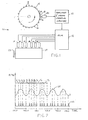
- FIG. 1 is a diagrammatic illustration of the speed and position sensing apparatus according to the present invention.
- FIG. 2 is an idealized plot of an engine RPM curve versus the sensor output signal curve and depicting the timing relationship of the two curves.
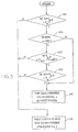
- FIG. 3 is a flowchart for the software algorithm used to determine engine position.
- Engine control module or ECM 12 is a microcomputer-based control system including RAM, ROM, EEPROM, analog I/O and digital I/O.
- Gear 14 includes a plurality of teeth 16 (24 total) which are equiangularly spaced about the perimeter of gear 14. Further, an additional tooth 18 is situated precisely between two of the equiangularly spaced teeth 16.
- a variable reluctance sensor (or Hall effect sensor) 20 supplies a signal to amplifier and signal shaping circuitry 22 corresponding to the passing of the gear teeth 16 and 18.
- Tooth 18 is located so that its passing indicates that a particular subsequent tooth approaching sensor 20 will be the tooth corresponding to top dead center of a particular reference cylinder of engine 24.
- One possible approach is to use the first tooth following the reference tooth 18 as the position reference tooth.
- every fourth tooth for example, indicates or signals the occurrence of top dead center of a predetermined cylinder in a six cylinder engine. Since gear 14 is located on the camshaft of the engine 24 and rotates in synchronism with the crankshaft 25 of engine 24, each passing of tooth 18 past sensor 20 signals that the top dead center position of a reference cylinder in the compression stroke (usually cylinder No.
- ECM 12 analyzes the signal from circuitry 22 to determine engine speed and engine position, be it crankshaft or camshaft position. It should be noted that there are 25 total teeth on gear 14, and thus the ECM may count the passage of 25 teeth by sensing 25 pulses from circuitry 22 to determine engine speed.
- ECM 12 may sense the passage of the extra tooth 18 and then measure the time required for 4 of the teeth 16 to pass sensor 20 by analyzing the signal from circuitry 22.
- the time for 4 teeth to pass will correspond with a predetermined angular rotation of the engine, and thus may be used in calculating or determining engine speed. More particularly, since there are 24 equiangularly spaced teeth 16 on gear 14, and since gear 14 rotates in synchronism with the camshaft of engine 24, the passage of 12 teeth corresponds to one revolution of the crankshaft, and the passage of 4 teeth corresponds to one-third revolution of the crankshaft of engine 24. Such calculations are well-known in the art of speed sensing and need not be further discussed herein.
- the output signal of circuitry 22 supplied to ECM 12 is shown as curve 32, and the RPM deviation of engine 24 is depicted by idealized curve 34.
- a number of time periods labeled T1-T n are shown depicting the relative time deviation between leading edges of pulses in curve 32. Labeled across the horizontal axis of the graph are the locations in time where top dead center of the various cylinders of engine 24 will occur. Particularly, top dead center of cylinder No. 1 labeled TDC1 occurs at the beginning of time T10. The beginning of time T10 is signaled by detection of the gear tooth 16 which immediately follows tooth 18 as gear 14 rotates. In view of the fact that the speed of the engine varies slightly and the speed variations are more pronounced in the lower engine speeds, the time deviations measurable between the passing of adjacent gear teeth are used to determine when tooth 18 has passed sensor 20.
- ECM 12 includes hardware and software for detecting the leading edge of each of the pulses of curve or waveform 32 and continuously maintains an array of values in memory corresponding to a fixed quantity of the most recent of time periods T1-T10 up through T n representing actual timing information.
- ECM 12 detects the leading edge of the pulse generated in response thereto and determines a time period measured between the current pulse received from circuitry 22 and the previous pulse received. It should be noted that ECM 12 need only store in memory the four most recent timed periods (T1-T n ) defined by the most recent pulses of curve 32 for purposes of RPM of RPM and position detection.
- FIG. 3 a flowchart for the software algorithm used to detect engine position is shown.
- This flowchart represents the functional algorithm of a software subroutine which executes each time a timing pulse of curve 32 is detected by ECM 12.
- program executed by ECM 12 tests to determine whether the time period T n-1 times 0.75 is greater than the time period T n . If so, program execution will continue at step 102. If the answer to the test in step 100 is no, the program determines that the next tooth is not the top dead center of cylinder No. 1 in step 110 and program execution will return to the calling routine.
- the microcomputer of ECM 12 determines whether or not the RPM determined for engine 24 is less than or equal to 300 RPM.
- step 104 program execution will continue at step 104. If the test is not true, indicating that engine RPM is greater than 300 RPM, then program execution continues with step 108 wherein the microcomputer determines that top dead center of cylinder No. 1 will correspond with the occurrence or detection of the next tooth of gear 14 at step 108. However, if the answer to the test of step 102 is yes, program execution will continue with step 104 wherein the time period for T n-3 is compared with the difference between T n-2 and 3.1 milliseconds. If T n-3 is greater than (T n-2 minus 3.1 milliseconds), then program execution will continue at step 106.
- step 104 determines whether the result of the test is an answer of "no"
- program execution continues with step 110.
- a final check at step 106 is made to compare the product of 0.875 and T n-3 with T n . If the product of 0.875 and T n-3 is greater than T n , then the next tooth detected will be top dead center of cylinder No. 1 at step 108. However, if the test at step 106 results in an answer of "no", then program execution will continue at step 110.
- the algorithm of FIG. 3 is designed specifically to detect the occurrence and sequence of time periods labeled T5-T8.
- the time periods T5 and T6 will satisfy the test in step 100.
- the tests set forth in steps 104 and 106 provide further discrimination, if necessary, to determine the position of the engine.
- T6 is quite frequently less than 75 percent of T5 during cold temperature low RPM conditions.
- the tests in steps 104 and 106 provide further discrimination and prevent false identification of the reference position tooth 18. Above approximately 300 RPM engine speed, the test in step 100 is the only test necessary to determine when top dead center of cylinder No. 1 will occur.
- steps 104 and 106 confirm the rising edge of the waveform from circuitry 22 for time period T n-3 and time period T n-2 versus time period T n which must be much shorter than time period T n-3 .
- the tests in steps 100, 104 and 106 are not satisfied in all other cases other than the one denoted by time periods T5-T8 in FIG. 2.
Landscapes
- Physics & Mathematics (AREA)
- Engineering & Computer Science (AREA)
- General Physics & Mathematics (AREA)
- Chemical & Material Sciences (AREA)
- Combustion & Propulsion (AREA)
- Mechanical Engineering (AREA)
- General Engineering & Computer Science (AREA)
- Electromagnetism (AREA)
- Combined Controls Of Internal Combustion Engines (AREA)
- Measurement Of Length, Angles, Or The Like Using Electric Or Magnetic Means (AREA)
- Ignition Installations For Internal Combustion Engines (AREA)
Abstract
Description
- This invention relates to a position sensor suitable for use in an internal combustion engine control system, and more specifically to a single sensor system capable of determining engine speed as well as engine crankshaft or camshaft position.
- It is a well-known concept to employ a toothed wheel or gear having equiangularly spaced teeth on the engine crankshaft or camshaft in conjunction with a fixed sensor to provide a pulse train output signal as the toothed wheel rotates. The pulse train signal is used to provide information about the speed of the engine. In addition, angular position may also be determined by way of analyzing the pulse train signal to provide information with regard to a specific position or tooth which has just passed the sensor. The timing information which is derived therefrom is useful in controlling ignition timing as well as timing and fueling of fuel injection systems.
- Numerous patented methods and devices are known for detecting engine position and speed. Cockerham, U.S. Patent No. 4,797,827, discloses an angular position detector which includes a toothed wheel with a missing tooth and a single sensor providing a pulse train signal corresponding to the teeth of the wheel passing nearby. A missing tooth is used to determine engine position. Other patents incorporating the missing tooth technique for determining engine position include Karle et al., U.S. Patent No. 4,982,330; Capurka, U.S. Patent No. 4,553,426; and Nakamura et al., U.S. Patent No. 4,825,373. Further, Kumagai, U.S. Patent No. 4,870,587, combines the missing tooth detection scheme with the fact that the rotational speed of the crankshaft or camshaft after top dead center of a cylinder rises substantially relative to engine speed before top dead center in a compression stroke of the cylinder but does not rise in an exhaust stroke. Thus, the stroke of the engine is discriminated by determining the difference in rotational speed of the crankshaft before and after top dead center of a cylinder.
- Another approach well-known in the art for detecting engine position and/or speed is to provide a toothed wheel wherein one of the teeth is altered slightly in shape or phase relationship with regard to the remaining gear teeth to produce an identifiable position signal thereby indicating relative position of the camshaft or crankshaft of the engine. Specifically, Lotterbach et al., U.S. Patent No. 4,700,305, discloses a device for controlling a vehicle engine computer using a segmental disk transducer for indicating a specific marker angular position of the crankshaft. The segmented disk includes uniformly spaced segments thereon wherein the number of segments corresponds to the number of cylinders. One of the segments is foreshortened, so that the passage of the leading flank thereof past a stationary pick-up transducer will occur at a time later than that of the leading edges or flanks of the remaining segments. Deutsch, U.S. Patent No. 4,941,445, discloses an electronic position sensor assembly and engine control system wherein two sensing elements in a dual sensor provide separate and independent position signals related to a multi-cylinder engine cycle position. Reference signals for determining engine position are generated in accordance with several extra-large teeth located on a rotating toothed wheel. Akasu, U.S. Patent No. 4,959,996, discloses a control signal generator for an internal combustion engine. The toothed wheel disclosed in Akasu is substantially similar to that shown in Lotterbach et al.
- Other prior art concepts for determining position and speed of an internal combustion engine are disclosed in Nomura et al., U.S. Patent No. 4,972,818, and Beyer et al., U.S. Patent No. 4,889,094. Nomura et al. discloses a toothed wheel having several missing teeth and phase shifted teeth whereas Beyer et al. discloses a toothed wheel having one tooth which is not notched or split to provide a special timing position signal.
- Systems which incorporate the missing tooth approach rely upon detection of the remaining teeth in order to establish the approximate position of the missing tooth for timing purposes. Such an approach will at times produce undesirable timing results during acceleration or deceleration of the engine when the timed projected occurrence of the missing tooth must be estimated by the engine control system.
- A more reliable and highly accurate position and speed sensor for use with an internal combustion engine is needed.
- A position and speed sensing apparatus according to the present invention for use with an internal combustion engine having a camshaft, the apparatus comprises a tone wheel adapted to rotate in synchronism with the camshaft and having a plurality of equiangularly spaced teeth, the tone wheel further having an additional tooth situated between an adjacent pair of the plurality of equiangularly spaced teeth, sensor means situated in close proximity to the tone wheel, the sensor means producing a pulse signal as each of the teeth and the additional tooth of the tone wheel pass near the sensor means, circuit means responsive to the pulse signals for producing a reference timing signal indicative of the additional tooth passing near the sensor means, and wherein the additional tooth is mechanically synchronized with a predetermined reference position of the engine.
- A method for determining engine speed and position of an internal combustion engine according to another aspect of the present invention comprises the steps of (a) providing a rotating member which rotates in synchronism with the camshaft of the engine, and the rotating member including a plurality of equiangular projections and an additional projection situated between adjacent equiangularly spaced projections, (b) detecting the equiangular projections and the additional projection as they pass a fixed reference location and producing a series of pulse signals in response to the passage of each of the projections, (c) producing a timing reference signal when the additional projection and a subsequent one of the equiangular projections passes said reference location, and (d) producing a speed signal corresponding to the speed of the engine in response to the pulse signals.
- One object of the present invention is to provide an improved engine speed and position sensing apparatus.
- Another object of the present invention is to provide improved accuracy with regard to engine position detection in order to control a fuel injected internal combustion engine.
- Another object of the present invention is to detect top dead center timing during low engine speed conditions when engine speed fluctuations are more pronounced in response to the occurrence of compression and power strokes during cold start conditions.
- A further object of the present invention is to provide a speed and position transducer which can be readily associated with a computer to generate output signals based on signals derived from the sensor, and provide critical timing information with regard to engine control systems, particularly fuel injection systems.
- FIG. 1 is a diagrammatic illustration of the speed and position sensing apparatus according to the present invention.
- FIG. 2 is an idealized plot of an engine RPM curve versus the sensor output signal curve and depicting the timing relationship of the two curves.
- FIG. 3 is a flowchart for the software algorithm used to determine engine position.
- For the purposes of promoting an understanding of the principles of the invention, reference will now be made to the embodiment illustrated in the drawings and specific language will be used to describe the same. It will nevertheless be understood that no limitation of the scope of the invention is thereby intended, such alterations and further modifications in the illustrated device, and such further applications of the principles of the invention as illustrated therein being contemplated as would normally occur to one skilled in the art to which the invention relates.
- Referring now to FIG. 1, a diagrammatic illustration of the engine speed and position sensing apparatus 10 according to the present invention is shown. Engine control module or ECM 12 is a microcomputer-based control system including RAM, ROM, EEPROM, analog I/O and digital I/O. Gear 14 includes a plurality of teeth 16 (24 total) which are equiangularly spaced about the perimeter of gear 14. Further, an
additional tooth 18 is situated precisely between two of the equiangularly spacedteeth 16. As gear 14 rotates in the direction of the arrow, a variable reluctance sensor (or Hall effect sensor) 20 supplies a signal to amplifier andsignal shaping circuitry 22 corresponding to the passing of thegear teeth Tooth 18 is located so that its passing indicates that a particular subsequenttooth approaching sensor 20 will be the tooth corresponding to top dead center of a particular reference cylinder ofengine 24. One possible approach is to use the first tooth following thereference tooth 18 as the position reference tooth. In addition, if the number of teeth 16 (here twenty-four) is a fixed multiple of the number of cylinders ofengine 24, then every fourth tooth, for example, indicates or signals the occurrence of top dead center of a predetermined cylinder in a six cylinder engine. Since gear 14 is located on the camshaft of theengine 24 and rotates in synchronism with thecrankshaft 25 ofengine 24, each passing oftooth 18past sensor 20 signals that the top dead center position of a reference cylinder in the compression stroke (usually cylinder No. 1) is about to occur. This reference information is critical in a fuel injected system since fuel injectors 25-30 require precise timed signals supplied thereto (from ECM 12) in order to appropriately control fuel injection quantities as well as timing of fuel injection with respect to the operation of a diesel engine. - Operationally speaking, as the teeth of gear 14 pass in close proximity to
sensor 20, increased magnetic coupling occurs between thegear teeth sensor 20. The periodic signal produced bysensor 20 corresponding togear teeth sensor 20 is supplied to an input of amplifier andsignal shaping circuitry 22.Circuitry 22 amplifies the signal received fromsensor 20 and transforms the signal into a squared-up pulse train signal which is supplied to an input ofECM 12.ECM 12 analyzes the signal fromcircuitry 22 to determine engine speed and engine position, be it crankshaft or camshaft position. It should be noted that there are 25 total teeth on gear 14, and thus the ECM may count the passage of 25 teeth by sensing 25 pulses fromcircuitry 22 to determine engine speed. Alternatively,ECM 12 may sense the passage of theextra tooth 18 and then measure the time required for 4 of theteeth 16 to passsensor 20 by analyzing the signal fromcircuitry 22. The time for 4 teeth to pass will correspond with a predetermined angular rotation of the engine, and thus may be used in calculating or determining engine speed. More particularly, since there are 24 equiangularly spacedteeth 16 on gear 14, and since gear 14 rotates in synchronism with the camshaft ofengine 24, the passage of 12 teeth corresponds to one revolution of the crankshaft, and the passage of 4 teeth corresponds to one-third revolution of the crankshaft ofengine 24. Such calculations are well-known in the art of speed sensing and need not be further discussed herein. - Referring now to FIG. 2, the output signal of
circuitry 22 supplied toECM 12 is shown ascurve 32, and the RPM deviation ofengine 24 is depicted byidealized curve 34. In addition, a number of time periods labeled T₁-Tn are shown depicting the relative time deviation between leading edges of pulses incurve 32. Labeled across the horizontal axis of the graph are the locations in time where top dead center of the various cylinders ofengine 24 will occur. Particularly, top dead center of cylinder No. 1 labeled TDC1 occurs at the beginning of time T₁₀. The beginning of time T₁₀ is signaled by detection of thegear tooth 16 which immediately followstooth 18 as gear 14 rotates. In view of the fact that the speed of the engine varies slightly and the speed variations are more pronounced in the lower engine speeds, the time deviations measurable between the passing of adjacent gear teeth are used to determine whentooth 18 has passedsensor 20. -
ECM 12 includes hardware and software for detecting the leading edge of each of the pulses of curve orwaveform 32 and continuously maintains an array of values in memory corresponding to a fixed quantity of the most recent of time periods T₁-T₁₀ up through Tn representing actual timing information. Thus, as each tooth of gear 14passes sensor 20,ECM 12 detects the leading edge of the pulse generated in response thereto and determines a time period measured between the current pulse received fromcircuitry 22 and the previous pulse received. It should be noted thatECM 12 need only store in memory the four most recent timed periods (T₁-Tn) defined by the most recent pulses ofcurve 32 for purposes of RPM of RPM and position detection. - Referring now to FIG. 3, a flowchart for the software algorithm used to detect engine position is shown. This flowchart represents the functional algorithm of a software subroutine which executes each time a timing pulse of
curve 32 is detected byECM 12. Atstep 100, program executed byECM 12 tests to determine whether the time period Tn-1 times 0.75 is greater than the time period Tn. If so, program execution will continue atstep 102. If the answer to the test instep 100 is no, the program determines that the next tooth is not the top dead center of cylinder No. 1 instep 110 and program execution will return to the calling routine. Atstep 102, the microcomputer ofECM 12 determines whether or not the RPM determined forengine 24 is less than or equal to 300 RPM. If this test is true, then program execution will continue atstep 104. If the test is not true, indicating that engine RPM is greater than 300 RPM, then program execution continues withstep 108 wherein the microcomputer determines that top dead center of cylinder No. 1 will correspond with the occurrence or detection of the next tooth of gear 14 atstep 108. However, if the answer to the test ofstep 102 is yes, program execution will continue withstep 104 wherein the time period for Tn-3 is compared with the difference between Tn-2 and 3.1 milliseconds. If Tn-3 is greater than (Tn-2 minus 3.1 milliseconds), then program execution will continue atstep 106. Conversely, if atstep 104 the result of the test is an answer of "no", then program execution continues withstep 110. Lastly, a final check atstep 106 is made to compare the product of 0.875 and Tn-3 with Tn. If the product of 0.875 and Tn-3 is greater than Tn, then the next tooth detected will be top dead center of cylinder No. 1 atstep 108. However, if the test atstep 106 results in an answer of "no", then program execution will continue atstep 110. - Referring now to FIGS. 2 and 3, the algorithm of FIG. 3 is designed specifically to detect the occurrence and sequence of time periods labeled T₅-T₈. On occasion, the time periods T₅ and T₆ will satisfy the test in
step 100. However, the tests set forth insteps steps reference position tooth 18. Above approximately 300 RPM engine speed, the test instep 100 is the only test necessary to determine when top dead center of cylinder No. 1 will occur. The tests ofsteps circuitry 22 for time period Tn-3 and time period Tn-2 versus time period Tn which must be much shorter than time period Tn-3. The tests insteps - Due to the increased magnetic coupling effect between
tooth 18 and immediatelyadjacent teeth 16, the rising edge of the pulse defining the beginning of Period T₁₀ occurs sooner than expected. Such a result occurs whensensor 20 is a V/R sensor, but may not occur ifsensor 20 is a Hall effect sensor. Software compensation techniques correct this phenomenon in determining injection timing, injection fueling and RPM calculations. - While the invention has been illustrated and described in detail in the drawings and foregoing description, the same is to be considered as illustrative and not restrictive in character, it being understood that only the preferred embodiment has been shown and described and that all changes and modifications that come within the spirit of the invention are desired to be protected.
Claims (21)
- A position and speed sensing apparatus for use with an internal combustion engine having a camshaft, said apparatus comprising:
a tone wheel adapted to rotate in synchronism with the camshaft and having a plurality of equiangularly spaced teeth, said tone wheel further having an additional tooth situated between an adjacent pair of said plurality of equiangularly spaced teeth;
sensor means situated in close proximity to said teeth of said tone wheel, said sensor means producing a plurality of pulse signals wherein each of said pulse signals corresponds with each of said teeth and said additional tooth of said tone wheel passing near said sensor means;
circuit means responsive to said pulse signals for producing a reference timing signal indicative of said additional tooth and a subsequent one of said equiangularly spaced teeth passing near said sensor means; and
wherein said additional tooth is mechanically synchronized with a predetermined rotational reference position of the engine. - A method for determining engine speed and position of an internal combustion engine comprising the steps of:(a) providing a rotating member which rotates in synchronism with the camshaft of the engine, said rotating member including a plurality of equiangular projections and an additional projection situated between adjacent equiangularly spaced projections;(b) detecting said equiangular projections and said additional projection as they pass a fixed reference location and producing a pulse signal in response to the passage of each of said equiangular and said additional projections;(c) producing a timing reference signal in accordance with detection of a predetermined one of said equiangular projections following detection of said additional projection, and(d) producing a speed signal corresponding to the speed of the engine in response to the pulse signals.
- The method of step 2 wherein said timing reference signal is produced in accordance with detection of one of said equiangular projections immediately following detection of said additional projection.
- The method of claim 3 wherein said equiangular projections and said additional projection are teeth located about the periphery of a gear.
- The method of claim 4 wherein said detecting step includes locating a variable reluctance sensor in close proximity with said teeth of said gear.
- A method for determining engine speed and position of an internal combustion engine comprising the steps of:(a) providing a rotating member which rotates in synchronism with the camshaft of the engine, said rotating member including a plurality of equiangular projections and an additional projection situated between adjacent equiangularly spaced projections;(b) detecting said equiangular projections and said additional projection as they pass a fixed reference location and producing a pulse signal in response to the passage of each of said equiangular and said additional projections;(c) producing a timing reference signal in accordance with detection of a predetermined one of said equiangular projections following detection of said additional projection, said producing a timing reference signal step including the steps of:(1) measuring the four most recent time intervals between said pulse signals as Tn, Tn-1, Tn-2, and Tn-3, wherein Tn is the most recent time interval measured;(2) determining that the next pulse detected does not correspond with an equiangular projection immediately following a pulse corresponding to said additional projection if Tn-1 is substantially larger than Tn;(3) producing a timing reference signal upon detection of a subsequent one of said pulses if said speed signal is greater than a predetermined speed limit, that Tn-3 is greater than (Tn-2 - a predetermined time value), and that the product of Tn-3 and a predetermined factor is greater than Tn; and(d) producing a speed signal corresponding to the speed of the engine in response to the pulse signals.
- The method of claim 6 wherein said rotating member includes 24 equiangular projections.
- The method of claim 7 wherein said predetermined time value is approximately 3.1 mS, said predetermined speed limit is approximately 300 RPM, and said predetermined factor is approximately 0.875.
- The apparatus of claim 1 wherein the quantity of said equiangular spaced teeth is an even multiple of the number of cylinders of the engine and wherein said circuit means produces a speed signal corresponding to the quantity of pulse signals detected per unit time.
- The apparatus of claim 9 wherein said circuit means produces a plurality of reference timing signals in response to receiving said pulse signals, and wherein each of said reference timing signals represents a unique predetermined rotational reference position of the camshaft corresponding with a reference timing position for each cylinder of the engine.
- A position and speed sensing apparatus for use with an internal combustion engine having a camshaft, said apparatus comprising:
a tone wheel adapted to rotate in synchronism with the camshaft and having a plurality of equiangularly spaced teeth, said tone wheel further having an additional tooth situated between an adjacent pair of said plurality of equiangularly spaced teeth, wherein said additional tooth is mechanically synchronized with a predetermined rotational reference position of the engine and wherein the quantity of said equiangular spaced teeth is an even multiple of the number of cylinders of the engine ;
sensor means situated in close proximity to said teeth of said tone wheel, said sensor means producing a plurality of pulse signals wherein each of said pulse signals corresponds with each of said teeth and said additional tooth of said tone wheel passing near said sensor means;
circuit means responsive to said pulse signals for producing a reference timing signal indicative of said additional tooth and a subsequent one of said equiangularly spaced teeth passing near said sensor means, wherein said circuit means produces a speed signal corresponding to the quantity of pulse signals detected per unit time, and wherein said circuit means further includes means for measuring the four most recent time intervals between said pulse signals as Tn, Tn-1, Tn-2, and Tn-3, wherein Tn is the most recent time interval measured, means for determining that the next pulse detected does not correspond with an equiangular projection immediately following a pulse corresponding to said additional projection if Tn-1 is substantially larger than Tn, and means for producing a timing reference signal upon detection of a subsequent one of said pulses if said speed signal is greater than a predetermined speed limit, that Tn-3 is greater than (Tn-2 - a predetermined time value), and that the product of Tn-3 and a predetermined factor is greater than Tn; and
wherein said circuit means produces a plurality of reference timing signals in response to receiving said pulse signals, wherein each of said reference timing signals represents a unique predetermined rotational reference position of the camshaft corresponding with a reference timing position for each cylinder of the engine. - The apparatus of claim 11 wherein said tone wheel includes 24 equiangular projections.
- The apparatus of claim 12 wherein said predetermined time value is approximately 3.1 mS, said predetermined speed limit is approximately 300 RPM, and said predetermined factor is approximately 0.875.
- A position and speed sensing apparatus for use with an internal combustion engine having a camshaft, said apparatus comprising:
a gear rotating in synchronism with said camshaft, said gear having a plurality of equiangular teeth, said gear further including a timing tooth situated between two adjacent equiangular teeth;
a variable reluctance sensor situated in close proximity with said gear and producing a plurality of timing signals, wherein each of said plurality of timing signals is produced in response to one of said equiangular teeth or said timing tooth passing in close proximity with said sensor;
first circuit means responsive to said plurality of timing signals for producing a speed signal corresponding to the rate of occurrence of said timing signals;
second circuit means resposive to said plurality of timing signals for measuring the most recent time intervals between succeeding ones of said plurality of timing signals as Tn, Tn-1, Tn-2, and Tn-3, and producing a timing reference signal in response to detecting the following conditions:(a) that Tn-1 is substantially larger than Tn; and(b) that said speed signal is greater than a predetermined speed limit. - The apparatus of claim 14 wherein said second circuit means produces a timing reference signal when Tn-1 is substantially larger than Tn and said speed signal is less than said predetermined limit upon detecting the following conditions:(c) Tn-3 is greater than the difference between Tn-2 and a predetermined time interval; and(d) Tn is less than the product of Tn-3 and a predetermined factor.
- The apparatus of claim 15 wherein said gear includes 24 equiangular teeth situated 15 degrees apart around the periphery of said gear.
- The apparatus of claim 16 wherein said timing reference signal is produced when said conditions (a)-(d) inclusive are satisfied and a subsequent timing signal is received from said sensor.
- The apparatus of claim 17 wherein said predetermined speed limit is approximately 300 RPM, said predetermined time interval is approximately 3.1mS, and said predetermined factor is approximately 0.875.
- The apparatus of claim 18 including signal shaping circuitry for amplifying and shaping said timing signals before said timing signals are supplied to said first and said second circuit means, and wherein said first circuit means and said second circuit means are part of a processor means having RAM, ROM, and I/O.
- The device of claim 11 wherein said circuit means produces said speed signal in response to detection of at least four of said pulse signals.
- The method of claim 6 wherein the quantity of said equiangular projections is evenly divisible by the quantity of cylinders in said engine to produce a predetermined value and wherein said step of producing a speed signal includes the steps of (a) determining an elapsed time between the first in a series of said pulse signals and the last in a series of said pulse signals wherein the quantity of said pulse signals analyzed in said series of pulse signals is at least said predetermined value, and (b) comparing said elapsed time to a predetermined angular displacement of said engine necessary to produce said series of said pulse signals and calculating engine speed therefrom.
Priority Applications (1)
| Application Number | Priority Date | Filing Date | Title |
|---|---|---|---|
| EP95200912A EP0663595B1 (en) | 1991-03-29 | 1992-03-26 | Single sensor apparatus and method for determining engine speed and position |
Applications Claiming Priority (2)
| Application Number | Priority Date | Filing Date | Title |
|---|---|---|---|
| US677667 | 1991-03-29 | ||
| US07/677,667 US5165271A (en) | 1991-03-29 | 1991-03-29 | Single sensor apparatus and method for determining engine speed and position |
Related Child Applications (2)
| Application Number | Title | Priority Date | Filing Date |
|---|---|---|---|
| EP95200912.4 Division-Into | 1992-03-26 | ||
| EP95200912A Division EP0663595B1 (en) | 1991-03-29 | 1992-03-26 | Single sensor apparatus and method for determining engine speed and position |
Publications (2)
| Publication Number | Publication Date |
|---|---|
| EP0506399A1 true EP0506399A1 (en) | 1992-09-30 |
| EP0506399B1 EP0506399B1 (en) | 1995-10-25 |
Family
ID=24719668
Family Applications (2)
| Application Number | Title | Priority Date | Filing Date |
|---|---|---|---|
| EP92302624A Expired - Lifetime EP0506399B1 (en) | 1991-03-29 | 1992-03-26 | Single sensor apparatus and method for determining engine speed and position |
| EP95200912A Expired - Lifetime EP0663595B1 (en) | 1991-03-29 | 1992-03-26 | Single sensor apparatus and method for determining engine speed and position |
Family Applications After (1)
| Application Number | Title | Priority Date | Filing Date |
|---|---|---|---|
| EP95200912A Expired - Lifetime EP0663595B1 (en) | 1991-03-29 | 1992-03-26 | Single sensor apparatus and method for determining engine speed and position |
Country Status (4)
| Country | Link |
|---|---|
| US (1) | US5165271A (en) |
| EP (2) | EP0506399B1 (en) |
| JP (1) | JP2927600B2 (en) |
| DE (2) | DE69205609T2 (en) |
Cited By (11)
| Publication number | Priority date | Publication date | Assignee | Title |
|---|---|---|---|---|
| EP0952335A1 (en) * | 1998-03-25 | 1999-10-27 | Ford Global Technologies, Inc. | Crankshaft position sensing with combined starter/alternator |
| EP1579939A1 (en) * | 2004-03-25 | 2005-09-28 | HILTI Aktiengesellschaft | Tool |
| WO2007079511A2 (en) * | 2006-01-10 | 2007-07-19 | Avl List Gmbh | Method for determining a speed signal of an electric machine |
| US20100217542A1 (en) * | 2009-02-25 | 2010-08-26 | Hajime Fujita | Apparatus, method, and program for detecting rotation speed information, and apparatus, method, and, program for detecting tire having decreased pressure |
| WO2014010164A1 (en) * | 2012-07-09 | 2014-01-16 | Yamaha Hatsudoki Kabushiki Kaisha | Synchronisation system for an internal combustion engine with a toothed wheel with more than two reference positions |
| FR2999040A1 (en) * | 2012-11-30 | 2014-06-06 | Continental Automotive France | Method for combining information contained in signals from position encoders of camshafts of internal combustion engine in car, involves selecting states to obtain combined sequence of states, and generating combined signal from sequence |
| CN104678122A (en) * | 2013-11-28 | 2015-06-03 | 中国航空工业集团公司航空动力控制系统研究所 | Method for identifying rotation speed high teeth based on multi-point bubbling method |
| EP3147672A1 (en) * | 2015-09-22 | 2017-03-29 | Siemens Aktiengesellschaft | Method and device for determining the speed and the angle of two shafts |
| CN108680084A (en) * | 2018-05-25 | 2018-10-19 | 重庆长安汽车股份有限公司 | A kind of detecting tool for automobile engine flywheel signal teeth superelevation |
| US10404195B2 (en) | 2014-04-04 | 2019-09-03 | Robert Bosch Gmbh | Method, drive system and vehicle |
| FR3114400A1 (en) * | 2020-09-24 | 2022-03-25 | Vitesco Technologies | Determination of the angular position by means of a camshaft sensor X+1 teeth |
Families Citing this family (43)
| Publication number | Priority date | Publication date | Assignee | Title |
|---|---|---|---|---|
| US5311771A (en) * | 1992-03-30 | 1994-05-17 | Caterpillar Inc. | Method for determining the rotational position of a crankshaft of an internal combustion engine |
| JP2807738B2 (en) * | 1993-10-15 | 1998-10-08 | 本田技研工業株式会社 | Device for detecting combustion state of internal combustion engine |
| US5548995A (en) * | 1993-11-22 | 1996-08-27 | Ford Motor Company | Method and apparatus for detecting the angular position of a variable position camshaft |
| GB9401835D0 (en) * | 1994-02-01 | 1994-03-30 | Rover Group | A method of detecting a marker in an engine position sensing system |
| JP3327003B2 (en) * | 1994-11-07 | 2002-09-24 | 三菱電機株式会社 | Cylinder identification device for internal combustion engine |
| JP3379271B2 (en) * | 1995-03-28 | 2003-02-24 | 株式会社デンソー | Engine cylinder discriminator |
| US5529041A (en) * | 1995-05-09 | 1996-06-25 | Cummins Engine Company, Inc. | Active engine misfire detection system |
| US6070567A (en) * | 1996-05-17 | 2000-06-06 | Nissan Motor Co., Ltd. | Individual cylinder combustion state detection from engine crankshaft acceleration |
| US5717133A (en) * | 1996-11-22 | 1998-02-10 | Chrysler Corporation | Mixed sampling rate processing for misfire detection |
| US5736633A (en) * | 1997-01-16 | 1998-04-07 | Ford Global Technologies, Inc. | Method and system for decoding of VCT/CID sensor wheel |
| US5949146A (en) * | 1997-07-02 | 1999-09-07 | Cummins Engine Company, Inc. | Control technique for a lean burning engine system |
| JP3478949B2 (en) * | 1997-07-22 | 2003-12-15 | トヨタ自動車株式会社 | Fuel injection pump |
| US5965806A (en) * | 1997-09-30 | 1999-10-12 | Cummins Engine Company, Inc. | Engine crankshaft sensing system |
| US6131547A (en) * | 1998-02-27 | 2000-10-17 | Cummins Engine Company, Inc. | Electronic engine speed and position apparatus for camshaft gear applications |
| GB2337123A (en) * | 1998-05-09 | 1999-11-10 | Rover Group | Calculation of crankshaft angle in a four stroke engine having an odd number of cylinders |
| US6019086A (en) * | 1998-05-28 | 2000-02-01 | Cummins Engine Co. Inc. | Redundant sensor apparatus for determining engine speed and timing values |
| US6408625B1 (en) | 1999-01-21 | 2002-06-25 | Cummins Engine Company, Inc. | Operating techniques for internal combustion engines |
| US6202629B1 (en) | 1999-06-01 | 2001-03-20 | Cummins Engine Co Inc | Engine speed governor having improved low idle speed stability |
| GB9923697D0 (en) * | 1999-10-08 | 1999-12-08 | Lucas Ind Plc | Method of sensing engine |
| US6505595B1 (en) * | 2000-09-08 | 2003-01-14 | Bombardier Motor Corporation Of America | Method and apparatus for controlling ignition during engine startup |
| JP4270534B2 (en) | 2000-10-12 | 2009-06-03 | ヤマハモーターエレクトロニクス株式会社 | Internal combustion engine load detection method, control method, ignition timing control method, and ignition timing control device |
| US6640777B2 (en) * | 2000-10-12 | 2003-11-04 | Kabushiki Kaisha Moric | Method and device for controlling fuel injection in internal combustion engine |
| US6498980B1 (en) * | 2000-11-28 | 2002-12-24 | General Motors Corporation | Method for determining a position of a rotating shaft |
| US6532936B1 (en) * | 2001-10-30 | 2003-03-18 | Delphi Technologies, Inc. | System and method for altering engine ignition timing |
| US6909277B2 (en) * | 2002-03-13 | 2005-06-21 | Caterpillar Inc | Amplification circuit for increasing variable reluctance sensor output |
| US20080172160A1 (en) * | 2003-09-05 | 2008-07-17 | Borgwarner Inc. | Method to measure VCT phase by tracking the absolute angular positions of the camshaft and the crankshaft |
| WO2005100777A2 (en) * | 2004-04-16 | 2005-10-27 | Avl List Gmbh | Method for controlling the start-up phase of a motor vehicle |
| JP4085074B2 (en) * | 2004-06-24 | 2008-04-30 | ファナック株式会社 | Method for manufacturing rotating body in magnetic angle detector |
| DE102004046772A1 (en) * | 2004-09-24 | 2006-03-30 | Volkswagen Ag | Shaft rotation sensor has U shaped round rod magnetic core with broader ends at transmitter wheel and narrower core in winding |
| DE102004048133A1 (en) * | 2004-10-02 | 2006-04-06 | Robert Bosch Gmbh | Method of measuring the speed of a crankshaft |
| DE112007001854T5 (en) * | 2006-08-25 | 2009-07-02 | Borgwarner Inc., Auburn Hills | VFS (variable forche solenoid - variable force solenoid) with integrated position sensor |
| US7746067B2 (en) * | 2007-08-31 | 2010-06-29 | Caterpillar Inc. | Machine with a position-sensing system |
| US7775090B1 (en) | 2008-03-27 | 2010-08-17 | Honda Motor Co., Ltd. | Inductively coupleable pulse generator plate detector and method of pulse generator plate detection |
| US8346501B2 (en) * | 2009-06-22 | 2013-01-01 | Stowe Woodward, L.L.C. | Industrial roll with sensors arranged to self-identify angular location |
| US7905220B2 (en) * | 2009-07-01 | 2011-03-15 | Haynes Corporation | Speed and position sensing device for EMD two-cycle diesel engines |
| CN102042109B (en) * | 2009-10-13 | 2013-05-22 | 光阳工业股份有限公司 | Stall prevention method of four-stroke jet type engine |
| DE102010043966A1 (en) * | 2010-11-16 | 2012-05-16 | Robert Bosch Gmbh | Method and device for controlling a gasoline engine in auto-ignition operation |
| JP6004626B2 (en) * | 2011-10-12 | 2016-10-12 | キヤノン株式会社 | Encoder system, apparatus with position detection function, and copying machine |
| WO2013109629A1 (en) | 2012-01-17 | 2013-07-25 | Stowe Woodward Licensco, Llc | System and method of determining the angular position of a rotating roll |
| DE102017214166A1 (en) * | 2017-08-14 | 2019-02-14 | Volkswagen Aktiengesellschaft | Speed sensor assembly |
| DE102018200521A1 (en) * | 2018-01-15 | 2019-07-18 | Robert Bosch Gmbh | Method for determining a position of an internal combustion engine |
| EP3810913B1 (en) | 2018-05-09 | 2024-02-28 | ABB Schweiz AG | Turbine control system |
| FR3086696B1 (en) * | 2018-09-27 | 2021-04-16 | Continental Automotive France | RUGGED SYNCHRONIZATION PROCESS TO ENGINE TIMING |
Citations (4)
| Publication number | Priority date | Publication date | Assignee | Title |
|---|---|---|---|---|
| GB2058358A (en) * | 1979-08-18 | 1981-04-08 | Bosch Gmbh Robert | Detecting the rotational speed and/or angular position of a shaft |
| GB2059598A (en) * | 1979-09-29 | 1981-04-23 | Bosch Gmbh Robert | Inductive rotational speed or position transducers |
| US4742332A (en) * | 1987-04-10 | 1988-05-03 | General Motors Corporation | Magnetic shaft angle encoder |
| US4889094A (en) * | 1986-04-04 | 1989-12-26 | Robert Bosch Gmbh | Method for recognizing the power stroke of a cylinder of an internal combustion engine |
Family Cites Families (15)
| Publication number | Priority date | Publication date | Assignee | Title |
|---|---|---|---|---|
| JPS5436961A (en) * | 1977-08-29 | 1979-03-19 | Nissan Motor | Angleeoffrotation detector |
| DE2933516A1 (en) * | 1979-08-18 | 1981-03-26 | Robert Bosch Gmbh, 70469 Stuttgart | DEVICE FOR SPEED DETECTION AND ANGLE SEGMENT DETECTION OF A SHAFT, IN PARTICULAR THE CRANKSHAFT OF AN INTERNAL COMBUSTION ENGINE |
| US4338813A (en) * | 1980-09-02 | 1982-07-13 | Motorola Inc. | Electronic engine synchronization and timing apparatus |
| JPS57137627A (en) * | 1981-02-17 | 1982-08-25 | Honda Motor Co Ltd | Rotary sensor and its output processor |
| DE3220896A1 (en) * | 1982-06-03 | 1983-12-08 | Robert Bosch Gmbh, 7000 Stuttgart | SENSOR |
| GB8318008D0 (en) * | 1983-07-02 | 1983-08-03 | Lucas Ind Plc | Angular position detector |
| US4553426A (en) * | 1984-05-23 | 1985-11-19 | Motorola, Inc. | Reference pulse verification circuit adaptable for engine control |
| JPS61164055A (en) * | 1985-01-16 | 1986-07-24 | Nippon Denso Co Ltd | Fuel injection timing controller for diesel engine |
| JPS62651A (en) * | 1985-02-06 | 1987-01-06 | Honda Motor Co Ltd | Control device of internal-combustion engine |
| DE3634583A1 (en) * | 1986-10-10 | 1988-04-21 | Bosch Gmbh Robert | DEVICE FOR DETECTING INPUT SIGNALS OF A CONTROL UNIT IN AN INTERNAL COMBUSTION ENGINE |
| JP2541949B2 (en) * | 1986-11-28 | 1996-10-09 | 本田技研工業株式会社 | Ignition timing control device for 4-cycle internal combustion engine |
| JP2698593B2 (en) * | 1988-03-02 | 1998-01-19 | 株式会社日立製作所 | Method and apparatus for controlling ignition timing of internal combustion engine |
| US4941445A (en) * | 1988-05-16 | 1990-07-17 | Motorola, Inc. | Electronic position sensor assembly and engine control system |
| JP2550397B2 (en) * | 1988-09-27 | 1996-11-06 | 三菱電機株式会社 | Signal generator for engine control |
| KR940002214B1 (en) * | 1989-10-02 | 1994-03-19 | Mitsubishi Electric Corp | Recognition and controlling method for internal combustion engine |
-
1991
- 1991-03-29 US US07/677,667 patent/US5165271A/en not_active Expired - Lifetime
-
1992
- 1992-03-26 EP EP92302624A patent/EP0506399B1/en not_active Expired - Lifetime
- 1992-03-26 DE DE69205609T patent/DE69205609T2/en not_active Expired - Fee Related
- 1992-03-26 EP EP95200912A patent/EP0663595B1/en not_active Expired - Lifetime
- 1992-03-26 DE DE69229131T patent/DE69229131T2/en not_active Expired - Fee Related
- 1992-03-30 JP JP4074551A patent/JP2927600B2/en not_active Expired - Lifetime
Patent Citations (4)
| Publication number | Priority date | Publication date | Assignee | Title |
|---|---|---|---|---|
| GB2058358A (en) * | 1979-08-18 | 1981-04-08 | Bosch Gmbh Robert | Detecting the rotational speed and/or angular position of a shaft |
| GB2059598A (en) * | 1979-09-29 | 1981-04-23 | Bosch Gmbh Robert | Inductive rotational speed or position transducers |
| US4889094A (en) * | 1986-04-04 | 1989-12-26 | Robert Bosch Gmbh | Method for recognizing the power stroke of a cylinder of an internal combustion engine |
| US4742332A (en) * | 1987-04-10 | 1988-05-03 | General Motors Corporation | Magnetic shaft angle encoder |
Cited By (16)
| Publication number | Priority date | Publication date | Assignee | Title |
|---|---|---|---|---|
| EP0952335A1 (en) * | 1998-03-25 | 1999-10-27 | Ford Global Technologies, Inc. | Crankshaft position sensing with combined starter/alternator |
| EP1579939A1 (en) * | 2004-03-25 | 2005-09-28 | HILTI Aktiengesellschaft | Tool |
| WO2007079511A2 (en) * | 2006-01-10 | 2007-07-19 | Avl List Gmbh | Method for determining a speed signal of an electric machine |
| WO2007079511A3 (en) * | 2006-01-10 | 2007-10-25 | Avl List Gmbh | Method for determining a speed signal of an electric machine |
| US20100217542A1 (en) * | 2009-02-25 | 2010-08-26 | Hajime Fujita | Apparatus, method, and program for detecting rotation speed information, and apparatus, method, and, program for detecting tire having decreased pressure |
| US8306775B2 (en) * | 2009-02-25 | 2012-11-06 | Sumitomo Rubber Industries, Ltd. | Apparatus, method, and program for detecting rotation speed information, and apparatus, method, and, program for detecting tire having decreased pressure |
| WO2014010164A1 (en) * | 2012-07-09 | 2014-01-16 | Yamaha Hatsudoki Kabushiki Kaisha | Synchronisation system for an internal combustion engine with a toothed wheel with more than two reference positions |
| FR2999040A1 (en) * | 2012-11-30 | 2014-06-06 | Continental Automotive France | Method for combining information contained in signals from position encoders of camshafts of internal combustion engine in car, involves selecting states to obtain combined sequence of states, and generating combined signal from sequence |
| CN104678122A (en) * | 2013-11-28 | 2015-06-03 | 中国航空工业集团公司航空动力控制系统研究所 | Method for identifying rotation speed high teeth based on multi-point bubbling method |
| US10404195B2 (en) | 2014-04-04 | 2019-09-03 | Robert Bosch Gmbh | Method, drive system and vehicle |
| EP3147672A1 (en) * | 2015-09-22 | 2017-03-29 | Siemens Aktiengesellschaft | Method and device for determining the speed and the angle of two shafts |
| CN108680084A (en) * | 2018-05-25 | 2018-10-19 | 重庆长安汽车股份有限公司 | A kind of detecting tool for automobile engine flywheel signal teeth superelevation |
| CN108680084B (en) * | 2018-05-25 | 2020-08-07 | 重庆长安汽车股份有限公司 | Detection tool for detecting ultrahigh signal tooth of automobile engine flywheel |
| FR3114400A1 (en) * | 2020-09-24 | 2022-03-25 | Vitesco Technologies | Determination of the angular position by means of a camshaft sensor X+1 teeth |
| WO2022063496A1 (en) * | 2020-09-24 | 2022-03-31 | Vitesco Technologies GmbH | Determining the angular position by means of an x+1-tooth camshaft sensor |
| US12066307B2 (en) | 2020-09-24 | 2024-08-20 | Vitesco Technologies GmbH | Determining the angular position by means of an x+1-tooth camshaft sensor |
Also Published As
| Publication number | Publication date |
|---|---|
| DE69205609D1 (en) | 1995-11-30 |
| EP0663595A3 (en) | 1995-09-13 |
| DE69229131T2 (en) | 1999-11-04 |
| JP2927600B2 (en) | 1999-07-28 |
| JPH0693920A (en) | 1994-04-05 |
| EP0506399B1 (en) | 1995-10-25 |
| EP0663595B1 (en) | 1999-05-06 |
| EP0663595A2 (en) | 1995-07-19 |
| US5165271A (en) | 1992-11-24 |
| DE69229131D1 (en) | 1999-06-10 |
| DE69205609T2 (en) | 1996-04-04 |
Similar Documents
| Publication | Publication Date | Title |
|---|---|---|
| US5165271A (en) | Single sensor apparatus and method for determining engine speed and position | |
| US4715009A (en) | Device for determining angular position of a rotating part | |
| US5182943A (en) | Cylinder identification apparatus | |
| US6732713B1 (en) | Crank angle detection apparatus | |
| US5117681A (en) | Correction of systematic position-sensing errors in internal combustion engines | |
| EP0058562B1 (en) | Fuel injection timing signal and crank angle signal generating apparatus | |
| US5630396A (en) | Apparatus for generating control signal for controlling operation of internal combustion engine | |
| US5647322A (en) | Internal combustion engine control apparatus | |
| US4553427A (en) | Rotational reference position detection apparatus | |
| US5311771A (en) | Method for determining the rotational position of a crankshaft of an internal combustion engine | |
| JPH01280665A (en) | Cylinder discriminating device for engine | |
| EP0665375B1 (en) | Detecting a marker in an engine position sensing system | |
| US5584274A (en) | Apparatus for controlling operation timing of internal combustion engine | |
| JP2627152B2 (en) | Ignition timing control device | |
| US6286365B1 (en) | Method for determining segment times between detections of equally spaced markings on a rotating body connected with a camshaft of an internal combustion engine | |
| US4959996A (en) | Control signal generator for an internal combustion engine | |
| US6229302B1 (en) | Method of sensing rotational information of shaft with toothed wheel | |
| CA1252540A (en) | Engine top dead center locating method | |
| KR900004779B1 (en) | Timing signal generating system using rotating apparatus | |
| US6234010B1 (en) | Method and system for predicting torque from crank speed fluctuations in an internal combustion engine | |
| US5309757A (en) | Cylinder identifying apparatus for a multi-cylinder internal combustion engine | |
| US6411917B1 (en) | Engine speed calculating apparatus | |
| US6119666A (en) | Device for controlling a multi-cylinder internal combustion engine | |
| US20020092344A1 (en) | Diagnostic method for a shaft sensor in a reciprocating internal combustion engine | |
| JPH0117650Y2 (en) |
Legal Events
| Date | Code | Title | Description |
|---|---|---|---|
| PUAI | Public reference made under article 153(3) epc to a published international application that has entered the european phase |
Free format text: ORIGINAL CODE: 0009012 |
|
| 17P | Request for examination filed |
Effective date: 19920421 |
|
| AK | Designated contracting states |
Kind code of ref document: A1 Designated state(s): DE GB IT |
|
| 17Q | First examination report despatched |
Effective date: 19940428 |
|
| GRAA | (expected) grant |
Free format text: ORIGINAL CODE: 0009210 |
|
| AK | Designated contracting states |
Kind code of ref document: B1 Designated state(s): DE GB IT |
|
| XX | Miscellaneous (additional remarks) |
Free format text: TEILANMELDUNG 95200912.4 EINGEREICHT AM 26/03/92. |
|
| REF | Corresponds to: |
Ref document number: 69205609 Country of ref document: DE Date of ref document: 19951130 |
|
| ITF | It: translation for a ep patent filed | ||
| PLBE | No opposition filed within time limit |
Free format text: ORIGINAL CODE: 0009261 |
|
| STAA | Information on the status of an ep patent application or granted ep patent |
Free format text: STATUS: NO OPPOSITION FILED WITHIN TIME LIMIT |
|
| 26N | No opposition filed | ||
| PGFP | Annual fee paid to national office [announced via postgrant information from national office to epo] |
Ref country code: DE Payment date: 20010307 Year of fee payment: 10 |
|
| REG | Reference to a national code |
Ref country code: GB Ref legal event code: IF02 |
|
| PG25 | Lapsed in a contracting state [announced via postgrant information from national office to epo] |
Ref country code: DE Free format text: LAPSE BECAUSE OF NON-PAYMENT OF DUE FEES Effective date: 20021001 |
|
| PG25 | Lapsed in a contracting state [announced via postgrant information from national office to epo] |
Ref country code: IT Free format text: LAPSE BECAUSE OF NON-PAYMENT OF DUE FEES;WARNING: LAPSES OF ITALIAN PATENTS WITH EFFECTIVE DATE BEFORE 2007 MAY HAVE OCCURRED AT ANY TIME BEFORE 2007. THE CORRECT EFFECTIVE DATE MAY BE DIFFERENT FROM THE ONE RECORDED. Effective date: 20050326 |
|
| PGFP | Annual fee paid to national office [announced via postgrant information from national office to epo] |
Ref country code: GB Payment date: 20110325 Year of fee payment: 20 |
|
| REG | Reference to a national code |
Ref country code: GB Ref legal event code: PE20 Expiry date: 20120325 |
|
| PG25 | Lapsed in a contracting state [announced via postgrant information from national office to epo] |
Ref country code: GB Free format text: LAPSE BECAUSE OF EXPIRATION OF PROTECTION Effective date: 20120325 |