EP0506125B1 - Dust-proof boot and method for mounting same - Google Patents
Dust-proof boot and method for mounting same Download PDFInfo
- Publication number
- EP0506125B1 EP0506125B1 EP92105381A EP92105381A EP0506125B1 EP 0506125 B1 EP0506125 B1 EP 0506125B1 EP 92105381 A EP92105381 A EP 92105381A EP 92105381 A EP92105381 A EP 92105381A EP 0506125 B1 EP0506125 B1 EP 0506125B1
- Authority
- EP
- European Patent Office
- Prior art keywords
- engaging ring
- external
- support
- internal
- dust
- Prior art date
- Legal status (The legal status is an assumption and is not a legal conclusion. Google has not performed a legal analysis and makes no representation as to the accuracy of the status listed.)
- Expired - Lifetime
Links
- 238000000034 method Methods 0.000 title claims description 13
- 239000012858 resilient material Substances 0.000 claims description 3
- 238000004891 communication Methods 0.000 description 3
- 230000002093 peripheral effect Effects 0.000 description 3
- 239000000428 dust Substances 0.000 description 2
- 238000010276 construction Methods 0.000 description 1
- 238000013016 damping Methods 0.000 description 1
- 238000009434 installation Methods 0.000 description 1
Images
Classifications
-
- F—MECHANICAL ENGINEERING; LIGHTING; HEATING; WEAPONS; BLASTING
- F16—ENGINEERING ELEMENTS AND UNITS; GENERAL MEASURES FOR PRODUCING AND MAINTAINING EFFECTIVE FUNCTIONING OF MACHINES OR INSTALLATIONS; THERMAL INSULATION IN GENERAL
- F16D—COUPLINGS FOR TRANSMITTING ROTATION; CLUTCHES; BRAKES
- F16D55/00—Brakes with substantially-radial braking surfaces pressed together in axial direction, e.g. disc brakes
- F16D55/02—Brakes with substantially-radial braking surfaces pressed together in axial direction, e.g. disc brakes with axially-movable discs or pads pressed against axially-located rotating members
- F16D55/22—Brakes with substantially-radial braking surfaces pressed together in axial direction, e.g. disc brakes with axially-movable discs or pads pressed against axially-located rotating members by clamping an axially-located rotating disc between movable braking members, e.g. movable brake discs or brake pads
- F16D55/224—Brakes with substantially-radial braking surfaces pressed together in axial direction, e.g. disc brakes with axially-movable discs or pads pressed against axially-located rotating members by clamping an axially-located rotating disc between movable braking members, e.g. movable brake discs or brake pads with a common actuating member for the braking members
- F16D55/225—Brakes with substantially-radial braking surfaces pressed together in axial direction, e.g. disc brakes with axially-movable discs or pads pressed against axially-located rotating members by clamping an axially-located rotating disc between movable braking members, e.g. movable brake discs or brake pads with a common actuating member for the braking members the braking members being brake pads
- F16D55/226—Brakes with substantially-radial braking surfaces pressed together in axial direction, e.g. disc brakes with axially-movable discs or pads pressed against axially-located rotating members by clamping an axially-located rotating disc between movable braking members, e.g. movable brake discs or brake pads with a common actuating member for the braking members the braking members being brake pads in which the common actuating member is moved axially, e.g. floating caliper disc brakes
- F16D55/2265—Brakes with substantially-radial braking surfaces pressed together in axial direction, e.g. disc brakes with axially-movable discs or pads pressed against axially-located rotating members by clamping an axially-located rotating disc between movable braking members, e.g. movable brake discs or brake pads with a common actuating member for the braking members the braking members being brake pads in which the common actuating member is moved axially, e.g. floating caliper disc brakes the axial movement being guided by one or more pins engaging bores in the brake support or the brake housing
- F16D55/22655—Constructional details of guide pins
-
- F—MECHANICAL ENGINEERING; LIGHTING; HEATING; WEAPONS; BLASTING
- F16—ENGINEERING ELEMENTS AND UNITS; GENERAL MEASURES FOR PRODUCING AND MAINTAINING EFFECTIVE FUNCTIONING OF MACHINES OR INSTALLATIONS; THERMAL INSULATION IN GENERAL
- F16J—PISTONS; CYLINDERS; SEALINGS
- F16J3/00—Diaphragms; Bellows; Bellows pistons
- F16J3/04—Bellows
- F16J3/041—Non-metallic bellows
- F16J3/042—Fastening details
Definitions
- the present invention relates to a dust-proof boot for dust-proofing between a pin and a caliper, and a method for mounting the boot.
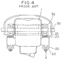
- a caliper 1 interiorly provided with a pad for holding a disk 30 from opposite surfaces thereof is slidably mounted in an axial direction of the disk with respect to a support 32, as shown in Fig. 4, for example USP 4,448,287.
- a pin 2 is slidably inserted into a hole formed in the caliper 1, the pin 2 being screwed into the support 32 secured to a vehicle body.
- These pins 2 are provided on opposite ends of the caliper 1 and support the caliper 1 slidably with respect to the support 32.
- FIG. 4 The construction of the peripheral portion of the dust-proof boot is shown in Fig. 4. That is, the pins 2 are slidably inserted into the caliper 1, and a dust-proof boot 22 is provided between the caliper 1 and the pin 2.
- the dust-proof boot 22 has a bellows portion 23 formed at one end with a mounting portion on the caliper and at the other end with a mounting portion on the pin, the mounting portion on the caliper having an engaging projection projected at a radius angle.
- the engaging projection is fitted into an engaging annular groove provided in the caliper 1, and the pin 2 is inserted into an engaging internal diameter portion whereby the dust-proof boot can be fixed.
- the assembly apparatus is so difficult as to comprise an obstacle to automation.
- the present invention has been achieved in view of the foregoing and provides a technique in which a dust-proof boot can be mounted simply and positively.
- the present invention provides a dust-proof boot for dust-proofing between a support and a pin, inserted into a guide hole of the support, of a disk brake, said boot being made of resilient material and formed as a sleeve having an expansible bellows portion, a first end with an engaging ring for engagement with the pin, and a second end with an internal engaging ring for internal engagement with the guide hole as well as with an external engaging ring for external engagement with the support, characterized in
- a dust-proof boot according to the precharacterizing part of the preceding paragraph is known from US patent no. 4 926 979.
- the invention moreover, provides a method for mounting the dust-proof boot to a support, as described in claim 3.
- the internal engaging ring of the dust-proof boot is fitted into an internal groove of the support, after which compressed air is supplied from the interior of the bellows portion, said compressed air spreading the external engaging ring via the air flow port to fit the external engaging ring into the external groove.
- the dust-proof boot when the internal engaging ring and the external engaging ring are inserted into the support of the caliper, the dust-proof boot is interiorly pressurized so that the external engaging ring is spread by air flown through the air flow port. Therefore, mounting of the external engaging ring to the external groove is easy, the dust-proof boot can be simply and positively mounted and automation of installation thereof becomes easy.
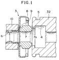
- Fig. 1 is a sectional view showing one embodiment of the present invention.
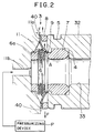
- Fig. 2 is a sectional view of the assembling process showing one embodiment of the present invention.
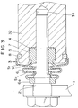
- Fig. 3 is a sectional view of the assembling state showing one embodiment of the present invention.
- Fig. 4 is a plan view of a general disk brake in prior art.
- a dust-proof boot 3 is formed of a resilient material and is arranged between a support 32 and a pin 2 to have a function for preventing dust from entering.
- the support 32 is provided with a guide hole 33.
- the guide hole is formed in an internal wall and an external wall on one end thereof with an annular internal groove 4 and external groove 5 along the peripheral direction.
- the dust-proof boot 3 has an internal engaging ring 7 engaged with the internal groove 4 and an external engaging ring 8 engaged with the external groove 5 extended from one end of a tubular expansible bellows portion 6.
- the internal engaging ring 7 has a damping function of the pin 2 and is formed at the extreme end with a taper 7a.
- the internal engaging ring 7 is formed at its base with an air flow port 9.
- One air flow port 9 will suffice but a plurality of air flow ports may be provided. This air flow port 9 is provided, at one end of the bellows portion 6, at the base on the side of the internal engaging ring 7 from a branch portion of the internal engaging ring 7 and the external engaging ring 8.
- the bellows portion 6 is provided on the other end thereof with a ring portion 6a fixed to the pin 2 extending through the guide hole 33 and the bellows portion 6.
- the first jig receives the bellows portion 6 of the dust-proof boot in an extended state and fixes it in a state where the internal engaging ring 7 and the external engaging ring 8 project from the extreme end thereof.
- the second jig 11 is formed with a communication hole 11b at a position coaxial with the center of the pin 2, and a pressurizing device P is connected to the communication hole 11b. Compressed air can be supplied into the guide hole 33 of the support 32 through the dust-proof boot 3.
- the second jig 11 has a pressing surface 40 substantially equal to an external diameter of the external engaging ring 8 in the spread state.
- the dust-proof boot 3 is moved toward the support 32 in the state where the bellows portion 6 is held within the tubular first jig 10 (Fig. 1).
- the taper 7a of the internal engaging ring 7 is guided by the inner edge of the guide hole 33 of the support 32 and mounted in the internal groove 4 as the first jig moves close thereto (Fig. 2).
- the jig is replaced by the second jig 11. and the external engaging ring 8 is lightly pressed and held between the support 32 and the pressing surface 40 of the second jig. Subsequently, compressed air A is supplied from the pressurizing device P into the dust-proof boot 3 through the communication hole 11b.
- the compressed air A flows into a portion surrounded by the internal engaging ring 7, the external engaging ring 8 and the support 32 through the air flow port 9.
- the external engaging ring 8 held between the support 32 and the second jig 11 is spread by the pressure.
- the second jig 11 is further moved forward toward the support 32 in the state where the external engaging ring 8 is fully spread, the external engaging ring 8 is pressed by the pressing surface 40 of the second jig 11 to climb over the support 32, and the ring 8 is fitted into the external groove 5.
- Fig. 3 shows the state where mounting of the dust-proof boot 3 is completed.
- the air flow port 9 merely extends through a space S1 between the outer peripheral surface of the pin 2 and the bellows portion 6 and a space S2 between the internal surface of the external engaging ring 8 and the end of the support 32, and the interior of the dust-proof boot 3 is isolated from the exterior. Because of this, entry of dust from the exterior is prevented.
Landscapes
- Engineering & Computer Science (AREA)
- General Engineering & Computer Science (AREA)
- Mechanical Engineering (AREA)
- Sealing Devices (AREA)
- Braking Arrangements (AREA)
- Diaphragms And Bellows (AREA)
Description
- The present invention relates to a dust-proof boot for dust-proofing between a pin and a caliper, and a method for mounting the boot.
- In a disk brake of this kind, a caliper 1 interiorly provided with a pad for holding a
disk 30 from opposite surfaces thereof is slidably mounted in an axial direction of the disk with respect to asupport 32, as shown in Fig. 4, for example USP 4,448,287. - A
pin 2 is slidably inserted into a hole formed in the caliper 1, thepin 2 being screwed into thesupport 32 secured to a vehicle body. Thesepins 2 are provided on opposite ends of the caliper 1 and support the caliper 1 slidably with respect to thesupport 32. - The construction of the peripheral portion of the dust-proof boot is shown in Fig. 4. That is, the
pins 2 are slidably inserted into the caliper 1, and a dust-proof boot 22 is provided between the caliper 1 and thepin 2. - The dust-
proof boot 22 has abellows portion 23 formed at one end with a mounting portion on the caliper and at the other end with a mounting portion on the pin, the mounting portion on the caliper having an engaging projection projected at a radius angle. The engaging projection is fitted into an engaging annular groove provided in the caliper 1, and thepin 2 is inserted into an engaging internal diameter portion whereby the dust-proof boot can be fixed. However, in this system, the assembly apparatus is so difficult as to comprise an obstacle to automation. - The present invention has been achieved in view of the foregoing and provides a technique in which a dust-proof boot can be mounted simply and positively.
- For solving the above-described technical problems, the present invention provides a dust-proof boot for dust-proofing between a support and a pin, inserted into a guide hole of the support, of a disk brake, said boot being made of resilient material and formed as a sleeve having an expansible bellows portion, a first end with an engaging ring for engagement with the pin, and a second end with an internal engaging ring for internal engagement with the guide hole as well as with an external engaging ring for external engagement with the support, characterized in
- that the boot branches into an internal branch portion extending to the internal engaging ring and an external branch portion extending to the external engaging ring;
- and that the internal branch portion comprises at least one air flow port allowing the passage of compressed air (A) from the inside of the bellows portion for spreading the external engaging ring when, during the process of mounting the boot to the support, a space is formed confined by the internal branch portion, the external branch portion and the part of the support located between the internal engaging ring and the external engaging ring.
- A dust-proof boot according to the precharacterizing part of the preceding paragraph is known from US patent no. 4 926 979.
- The invention, moreover, provides a method for mounting the dust-proof boot to a support, as described in
claim 3. - In mounting the dust-proof boot on a support provided with a guide hole, the internal engaging ring of the dust-proof boot is fitted into an internal groove of the support, after which compressed air is supplied from the interior of the bellows portion, said compressed air spreading the external engaging ring via the air flow port to fit the external engaging ring into the external groove.
- In the aforementioned arrangement, when the dust-proof boot (bellows portion) is pressurized under the state wherein the internal engaging ring is inserted into the internal groove so that the interior of the guide hole reaches a positive pressure in excess of a predetermined level, pressurized air flows into a portion surrounded by the internal engaging ring, the external engaging ring and the end of the guide hole through the air flow port. The external engaging ring is spread by the pressure and the external engaging ring is completely fitted in the external groove.
- According to the present invention, when the internal engaging ring and the external engaging ring are inserted into the support of the caliper, the dust-proof boot is interiorly pressurized so that the external engaging ring is spread by air flown through the air flow port. Therefore, mounting of the external engaging ring to the external groove is easy, the dust-proof boot can be simply and positively mounted and automation of installation thereof becomes easy.
- Fig. 1 is a sectional view showing one embodiment of the present invention.
- Fig. 2 is a sectional view of the assembling process showing one embodiment of the present invention.
- Fig. 3 is a sectional view of the assembling state showing one embodiment of the present invention.
- Fig. 4 is a plan view of a general disk brake in prior art.
- An embodiment of the present invention will be described hereinbelow with reference to Figs. 1 to 3.
- A dust-
proof boot 3 is formed of a resilient material and is arranged between asupport 32 and apin 2 to have a function for preventing dust from entering. - The
support 32 is provided with aguide hole 33. The guide hole is formed in an internal wall and an external wall on one end thereof with an annularinternal groove 4 andexternal groove 5 along the peripheral direction. - The dust-
proof boot 3 has an internal engagingring 7 engaged with theinternal groove 4 and an externalengaging ring 8 engaged with theexternal groove 5 extended from one end of a tubularexpansible bellows portion 6. The internalengaging ring 7 has a damping function of thepin 2 and is formed at the extreme end with a taper 7a. The internalengaging ring 7 is formed at its base with anair flow port 9. Oneair flow port 9 will suffice but a plurality of air flow ports may be provided. Thisair flow port 9 is provided, at one end of thebellows portion 6, at the base on the side of the internalengaging ring 7 from a branch portion of the internalengaging ring 7 and the externalengaging ring 8. - The
bellows portion 6 is provided on the other end thereof with aring portion 6a fixed to thepin 2 extending through theguide hole 33 and thebellows portion 6. - In mounting the dust-
proof boot 3, a tubularfirst jig 10 and a second jig 11 for replacing in the process are used. - As shown in Fig. 1, the first jig receives the
bellows portion 6 of the dust-proof boot in an extended state and fixes it in a state where the internalengaging ring 7 and the externalengaging ring 8 project from the extreme end thereof. - As shown in Fig. 2, the second jig 11 is formed with a communication hole 11b at a position coaxial with the center of the
pin 2, and a pressurizing device P is connected to the communication hole 11b. Compressed air can be supplied into theguide hole 33 of thesupport 32 through the dust-proof boot 3. The second jig 11 has apressing surface 40 substantially equal to an external diameter of the externalengaging ring 8 in the spread state. - The process for mounting the dust-proof boot will be described hereinbelow.
- The dust-
proof boot 3 is moved toward thesupport 32 in the state where thebellows portion 6 is held within the tubular first jig 10 (Fig. 1). - The taper 7a of the internal
engaging ring 7 is guided by the inner edge of theguide hole 33 of thesupport 32 and mounted in theinternal groove 4 as the first jig moves close thereto (Fig. 2). - The jig is replaced by the second jig 11. and the external
engaging ring 8 is lightly pressed and held between thesupport 32 and thepressing surface 40 of the second jig. Subsequently, compressed air A is supplied from the pressurizing device P into the dust-proof boot 3 through the communication hole 11b. - The compressed air A flows into a portion surrounded by the internal
engaging ring 7, the externalengaging ring 8 and thesupport 32 through theair flow port 9. The externalengaging ring 8 held between thesupport 32 and the second jig 11 is spread by the pressure. When the second jig 11 is further moved forward toward thesupport 32 in the state where the externalengaging ring 8 is fully spread, the externalengaging ring 8 is pressed by thepressing surface 40 of the second jig 11 to climb over thesupport 32, and thering 8 is fitted into theexternal groove 5. - Fig. 3 shows the state where mounting of the dust-
proof boot 3 is completed. In Fig. 3, theair flow port 9 merely extends through a space S1 between the outer peripheral surface of thepin 2 and thebellows portion 6 and a space S2 between the internal surface of the externalengaging ring 8 and the end of thesupport 32, and the interior of the dust-proof boot 3 is isolated from the exterior. Because of this, entry of dust from the exterior is prevented.
Claims (5)
- Dust-proof boot (3) for dust-proofing between a support (32) and a pin (2), inserted into a guide hole (33) of the support (32), of a disk brake, said boot (3) being made of resilient material and formed as a sleeve having an expansible bellows portion (6), a first end with an engaging ring (6a) for engagement with the pin (2), and a second end with an internal engaging ring (7) for internal engagement with the guide hole (33) as well as with an external engaging ring (8) for external engagement with the support (32),
characterized in- that the boot (3) branches into an internal branch portion extending to the internal engaging ring (7) and an external branch portion extending to the external engaging ring (8);- and that the internal branch portion comprises at least one air flow port (9) allowing the passage of compressed air (A) from the inside of the bellows portion (6) for spreading the external engaging ring (8) when, during the process of mounting the boot (3) to the support (32), a space (S2) is formed confined by the internal branch portion, the external branch portion and the part of the support (32) located between the internal engaging ring (7) and the external engaging ring (8). - Dust-proof boot (3) according to claim 1 wherein the internal engaging ring (7) is formed with a taper (7a) at the extreme end thereof to provide guiding of the internal engaging ring (7) during the mounting process.
- A method for mounting the dust-proof boot (3) of claim 1 or 2 to the support (32), comprising:- fitting the internal engaging ring (7) of the dust-proof boot (3) into an internal groove (4) of the guide hole (33) of the support (32), said support (32) being provided with the internal groove (4) and an external groove (5) in the inner periphery and outer periphery thereof, respectively in the vicinity of the extreme end of the guide hole (33);- and thereafter supplying compressed air (A) from the interior of the bellows portion (6), said compressed air (A) flowing through the at least one air flow port (9) to spread the external engaging ring (8) so that the external engaging ring (8) is fitted into the external groove (5).
- The method according to claim 3, comprising:- moving a first jig (10) close to the support (32) to fit the internal engaging ring (7) into the internal groove (4) of the support (32), said first jig (10) receiving therein the dust-proof boot (3) in the state where the bellows portion (6) is expanded and having the internal engaging ring (7) and the external engaging ring (8) of the dust-proof boot (3) projected from the end thereof;- and thereafter supplying compressed air (A) from the interior of the bellows portion (6), said compressed air (A) flowing into the air flow port (9) to spread the external engaging ring (8), and moving a second jig (11) having a diameter corresponding to the spread external engaging ring (8) close to the support (32), whereby the external engaging ring (8) is caused to climb over the end of the support (32) and fitted into the external groove (5).
- The method of claim 4, comprising:- moving the second jig (11) toward the support (32) for slightly pressing the external engaging ring (8) against the support (32);- thereafter supplying compressed air (A);- and finally moving the second jig (11) further forward, thereby pressing the fully spread external engaging ring (8) onto the support (32) and fitting it into the external groove (5).
Applications Claiming Priority (2)
| Application Number | Priority Date | Filing Date | Title |
|---|---|---|---|
| JP1991020233U JP2527432Y2 (en) | 1991-03-29 | 1991-03-29 | Dust proof boots |
| JP20233/91U | 1991-03-29 |
Publications (2)
| Publication Number | Publication Date |
|---|---|
| EP0506125A1 EP0506125A1 (en) | 1992-09-30 |
| EP0506125B1 true EP0506125B1 (en) | 1996-01-24 |
Family
ID=12021468
Family Applications (1)
| Application Number | Title | Priority Date | Filing Date |
|---|---|---|---|
| EP92105381A Expired - Lifetime EP0506125B1 (en) | 1991-03-29 | 1992-03-27 | Dust-proof boot and method for mounting same |
Country Status (5)
| Country | Link |
|---|---|
| US (1) | US5261678A (en) |
| EP (1) | EP0506125B1 (en) |
| JP (1) | JP2527432Y2 (en) |
| DE (1) | DE69207797T2 (en) |
| ES (1) | ES2082258T3 (en) |
Families Citing this family (13)
| Publication number | Priority date | Publication date | Assignee | Title |
|---|---|---|---|---|
| DE4334170A1 (en) * | 1993-10-07 | 1995-04-13 | Voss Armaturen | Plug-in coupling for pressure medium systems |
| GB2287072B (en) * | 1994-02-24 | 1996-11-27 | Draftex Ind Ltd | Protective bellows |
| DE29801725U1 (en) * | 1998-02-04 | 1998-03-19 | Spedition Kunze GmbH, 76137 Karlsruhe | Bellows mounting tool |
| US6354602B1 (en) | 2000-03-03 | 2002-03-12 | American Axle & Manufacturing, Inc. | Assembly vent for boot/seal installation |
| TW552359B (en) * | 2000-08-31 | 2003-09-11 | Tokico Ltd | Disc brake |
| US7097004B2 (en) * | 2003-01-24 | 2006-08-29 | Akebono Corporation (North America) | Pressure bleeding boot-type seal |
| DE102008034652A1 (en) * | 2008-07-25 | 2010-02-04 | Knorr-Bremse Systeme für Nutzfahrzeuge GmbH | On a guide rail of a disc brake arranged bellows |
| JP5908667B2 (en) * | 2010-02-25 | 2016-04-26 | ザマ・ジャパン株式会社 | Dust-proof seal structure of valve stem in rotary throttle valve type vaporizer |
| EP3779226B2 (en) * | 2019-08-16 | 2025-09-17 | Meritor Heavy Vehicle Braking Systems (UK) Limited | A guide assembly for a disc brake |
| CN211852587U (en) * | 2020-04-01 | 2020-11-03 | 浙江德财制动系统有限公司 | Dust cover for guide sleeve of automobile brake caliper |
| DE102021213186A1 (en) * | 2021-11-23 | 2023-05-25 | Continental Automotive Technologies GmbH | Braking device with an elastic protection device |
| JP7557486B2 (en) * | 2022-02-04 | 2024-09-27 | 株式会社ハイレックスコーポレーション | boots |
| CN120734686B (en) * | 2025-08-25 | 2025-11-18 | 万向钱潮股份公司 | Dust cover press-fitting system and method |
Family Cites Families (13)
| Publication number | Priority date | Publication date | Assignee | Title |
|---|---|---|---|---|
| JPS6049780B2 (en) * | 1978-02-02 | 1985-11-05 | 曙ブレーキ工業株式会社 | Air bleed structure of sliding part of pin slide type disc brake |
| JPS55124093A (en) * | 1979-03-20 | 1980-09-24 | Tokico Ltd | Dust cover device |
| JPS6222679Y2 (en) * | 1980-11-21 | 1987-06-09 | ||
| JPS58142450U (en) * | 1982-03-19 | 1983-09-26 | アイシン精機株式会社 | boots |
| JPS5920031U (en) * | 1982-07-28 | 1984-02-07 | トヨタ自動車株式会社 | Pin slide movable caliper type disc brake |
| US4508018A (en) * | 1983-07-11 | 1985-04-02 | Thyssen-Bornemisza, Inc. | Boot assembly for brake actuator |
| BR8402890A (en) * | 1983-07-22 | 1985-06-11 | Teves Gmbh Alfred | SEAL COVER FOR CYLINDRICAL PARTS, ESPECIALLY FOR POINT ACTION DISK BRAKE GUIDE |
| JPS60180832U (en) * | 1984-05-10 | 1985-11-30 | アイシン精機株式会社 | Protective structure of pin boots in pin slide type disc brakes |
| JPS60180831U (en) * | 1984-05-10 | 1985-11-30 | アイシン精機株式会社 | Protective structure of pin boots in pin slide type disc brakes |
| US4629641A (en) * | 1984-07-24 | 1986-12-16 | Paullin Dale W | Ventilated boot |
| US4860571A (en) * | 1986-09-26 | 1989-08-29 | Kenneth L. Smedberg | Power press with improved cushioning system |
| DE3633337A1 (en) * | 1986-10-01 | 1988-04-07 | Teves Gmbh Alfred | BOLT AND BOLT DAMPING ELEMENT FOR FLOATING SADDLE PARTIAL DISC BRAKES, ESPECIALLY FOR MOTOR VEHICLES |
| JPH0529537Y2 (en) * | 1988-07-13 | 1993-07-28 |
-
1991
- 1991-03-29 JP JP1991020233U patent/JP2527432Y2/en not_active Expired - Lifetime
-
1992
- 1992-03-27 ES ES92105381T patent/ES2082258T3/en not_active Expired - Lifetime
- 1992-03-27 EP EP92105381A patent/EP0506125B1/en not_active Expired - Lifetime
- 1992-03-27 DE DE69207797T patent/DE69207797T2/en not_active Expired - Fee Related
- 1992-03-30 US US07/860,459 patent/US5261678A/en not_active Expired - Fee Related
Also Published As
| Publication number | Publication date |
|---|---|
| DE69207797D1 (en) | 1996-03-07 |
| ES2082258T3 (en) | 1996-03-16 |
| DE69207797T2 (en) | 1996-09-19 |
| US5261678A (en) | 1993-11-16 |
| JPH04117225U (en) | 1992-10-20 |
| EP0506125A1 (en) | 1992-09-30 |
| JP2527432Y2 (en) | 1997-02-26 |
Similar Documents
| Publication | Publication Date | Title |
|---|---|---|
| EP0506125A1 (en) | Dust-proof boot and method for mounting same | |
| US4685686A (en) | Sealing cap for a bolt guide of a spot-type disc brake | |
| US4639159A (en) | Device for attaching bellows to a cylindrical member | |
| EP0731229A3 (en) | Holding device for shower head | |
| JPS6036603U (en) | Cable connector for automatic connection of at least one of electrical heating conductors and control conductors of a railway vehicle | |
| US5898808A (en) | Multifibre connector plug | |
| US5531013A (en) | Method of and apparatus for assembling work unit | |
| US4389091A (en) | Method and device for connecting optical fibers | |
| US4144952A (en) | Sliding support structure for a disc brake caliper | |
| US5875550A (en) | Steer spindle bullet tool | |
| CA2107652A1 (en) | Slider Assembly for Automotive Brake Caliper | |
| US5299665A (en) | Damping bushing | |
| EP0045300B1 (en) | Equalizer bar support assembly | |
| JPH0762493B2 (en) | Sealing cap and sealing device for cylindrical member | |
| GB2162273A (en) | Device for fixing to a bulkhead the shielding conduit of a control cable | |
| CN118645842A (en) | A multi-degree-of-freedom blind plug-in and pull-off separation device | |
| KR102355129B1 (en) | Apparatus for applying viscous materials | |
| US5457865A (en) | Automatic boot mounting apparatus and method of automatically mounting a boot with the apparatus | |
| JP2002070899A (en) | Disc brake | |
| JPH1116236A (en) | Disk centering and holding device | |
| JP3529001B2 (en) | Mobile equipment mounting device | |
| JP2549881Y2 (en) | Drive shaft | |
| KR100218574B1 (en) | Connection device of high pressure water pipe | |
| JPH0367942B2 (en) | ||
| JPS6018442A (en) | Valve device |
Legal Events
| Date | Code | Title | Description |
|---|---|---|---|
| PUAI | Public reference made under article 153(3) epc to a published international application that has entered the european phase |
Free format text: ORIGINAL CODE: 0009012 |
|
| AK | Designated contracting states |
Kind code of ref document: A1 Designated state(s): DE ES GB |
|
| 17P | Request for examination filed |
Effective date: 19930310 |
|
| 17Q | First examination report despatched |
Effective date: 19931124 |
|
| GRAA | (expected) grant |
Free format text: ORIGINAL CODE: 0009210 |
|
| AK | Designated contracting states |
Kind code of ref document: B1 Designated state(s): DE ES GB |
|
| REF | Corresponds to: |
Ref document number: 69207797 Country of ref document: DE Date of ref document: 19960307 |
|
| REG | Reference to a national code |
Ref country code: ES Ref legal event code: FG2A Ref document number: 2082258 Country of ref document: ES Kind code of ref document: T3 |
|
| PLBE | No opposition filed within time limit |
Free format text: ORIGINAL CODE: 0009261 |
|
| STAA | Information on the status of an ep patent application or granted ep patent |
Free format text: STATUS: NO OPPOSITION FILED WITHIN TIME LIMIT |
|
| 26N | No opposition filed | ||
| PGFP | Annual fee paid to national office [announced via postgrant information from national office to epo] |
Ref country code: ES Payment date: 19990302 Year of fee payment: 8 |
|
| PGFP | Annual fee paid to national office [announced via postgrant information from national office to epo] |
Ref country code: GB Payment date: 19990303 Year of fee payment: 8 |
|
| PGFP | Annual fee paid to national office [announced via postgrant information from national office to epo] |
Ref country code: DE Payment date: 19990521 Year of fee payment: 8 |
|
| PG25 | Lapsed in a contracting state [announced via postgrant information from national office to epo] |
Ref country code: GB Free format text: LAPSE BECAUSE OF NON-PAYMENT OF DUE FEES Effective date: 20000327 |
|
| PG25 | Lapsed in a contracting state [announced via postgrant information from national office to epo] |
Ref country code: ES Free format text: LAPSE BECAUSE OF NON-PAYMENT OF DUE FEES Effective date: 20000328 |
|
| GBPC | Gb: european patent ceased through non-payment of renewal fee |
Effective date: 20000327 |
|
| PG25 | Lapsed in a contracting state [announced via postgrant information from national office to epo] |
Ref country code: DE Free format text: LAPSE BECAUSE OF NON-PAYMENT OF DUE FEES Effective date: 20010103 |
|
| REG | Reference to a national code |
Ref country code: ES Ref legal event code: FD2A Effective date: 20010910 |