EP0505688B1 - Control for the positive displacement machine of a hydrostatic-mechanical gearing shiftable under load - Google Patents
Control for the positive displacement machine of a hydrostatic-mechanical gearing shiftable under load Download PDFInfo
- Publication number
- EP0505688B1 EP0505688B1 EP92101406A EP92101406A EP0505688B1 EP 0505688 B1 EP0505688 B1 EP 0505688B1 EP 92101406 A EP92101406 A EP 92101406A EP 92101406 A EP92101406 A EP 92101406A EP 0505688 B1 EP0505688 B1 EP 0505688B1
- Authority
- EP
- European Patent Office
- Prior art keywords
- volume
- new
- leakage
- gear
- dvold
- Prior art date
- Legal status (The legal status is an assumption and is not a legal conclusion. Google has not performed a legal analysis and makes no representation as to the accuracy of the status listed.)
- Expired - Lifetime
Links
- 238000006073 displacement reaction Methods 0.000 title claims description 32
- 230000005540 biological transmission Effects 0.000 claims description 21
- 230000002706 hydrostatic effect Effects 0.000 claims description 16
- 230000001360 synchronised effect Effects 0.000 claims description 12
- 238000000034 method Methods 0.000 claims description 10
- 230000001276 controlling effect Effects 0.000 claims 1
- 230000001105 regulatory effect Effects 0.000 claims 1
- 239000003921 oil Substances 0.000 description 13
- 150000003839 salts Chemical class 0.000 description 10
- 230000008878 coupling Effects 0.000 description 4
- 238000010168 coupling process Methods 0.000 description 4
- 238000005859 coupling reaction Methods 0.000 description 4
- 239000000654 additive Substances 0.000 description 3
- 230000000996 additive effect Effects 0.000 description 3
- 238000012937 correction Methods 0.000 description 2
- 238000010586 diagram Methods 0.000 description 2
- 230000006978 adaptation Effects 0.000 description 1
- 210000000078 claw Anatomy 0.000 description 1
- 230000001419 dependent effect Effects 0.000 description 1
- 230000000694 effects Effects 0.000 description 1
- 239000010720 hydraulic oil Substances 0.000 description 1
- 230000007935 neutral effect Effects 0.000 description 1
Images

Classifications
-
- F—MECHANICAL ENGINEERING; LIGHTING; HEATING; WEAPONS; BLASTING
- F16—ENGINEERING ELEMENTS AND UNITS; GENERAL MEASURES FOR PRODUCING AND MAINTAINING EFFECTIVE FUNCTIONING OF MACHINES OR INSTALLATIONS; THERMAL INSULATION IN GENERAL
- F16H—GEARING
- F16H61/00—Control functions within control units of change-speed- or reversing-gearings for conveying rotary motion ; Control of exclusively fluid gearing, friction gearing, gearings with endless flexible members or other particular types of gearing
- F16H61/38—Control of exclusively fluid gearing
- F16H61/40—Control of exclusively fluid gearing hydrostatic
- F16H61/46—Automatic regulation in accordance with output requirements
- F16H61/462—Automatic regulation in accordance with output requirements for achieving a target speed ratio
-
- F—MECHANICAL ENGINEERING; LIGHTING; HEATING; WEAPONS; BLASTING
- F16—ENGINEERING ELEMENTS AND UNITS; GENERAL MEASURES FOR PRODUCING AND MAINTAINING EFFECTIVE FUNCTIONING OF MACHINES OR INSTALLATIONS; THERMAL INSULATION IN GENERAL
- F16H—GEARING
- F16H47/00—Combinations of mechanical gearing with fluid clutches or fluid gearing
- F16H47/02—Combinations of mechanical gearing with fluid clutches or fluid gearing the fluid gearing being of the volumetric type
- F16H47/04—Combinations of mechanical gearing with fluid clutches or fluid gearing the fluid gearing being of the volumetric type the mechanical gearing being of the type with members having orbital motion
-
- F—MECHANICAL ENGINEERING; LIGHTING; HEATING; WEAPONS; BLASTING
- F16—ENGINEERING ELEMENTS AND UNITS; GENERAL MEASURES FOR PRODUCING AND MAINTAINING EFFECTIVE FUNCTIONING OF MACHINES OR INSTALLATIONS; THERMAL INSULATION IN GENERAL
- F16H—GEARING
- F16H61/00—Control functions within control units of change-speed- or reversing-gearings for conveying rotary motion ; Control of exclusively fluid gearing, friction gearing, gearings with endless flexible members or other particular types of gearing
- F16H61/38—Control of exclusively fluid gearing
- F16H61/40—Control of exclusively fluid gearing hydrostatic
- F16H61/46—Automatic regulation in accordance with output requirements
-
- F—MECHANICAL ENGINEERING; LIGHTING; HEATING; WEAPONS; BLASTING
- F16—ENGINEERING ELEMENTS AND UNITS; GENERAL MEASURES FOR PRODUCING AND MAINTAINING EFFECTIVE FUNCTIONING OF MACHINES OR INSTALLATIONS; THERMAL INSULATION IN GENERAL
- F16H—GEARING
- F16H37/00—Combinations of mechanical gearings, not provided for in groups F16H1/00 - F16H35/00
- F16H37/02—Combinations of mechanical gearings, not provided for in groups F16H1/00 - F16H35/00 comprising essentially only toothed or friction gearings
- F16H37/06—Combinations of mechanical gearings, not provided for in groups F16H1/00 - F16H35/00 comprising essentially only toothed or friction gearings with a plurality of driving or driven shafts; with arrangements for dividing torque between two or more intermediate shafts
- F16H37/08—Combinations of mechanical gearings, not provided for in groups F16H1/00 - F16H35/00 comprising essentially only toothed or friction gearings with a plurality of driving or driven shafts; with arrangements for dividing torque between two or more intermediate shafts with differential gearing
- F16H37/0833—Combinations of mechanical gearings, not provided for in groups F16H1/00 - F16H35/00 comprising essentially only toothed or friction gearings with a plurality of driving or driven shafts; with arrangements for dividing torque between two or more intermediate shafts with differential gearing with arrangements for dividing torque between two or more intermediate shafts, i.e. with two or more internal power paths
- F16H37/084—Combinations of mechanical gearings, not provided for in groups F16H1/00 - F16H35/00 comprising essentially only toothed or friction gearings with a plurality of driving or driven shafts; with arrangements for dividing torque between two or more intermediate shafts with differential gearing with arrangements for dividing torque between two or more intermediate shafts, i.e. with two or more internal power paths at least one power path being a continuously variable transmission, i.e. CVT
- F16H2037/088—Power split variators with summing differentials, with the input of the CVT connected or connectable to the input shaft
- F16H2037/0886—Power split variators with summing differentials, with the input of the CVT connected or connectable to the input shaft with switching means, e.g. to change ranges
-
- Y—GENERAL TAGGING OF NEW TECHNOLOGICAL DEVELOPMENTS; GENERAL TAGGING OF CROSS-SECTIONAL TECHNOLOGIES SPANNING OVER SEVERAL SECTIONS OF THE IPC; TECHNICAL SUBJECTS COVERED BY FORMER USPC CROSS-REFERENCE ART COLLECTIONS [XRACs] AND DIGESTS
- Y10—TECHNICAL SUBJECTS COVERED BY FORMER USPC
- Y10T—TECHNICAL SUBJECTS COVERED BY FORMER US CLASSIFICATION
- Y10T74/00—Machine element or mechanism
- Y10T74/19—Gearing
- Y10T74/19149—Gearing with fluid drive
-
- Y—GENERAL TAGGING OF NEW TECHNOLOGICAL DEVELOPMENTS; GENERAL TAGGING OF CROSS-SECTIONAL TECHNOLOGIES SPANNING OVER SEVERAL SECTIONS OF THE IPC; TECHNICAL SUBJECTS COVERED BY FORMER USPC CROSS-REFERENCE ART COLLECTIONS [XRACs] AND DIGESTS
- Y10—TECHNICAL SUBJECTS COVERED BY FORMER USPC
- Y10T—TECHNICAL SUBJECTS COVERED BY FORMER US CLASSIFICATION
- Y10T74/00—Machine element or mechanism
- Y10T74/19—Gearing
- Y10T74/19555—Varying speed ratio
Definitions
- the invention relates to a method for controlling a hydrostatic variable transmission of a hydrostatic-mechanically stepless power-split power shift transmission in which a displacement volume is actuated after switching on a clutch of a new gear, taking into account a leakage volume with regard to a theoretical displacement volume, after which the clutch of the still active, previously effective Ganges is separated.
- the solution to the problem is that the new displacement volume is determined in each case from the old leakage volume in accordance with different hydraulic pressure ratios in the adjusting gear before and after the switching operation, the setting of the new displacement volume with respect to the theoretical displacement volume taking place according to a new leakage volume that corresponds to the hydraulic pressure ratios is determined accordingly from the old leak volume.
- the displacement volume is carried out by means of a swivel adjustment of an abutment, which is carried out in an electrically controlled manner by means of a proportional hydraulic adjusting device.
- the positive displacement machine is used in an additive manner to transmit power before shifting up a gear stage and subtractively after shifting into higher gear.
- theoretically synchronous speeds are specified on the clutches to be engaged and disengaged so that the clutch of the new gear is switched on smoothly and the clutch of the previous gear is disengaged smoothly thereafter.
- the hydrostatic transmission is controlled in such a way that the leakage losses are covered before the new gear is engaged to produce synchronous operation on the clutch.
- the swashplate setting which determines the displacement volume, is not made symmetrically to the neutral position, but with different correction angles that are adapted to the respective relative leakage losses and balance them out.
- the power flow in the hydrostatic system changes from additive power when changing gear (the adjustment unit is the pump and the constant unit is the motor) to reactive power (the constant unit is the pump and the adjustment unit is the motor).
- the high and low pressure change between the two connecting lines of the units and the high pressure theoretically increases by the factor of the ratio of the gears.
- the high pressure and the amount of leakage oil in the hydrostatic assembly are approximately proportional to one another.
- a constant leakage oil change factor k can therefore be assumed for each load.
- the setting must be such that the new displacer volume increases equal to the theoretical displacer volume by its product with the leakage oil change factor minus the old displacer volume multiplied by the leakage oil change factor, i.e. the formula
- the setting must be such that the new displacer volume increases equal to the theoretical displacer volume by its quotient with the leakage oil change factor minus the quotient of the old displacement volume with the leakage oil change factor, ie the formula:
- the actual position signals which are obtained during upshifting and downshifting in synchronous states and are used for engaging, and whose values are stored, also include the actual positions for decoupling the same coupling, provided that the same load conditions exist.
- Advantageous consideration of changes in the leakage conditions during operation is achieved in that any differences between an actual signal newly acquired in the synchronous case and the corresponding previously obtained actual signal are always determined and the distance from the optimal new target value is derived directly therefrom with a conversion factor. Signal to the old target signal is calculated.
- This control also provides an adaptation to the leak behavior of the device, which changes with ongoing operation, which is dependent on the temperature of the hydraulic oil and the actuating unit and which changes with the load.
- the determination of the leakage oil losses at the beginning of each switching operation and the pre-calculation of the losses after the operation and taking them into account when determining the setpoint automatically includes all ongoing changes in the operating conditions.
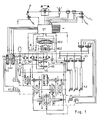
- Fig. 1 shows a hydrostatic-mechanical power split power shift transmission, the hydrostatic branch of which consists of the hydrostatic actuator (HG).
- HG hydrostatic actuator
- ST electronic control device
- HGZ position-proportional hydraulic control cylinder
- HV electric-hydraulic control valve pair
- the presence of this speed ratio is determined from the signals from the speed sensors (S1, S2) in the electronic control device (ST). is determined, actuated by the control device (ST), the electrohydraulic third-gear valve (V3), which hydraulically engages the third-gear clutch (K3), the determined speed ratio ensuring that the transmission parts of the clutch (K3) third gear before synchronizing.
- the proportional device (HGZ) is acted upon by the control device (ST) via the electrohydraulic control valve (HGV) in such a way that this is corrected in accordance with the new leakage losses, so that no torque is transmitted to the coupling clutch claws of the clutch (K2) of the second gear transmission becomes.
- the control device (ST) switches off the second-gear valve (V2) and thereby disengages the second-gear clutch (K2) hydraulically without jerking by switching off the associated controllable valve (V2).
- Fig. 3 shows the pressure conditions in the hydrostatic branch.
- the pressures (P1) and (P2) on both sides of the switching point are related to each other like the control ratio.
- the proportional valve unit For the exact adjustability of the proportional valve unit (HGV), it is fed with a predeterminable current from the control device (ST).
- This current is preferably reported back to the control device (ST) by a current sensor (IS), so that the current strength reported in the presence of synchronous conditions on a clutch to be closed can be stored there as a value of the position signal because of its proportionality and can later be evaluated as a default value.
- IS current sensor
- a position indicator e.g. of a potentiometer (P) on the wiper side
- the dependence of the displacer volume and the associated positions of the control is schematic, ie enlarged in the switching range represented by the displacer volume when shifting up.
- the old displacer volume (Valt) is larger than the theoretical displacer volume (Vth) by the leakage volume (DValt).
- the new displacer volume (Vneu), in which the old gearbox is load-free, is smaller by a leakage volume difference (DValt xk) than the theoretical displacer volume (Vth) by the leakage volume factor (k). Accordingly, the old and new settings (Salt, Sneu) are higher and lower than the theoretical position (Sth) by a smaller or a larger amount.
- the leakage volume factor is in principle greater than 1, since different pressure conditions prevail in the old and new condition, which lead to the differences. As you can see, this gives the formula (1).
- the leakage conditions change during operation, i.e. with different loads, e.g. with train or push operation, i.e. during braking, and can change with the temperature
- the respective values of the position sensor signal (Salt, Salt ') which are present in the synchronous case with only one clutch engaged, are stored as the set position signals to be specified for the setting control, so that the upshift signal (Salt) serves as the target signal (Sneu ') when downshifting and the signal (Salt') when downshifting serves as the target signal (Sneu) when upshifting.
- a target signal specification which adapts even further to changing conditions is achieved when a determined synchronous position (Salt, Salt ') is related to the corresponding stored previous synchronized position (Sg, Sg') and by means of the relationship via the leakage volume factor k the associated new one Decoupling position (Sneu, Sneu ') is calculated from the stored uncoupling position (Sg, Sg').
Landscapes
- Engineering & Computer Science (AREA)
- General Engineering & Computer Science (AREA)
- Mechanical Engineering (AREA)
- Control Of Transmission Device (AREA)
Description
Die Erfindung betrifft ein Verfahren zur Steuerung eines hydrostatischen Verstellgetriebes eines hydrostatischmechanisch stufenlos leistungsverzweigten Lastschaltgetriebes bei dem ein Verdrängervolumen jeweils nach dem Einschalten einer Kupplung eines neuen Ganges, ein Leckvolumen bezüglich eines theoretischen Verdrängervolumens berücksichtigend, angesteuert wird, wonach die Kupplung des jeweils noch mitlaufenden, vorher wirksamen Ganges getrennt wird.The invention relates to a method for controlling a hydrostatic variable transmission of a hydrostatic-mechanically stepless power-split power shift transmission in which a displacement volume is actuated after switching on a clutch of a new gear, taking into account a leakage volume with regard to a theoretical displacement volume, after which the clutch of the still active, previously effective Ganges is separated.
Aus der DE-C-38 38 767 ist eine derartige Steuerung einer Verdrängermaschine bekannt, bei der jeweils beim Gangwechsel eine Einstellung des Verdrängervolumens entsprechend dem theoretischen Ölbedarf zuzüglich eines bestimmten Leckageverlustes erfolgt, damit jeweils die auszurückende Kupplung des vorherigen Ganges möglichst drehmomentlos zu schalten ist. Die Bestimmung eines zu berücksichtigenden Leckageverlustes stellt einen sehr ungenauen Kompromiß dar, da die Verdrängermaschine vor und nach den Schaltpunkten aufeinanderfolgender Getriebestufen jeweils entsprechend der Getriebestufung mit einem unterschiedlichen hydraulischen Übertragungsanteil wirksam ist, so daß die hydraulischen Druckverhältnisse und demzufolge das Verhältnis der Leckageverluste demgemäß unterschiedlich groß ist, was unberückischtigt geblieben ist, so daß das beabsichtigte drehmomentarme Ausrückenden der Kupplungsteile entweder in keinem Fall oder nur bei dem Hoch- oder dem Herunterschalten erreicht wird, was zu Schäden an der Kupplung und dem Getriebe und ruckartigem Betrieb führt.Such a control of a displacement machine is known from DE-C-38 38 767, in which each time the gear is changed, the displacement volume is adjusted according to the theoretical oil requirement plus a certain loss of leakage, so that the clutch to be disengaged from the previous gear is to be switched as torque-free as possible. The determination of a leakage loss to be taken into account represents a very imprecise compromise, since the positive displacement machine before and after the switching points of successive gear stages is effective in accordance with the gear stage with a different hydraulic transmission component, so that the hydraulic pressure ratios and consequently the ratio of the leakage losses are accordingly different , which has remained unadjusted so that the intended low torque disengagement of the clutch parts is either never achieved or only at up or down shift, resulting in damage to the clutch and transmission and jerky operation.
Es ist Aufgabe der Erfindung, eine Steuerung der Verdrängermaschine zu offenbaren, bei der bei jedem Schaltvorgang eine drehmomentlose Einstellung der auszurückenden Kupplungsteile erreicht wird, sowie eine Steuervorrichtung dazu anzugeben.It is an object of the invention to disclose a control of the displacement machine, in which a torque-free adjustment of the clutch parts to be disengaged is achieved with each shift, and to specify a control device therefor.
Die Lösung der Aufgabe besteht darin, daß jeweils aus dem alten Leckvolumen das neue Verdrängervolumen entsprechend unterschiedlicher Hydraulikdruckverhältnisse in dem Verstellgetriebe jeweils vor und nach dem Schaltvorgang bestimmt wird, wobei die Einstellung des neuen Verdrängervolumens bezüglich des theoretischen Verdrängevolumens gemäß einem neuen Leckvolumen erfolgt, das den Hydraulikdruckverhältnissen entsprechend aus dem alten Leckvolumen bestimmt wird.The solution to the problem is that the new displacement volume is determined in each case from the old leakage volume in accordance with different hydraulic pressure ratios in the adjusting gear before and after the switching operation, the setting of the new displacement volume with respect to the theoretical displacement volume taking place according to a new leakage volume that corresponds to the hydraulic pressure ratios is determined accordingly from the old leak volume.
Vorteilhafte Ausgestaltung sind in den Unteransprüchen angegeben.An advantageous embodiment is specified in the subclaims.
Bei den bekannten Verdrängermaschinen wird das Verdrängervolumen durch eine Schwenkverstellung eines Widerlagers vorgenommen, die mittels einer proportional wirkenden hydraulischen Verstelleinrichtung elektrisch gesteuert erfolgt. In einem stufenlosen, hydrostatischleistungsverzweigten Getriebe wird die Verdrängermaschine jeweils vor dem Heraufschalten einer Getriebestufe additiv leistungsübertragend und nach dem Umschalten in den höheren Gang subtraktiv genutzt. In beiden Fällen sind theoretisch synchrone Drehzahlen an den ein- und auszurückenden Kupplungen vorgegeben, damit ein ruckfreies Einschalten der Kupplung des neuen Ganges ebenso wie ein ruckfreies Ausrücken der Kupplung des vorherigen Ganges danach erfolgt. Im praktischen Betrieb ist es nun erforderlich, daß vor dem Einkuppeln des neuen Ganges zur Herstellung des Synchronlaufes an der Kupplung das hydrostatische Getriebe so gesteuert ist, daß auch dessen Leckageverluste gedeckt sind. Da nach dem Einschalten des neuen Ganges wegen der inversen Betriebsweise des Hydraulikgetriebes wieder Leckageverluste bezüglich der konstant arbeitenden Verdrängereinheit auftreten, ist es zur Einstellung einer Drehmomentfreiheit an der auszurückenden Kupplung erforderlich, eine korrigierende, diese Verhältnisse berücksichtigende, Umsteuerung des Verdrängervolumens vorzunehmen, wobei die unterschiedlichen Leckageverluste zu berücksichtigen sind. Gemäß der Erfindung wird bei der Bestimmung dieser korrigierenden Einstellung berücksichtigt, daß die Druckverhältnisse und damit die Leckageverluste jeweils abhängig von dem jeweils genutzten Verzweigungsverhältnis im oberen Drehzahlbereich des unteren Ganges und in unteren Drehzahlbereich des oberen Ganges um das Schaltverhältnis verschieden ist. Aus diesem Grund sind die Leckageverluste vor einem Heraufschalten im Synchronzustand der einzuschaltenden Kupplung kleiner als nach dem Heraufschalten bei einer Einstellung zu einer Drehmomentenfreiheit der auszurückenden Kupplung. Bei einem Herunterschalten sind die Verlustverhältnisse umgekehrt. Gemäß der Erfindung werden diese Unterschiede der Leckageverluste vor und nach dem Schalten in der Einstellung des Verdrängervolumens berücksichtigt, so daß erst dann ein Auskuppeln vorgenommen wird, wenn kein Drehmoment über die Kupplungsteile übertragen wird.In the known displacement machines, the displacement volume is carried out by means of a swivel adjustment of an abutment, which is carried out in an electrically controlled manner by means of a proportional hydraulic adjusting device. In a continuously variable, hydrostatic power-split transmission, the positive displacement machine is used in an additive manner to transmit power before shifting up a gear stage and subtractively after shifting into higher gear. In both cases, theoretically synchronous speeds are specified on the clutches to be engaged and disengaged so that the clutch of the new gear is switched on smoothly and the clutch of the previous gear is disengaged smoothly thereafter. In practical operation, it is now necessary that the hydrostatic transmission is controlled in such a way that the leakage losses are covered before the new gear is engaged to produce synchronous operation on the clutch. Since after switching on the new gear due to the inverse mode of operation of the hydraulic transmission there are again leakage losses with respect to the constantly operating displacement unit, in order to set a torque-free position on the clutch to be disengaged, it is necessary to carry out a corrective, taking into account these conditions, reversing the displacement volume, the different leakage losses are to be considered. According to the invention, when determining this corrective setting, it is taken into account that the pressure ratios and thus the leakage losses each differ depending on the branching ratio used in the upper speed range of the lower gear and in the lower speed range of the upper gear by the switching ratio. For this reason, the leakage losses before an upshift in the synchronous state of the clutch to be engaged are smaller than after an upshift when the clutch is disengaged. When shifting down, the loss ratios are reversed. According to the invention, these differences in leakage losses before and after switching are taken into account in the setting of the displacer volume, so that disengagement is only carried out when no torque is transmitted via the coupling parts.
Um diese Leckagenunterschiede vor und nach dem Einkoppeln und der damit verbundenen Umkehr der Wirkung des hydraulischen Getriebezweiges zu berücksichtigen, wird die Schrägscheibeneinstellung, die das Verdrängervolumen bestimmt, jeweils nicht symmetrisch zur Neutrallage vorgenommen, sondern mit unterschiedlichen Korrekturwinkeln, die an die jeweiligen relativen Leckverluste angepaßt sind und diese ausgleichen.In order to take into account these leakage differences before and after the coupling and the associated reversal of the effect of the hydraulic transmission branch, the swashplate setting, which determines the displacement volume, is not made symmetrically to the neutral position, but with different correction angles that are adapted to the respective relative leakage losses and balance them out.
Die Verhältnisse der Korrekturen der Verdrängereinstellungen ergben sich auf folgende Weise:The ratio of the corrections to the displacer settings is as follows:
Beim Hochschalten wechselt der Leistungsfluß in der Hydrostatik beim Gangwechsel von additiver Leistung (die Verstelleinheit ist die Pumpe und die Konstanteinheit ist der Motor) zur Blindleistung (die Konstanteinheit ist die Pumpe und die Verstelleinheit ist der Motor). Dabei wechseln der Hoch- und der Niederdruck den beiden Verbindungsleitungen der Einheiten und der Hochdruck steigt theoretisch um den Faktor des Stellverhältnisses der Gänge an.When shifting up, the power flow in the hydrostatic system changes from additive power when changing gear (the adjustment unit is the pump and the constant unit is the motor) to reactive power (the constant unit is the pump and the adjustment unit is the motor). The high and low pressure change between the two connecting lines of the units and the high pressure theoretically increases by the factor of the ratio of the gears.
Der Hochdruck und die Leckölmenge in der Hydrostatikbaugruppe stehen annähernd in einem proportionalen Verhalten zueinander. Es kann daher bei jeder Belastung von einem konstanten Lecköländerungsfaktor k ausgegangen werden.The high pressure and the amount of leakage oil in the hydrostatic assembly are approximately proportional to one another. A constant leakage oil change factor k can therefore be assumed for each load.
Daraus ergibt sich, daß nach einem Hochschalten zur Erfüllung der gestellten Bedingung die Einstellung so sein muß, daß das neue Verdrängervolumen gleich dem theoretischen Verdrängervolumen erhöht um dessen Produkt mit dem Lecköländerungsfaktor abzüglich des alten Verdrängervolumens multipliziert mit dem Lecköländrungsfaktors, d.i. die FormelThis means that after an upshift to meet the set condition, the setting must be such that the new displacer volume increases equal to the theoretical displacer volume by its product with the leakage oil change factor minus the old displacer volume multiplied by the leakage oil change factor, i.e. the formula
![]()
![]()
Beim Herunterschalten wechselt der Leistungsfluß in der Hydrostatikbaugruppe beim Gangwechsel von Blindleistung zu additiver Leistung. Dabei wechselt der Hochdruck und der Niederdruck in den Verbindungsleitungen der Hydraulikeinheiten, und der Hochdruck sinkt theoretisch um den Faktor des Stellverhältnisses der Gänge. Wegen der annähernden Proportionalität zwischen dem Druck und dem Leckölverlust in der Hydrostatikbaugruppe kann auch hier von dem konstanten Lecköländerungsfaktor k ausgegangen werden.When shifting down, the power flow in the hydrostatic assembly changes from reactive power to additive power when changing gear. The high pressure and low pressure in the connecting lines of the hydraulic units change, and the high pressure theoretically drops by the factor of the ratio of the gears. Because of the approximate proportionality between the pressure and the leakage oil loss in the hydrostatic assembly, the constant leakage oil change factor k can also be assumed here.
Daraus ergibt sich, da nach dem Herunterschalten zur Erfüllung der gestellten Bedingung die Einstellung so sein muß, daß das neue Verdrängervolumen gleich dem theoretischen Verdrängervolumen erhöht um dessen Quotienten mit dem Lecköländerungsfaktor abzüglich des Quotienten des alten Verdrängungsvolumens mit dem Lecköländerungsfaktor, d.i. die Formel:![]()
![]()
Der Lecköländerungsfaktor kann experimentell gewonnen werden. Er ist prinzipiell größer 1. Er liegt gewöhnlich zwischen 1,5 und 2,5. In einem Getriebe mit einem Stellverhältnis von 1,66 wurde k = 2 als praktisch brauchbar ermittelt.The leakage oil change factor can be obtained experimentally. In principle, it is larger than 1. It is usually between 1.5 and 2.5. In a gearbox with a ratio of 1.66, k = 2 was determined to be practically usable.
Es ist vorteilhaft vorgesehen, zur Einstellung des Verdrängervolumens einen Regelkreis zu verwenden, dem ein Stellungssignal der Stellvorrichtung als Ist-Signal zugeführt wird. Weiterhin ist vorgesehen, daß in bekannter Weise Drehzahlsignale von den An- und Abtriebswellen der hydrostatischen Getriebeeinheit abgenommen werden. Dadurch läßt sich durch Beachtung der jeweils für die einzelnen Gänge bekannten Drehzahlverhältnisse erreichen, daß das Einkuppeln des nächten gewünschten Ganges bei einer Synchronität an der Kupplung erfolgt. Hierbei wird das jeweilige alte Ist-Stellungssignal gewonnen, dessen Größe sich aus dem theoretischen Verdängervolumen und dem alten Leckölverlust ergibt. Zusammen mit dem theoretischen Ist -Stellungssignal wird nun ein der Regelung vorzugebendes neues Soll-Stellungssignal so gebildet wird, daß die neuen Leckölverluste berücksichtigt sind, Wenn danach der so eingeleitete Regelvorgang abgeschlossen ist, wird die Kupplung des früheren Ganges ausgerückt und nun der Gang weiter durchlaufen, indem das Verdrängervolumen weiter verändert vorgegeben wird.It is advantageously provided to use a control circuit for setting the displacement volume, to which a position signal of the actuating device is fed as an actual signal. It is further provided that speed signals are taken from the input and output shafts of the hydrostatic transmission unit in a known manner. As a result, by observing the speed ratios known for the individual gears, the engagement of the next desired gear takes place with synchronism on the clutch. The respective old actual position signal is obtained, the size of which results from the theoretical displacement volume and the old leakage oil loss. Together with the theoretical actual position signal, a new set position signal to be specified for the control is formed in such a way that the new leakage oil losses are taken into account. When the control process initiated in this way is then completed, the clutch of the previous gear is disengaged and the gear is now continued to run by specifying the displacer volume further changed.
In der Praxis ist es nicht erforderlich, die theoretisch verlustfreie Stellung zu kennen, da die Ist-Stellungssignale, die beim Hochschalten und die beim Herunterschalten bei den Synchronzuständen gewonnen werden und zum Einkuppeln dienen, und deren Werte gespeichert werden, jeweils auch die Ist-Stellungen für das Entkuppeln der gleichen Kupplung sind, soweit die gleichen Lastverhältnisse vorliegen. Eine vorteilhafte Berücksichtigung von Änderungen der Leckverhältnisse im laufenden Betrieb wird dadurch erreicht, daß eine etwaige Differenzen eines im Synchronfall neu gewonnenen Ist-Signales zu dem entsprechenden früher gewonnenen Ist-Signal stets ermittelt wird und daraus unmittelbar mit einem Umrechnungsfaktor der Abstand des optimalen neuen Soll-Signals zum alten Soll- Signal errechnet wird.In practice, it is not necessary to know the theoretically loss-free position, since the actual position signals, which are obtained during upshifting and downshifting in synchronous states and are used for engaging, and whose values are stored, also include the actual positions for decoupling the same coupling, provided that the same load conditions exist. Advantageous consideration of changes in the leakage conditions during operation is achieved in that any differences between an actual signal newly acquired in the synchronous case and the corresponding previously obtained actual signal are always determined and the distance from the optimal new target value is derived directly therefrom with a conversion factor. Signal to the old target signal is calculated.
Diese Steuerung erbringt auch eine Anpassung an die sich mit dem laufenden Betrieb verändernden Leckverhalten der Vorrichtung, das der Temperatur des Hydrauliköles und der Stelleinheit abhängig ist und sich mit der Last ändert. Die Bestimmung der Leckölverluste zu Beginn jedes Schaltvorganges und die Vorausberechnung der Verluste nach dem Vorgang und deren Berücksichtigung bei der Sollwertbestimmung schließt automatisch alle laufenden Änderungen der Betriebsverhältnisse ein.This control also provides an adaptation to the leak behavior of the device, which changes with ongoing operation, which is dependent on the temperature of the hydraulic oil and the actuating unit and which changes with the load. The determination of the leakage oil losses at the beginning of each switching operation and the pre-calculation of the losses after the operation and taking them into account when determining the setpoint automatically includes all ongoing changes in the operating conditions.
Eine vorteilhafte Ausgestaltung eines Getriebes mit der Stellvorrichtung, die eine erfindungsgemäße Einstellung und Kupplungsbetätigung vornimmt, zeigen Fig. 1 bis 3.
- Fig. 1 zeigt ein Mehrganggetriebeschema;
- Fig. 2 zeigt die hydrostatischen Leistungsanteile des Getriebes;
- Fig. 3 zeigt die hydrostatischen Druckverhältnisse des Getriebes;
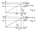
- Fig. 4 zeigt ein Hochschalt-Einstelldiagramm;
- Fig. 5 zeigt ein Herunterschalt-Einstelldiagramm.
- Fig. 1 shows a multi-speed transmission scheme;
- Fig. 2 shows the hydrostatic power components of the transmission;
- Fig. 3 shows the hydrostatic pressure conditions of the transmission;
- Fig. 4 shows an upshift setting diagram;
- 5 shows a downshift setting diagram.
Fig. 1 zeigt ein hydrostatisch-mechanisch leistungsverzweigtes Lastschaltgetriebe, dessen hydrostatischer Zweig aus dem hydrostatischen Stellgetriebe (HG) besteht. Dieses wird durch eine elektronische Steuervorrichtung (ST) gesteuert, indem diese über ein elektrisch-hydraulisches Steuerventilpaar (HGV) einen stellungsproportional wirkenden Hydraulik-Steuerzylinder (HGZ) betätigt, so daß dieser den Stellwinkel und damit das Verdrängervolumen des Hydraulikstellgetriebes (HG) bestimmt.Fig. 1 shows a hydrostatic-mechanical power split power shift transmission, the hydrostatic branch of which consists of the hydrostatic actuator (HG). This is controlled by an electronic control device (ST) by actuating a position-proportional hydraulic control cylinder (HGZ) via an electric-hydraulic control valve pair (HGV), so that it determines the setting angle and thus the displacement volume of the hydraulic control gear (HG).
Beispielsweise wird zum Heraufschalten vom 2. in den 3. Gang bei einem vorgegebenen Drehzahlverhältnis an der Ein- und der Ausgangswelle des Hydrostatikwandlers (HG), das Vorhandensein dieses Drehzahlverhältnisses aus den Signalen der Drehzahlsensoren (S1 , S2) in der elektronischen Steuervorrichtung (ST) ermitteltwird, von der Steuervorrichtung (ST) das elektrohydraulische Dritte-Gang-Ventil (V3) betätigt, das die 3.-Gang-Kupplung (K3) hydraulisch einrücken läßt, wobei das ermittelte Drehzahlverhältnis sicherstellt, daß die Getriebeteile der Kupplung (K3) des dritten Ganges vor dem Kuppeln synchron umlaufen. Dann wird von der Steuervorrichtung (ST) über das elektrohydraulische Steuerventil (HGV) das Proportionalsteuerventil (HGZ) so beaufschlagt, daß dieses den neuen Leckageverlusten gemäß korrigierend verstellt wird, so daß an den mitlaufenden Kuppplungsklauen der Kupplung (K2) des zweiten Ganggetriebes kein Drehmoment übertragen wird. Dann wird von der Steuervorrichtung (ST) das Zweite-Gang-Ventil (V2) abgeschaltet und dadurch die Zweite-Gang-Kupplung (K2) hydraulisch rucklos ausgerückt, indem das zugehörige steuerbare Ventil (V2) abgeschaltet wird.For example, to shift up from 2nd to 3rd gear at a predetermined speed ratio on the input and output shaft of the hydrostatic converter (HG), the presence of this speed ratio is determined from the signals from the speed sensors (S1, S2) in the electronic control device (ST). is determined, actuated by the control device (ST), the electrohydraulic third-gear valve (V3), which hydraulically engages the third-gear clutch (K3), the determined speed ratio ensuring that the transmission parts of the clutch (K3) third gear before synchronizing. Then the proportional device (HGZ) is acted upon by the control device (ST) via the electrohydraulic control valve (HGV) in such a way that this is corrected in accordance with the new leakage losses, so that no torque is transmitted to the coupling clutch claws of the clutch (K2) of the second gear transmission becomes. Then the control device (ST) switches off the second-gear valve (V2) and thereby disengages the second-gear clutch (K2) hydraulically without jerking by switching off the associated controllable valve (V2).
Zum Herunterschalten vom dritten Gang in den zweiten Gang werden die Vorgänge der Synchronisation an der zu schließenden Kupplung, des Einkuppels des neuen Ganges, der Kupplungsentlastung und des Ausrückens der Kupplung des vorherigen Ganges in umgekehrter Reihefolge ausgeführt, wobei jedoch zu beachten ist, daß der beim Herunterschalten eine Verstellung des Verdrängervolumens über das alte Verdrängervolumen, das beim Einkuppeln herrschte, hinaus erfolgen muß, wonach des Entkuppeln und dann erst das anschließende Reduzieren des Verdrängervolumens. Entsprechende Schaltvorgänge finden bei anderen Gangwechseln statt.To downshift from third gear to second gear, the processes of synchronization on the clutch to be closed, the engagement of the new gear, the clutch relief and the disengagement of the clutch of the previous gear are carried out in the reverse order, but it should be noted that the Downshifting an adjustment of the displacer volume beyond the old displacer volume that prevailed when engaging must occur, after which uncoupling and only then the subsequent reduction of the displacer volume. Corresponding gear changes take place with other gear changes.
Der Unterschied der Leckagen in den beiden Verdrängereinheiten (HG) und den an den Hydraulikleitungen (H1, H2) angeschlossenen Verbrauchern ergibt sich aus den Druckunterschieden vor und nach den Schaltvorgängen.The difference in the leakages in the two displacement units (HG) and the consumers connected to the hydraulic lines (H1, H2) results from the pressure differences before and after the switching operations.
Diese Druckunterschiede in den Hydraulikleitungen folgen aus dem jeweiligen hydrostatischen Leistungsanteil der übertragenen Leistung im hyraulischen Getriebezweig. Dieser Leistungsanteil (NH) ist in Fig. 2 über dem Transmissionsverhältnis (T) für die unteren Gänge des Getriebes aufgezeichnet. Da das hier vorgesehene Einstellverhältnis 1 : 1 ,66 beträgt, ergibt sich ein hydrostatisch übertragener Anteil von minus 33% bzw. von 20%, jenachdem ob die Getriebestufe im unteren oder im oberen Drehzahlbereich betrieben ist.These pressure differences in the hydraulic lines result from the respective hydrostatic power share of the transmitted power in the hydraulic transmission branch. This power share (NH) is recorded in Fig. 2 over the transmission ratio (T) for the lower gears of the transmission. Since the setting ratio provided here is 1: 1.66, this results in a hydrostatically transmitted portion of minus 33% or 20%, depending on whether the gear stage is operated in the lower or in the upper speed range.
Fig. 3 zeigt die Druckverhältnisse im hydrostatischen Zweig. Betragsmäßig verhalten sich die Drücke (P1) und (P2) beiderseits des Schaltpunktes zueinander wie das Stellverhältnis.Fig. 3 shows the pressure conditions in the hydrostatic branch. In terms of amount, the pressures (P1) and (P2) on both sides of the switching point are related to each other like the control ratio.
Die jeweils zu den Einschalt- bzw. Ausschaltzeitpunkten der Kupplungen (K2, K3) - s. Fig.1 - vorgegebenen Einstellungen des Proportionalstellzylinders (HGZ), die die unterschiedlichen Leckagen berücksichtigen, werden durch eine geeignete Beaufschlagung jeweils eines der beiden konträr wirkenden Stellventile der elektro-hydraulischen Ventileinheit (HGV) von der Steuervorrichtung (ST) bewirkt.The at the times when the clutches are switched on or off (K2, K3) - see. Fig. 1 - Predefined settings of the proportional actuating cylinder (HGZ), which take into account the different leakages, are effected by the control device (ST) by suitably acting on one of the two oppositely acting control valves of the electro-hydraulic valve unit (HGV).
Zur genauen Einstellbarkeit der Proportionalventileinheit (HGV) ist dieses mit einem vorgebbaren Strom von der Steuervorrichtung (ST) gespeist. Dieser Strom wird vorzugsweise durch einen Stromsensor (IS) an die Steuervorrichtung (ST) rückgemeldet, so daß die jeweils bei Vorliegen von Synchronverhältnissen an einer zu schließenden Kupplung gemeldete Stromstärke wegen der Proportionalität dort als Wert des Stellungssignals gespeichert und als Vorgabegröße später ausgewertet werden kann.For the exact adjustability of the proportional valve unit (HGV), it is fed with a predeterminable current from the control device (ST). This current is preferably reported back to the control device (ST) by a current sensor (IS), so that the current strength reported in the presence of synchronous conditions on a clutch to be closed can be stored there as a value of the position signal because of its proportionality and can later be evaluated as a default value.
In einer anderen Ausgestaltung der Vorrichtung ist zur genauen Einstellbarkeit das Maß der Verstellung des Proportionalstellzylinders (HGZ) mittels eines Positionsmelders, z.B. eines Potentiometers (P) schleiferseitig, an die Steuervorrichtung (ST) rückgekoppelt, so daß diese mittels eines Reglerprogrammes jeweils eine genaue Einstellung auf das vorgegebene optimale Verdrängervolumen vornimmt.In another embodiment of the device, the degree of adjustment of the proportional actuating cylinder (HGZ) by means of a position indicator, e.g. of a potentiometer (P) on the wiper side, fed back to the control device (ST), so that the latter makes a precise adjustment to the predetermined optimal displacement volume by means of a controller program.
Die Stellungssignale des Positionsmelders (P), die jeweils bei dem Synchronlauf der Kupplungsteile vor dem Hoch- und vor dem Herunterschalten abgenommen werden, dienen zur Ermittlung der Stellung, die im jeweils anderen Fall zur Entlastung der auszurückenden Kupplung anzusteuern sind und die dann durch die Regelung eingestellt werden.The position signals of the position indicator (P), which are removed during the synchronous operation of the clutch parts before upshifting and downshifting, serve to determine the position, which in the other case are to be relieved of the load on the clutch to be disengaged and which are then controlled can be set.
In Fig. 4 ist schematisch, d.h. im Schaltbereich vergrößert, die Abhängigkeit des Verdrängervolumens und der zugehörigen Stellungen der Steuermittel des Verdrängervolumens beim Hochschalten dargestellt. Das alte Verdrängervolumen (Valt) ist um das Leckvolumen (DValt) größer als das theoretische Verdrängervolumen (Vth). Das neue Verdrängervolumen (Vneu), bei dem das alte Ganggetriebe lastfrei ist, ist um eine, um den Leckvolumenfaktor (k) größere Leckvolumendifferenz (DValt x k) kleiner als das theoretische Verdrängervolumen (Vth). Demgemäß sind die alte und die neue Einstellung (Salt, Sneu) um einen kleineren bzw. einen größeren Betrag höher bzw. niedriger als die theoretische Stellung (Sth). Hierbei ist der Leckvolumenfaktor prinzipiell größer 1, da im alten und im neuen Zustand andere Druckverhältnisse herrschen, die zu den Unterschieden führen. Wie man sieht, ergibt sich so die Formel (1).4, the dependence of the displacer volume and the associated positions of the control is schematic, ie enlarged in the switching range represented by the displacer volume when shifting up. The old displacer volume (Valt) is larger than the theoretical displacer volume (Vth) by the leakage volume (DValt). The new displacer volume (Vneu), in which the old gearbox is load-free, is smaller by a leakage volume difference (DValt xk) than the theoretical displacer volume (Vth) by the leakage volume factor (k). Accordingly, the old and new settings (Salt, Sneu) are higher and lower than the theoretical position (Sth) by a smaller or a larger amount. In this case, the leakage volume factor is in principle greater than 1, since different pressure conditions prevail in the old and new condition, which lead to the differences. As you can see, this gives the formula (1).
In Fig. 5 ist schematisch, vergrößert im Kupplungsstellbereich, die Abhängigkeit des Verdrängervolumens und der zugehörigen Stellungen der Verdrängersteuermittel beim Herunterschalten gezeigt. Es ist ersichtlich, daß das alte Verdrängervolumen (Valt') um ein größeres Verlustvolumen (DValt') unter dem theoretsichen Verdrängervolumen (Vth) liegt als das neue Verdrängervolumen (Vneu') nach dem Herunterschalten, das zur Lastfreiheit des alten Ganggetriebes erforderlich ist, über dem theoretischen Verdrängervolumen (Vth) liegt. Dieser Leckverlust (DVneu') ergibt sich als Quotient aus dem alten Leckverlust (DValt') und dem Leckvolumenfaktor (k). Wie man sieht, ergibt sich so die Formel (2). Durch den angenommenen linearen Zusammenhang der Stellungen der Steuermittel zu den Volumina ergibt sich die dargestellte Abhängigkeit der alten und der neuen Stellung (Salt' , Sneu') beim Herunterschalten in ihrer Lage zur theoretsichen Stellung (Sth).5 shows schematically, enlarged in the clutch adjustment range, the dependence of the displacement volume and the associated positions of the displacement control means when downshifting. It can be seen that the old displacer volume (Valt ') is greater by a larger loss volume (DValt') than the theoretical displacer volume (Vth) than the new displacer volume (Vneu ') after the downshift, which is necessary for the load-free operation of the old gear transmission the theoretical displacement volume (Vth). This leakage loss (DVneu ') results as the quotient of the old leakage loss (DValt') and the leakage volume factor (k). As you can see, this gives the formula (2). The assumed linear relationship between the positions of the control means and the volumes results in the dependency of the old and new positions (Salt ', Sneu') shown when shifting down in their position to the theoretical position (Sth).
Wie man aus der Darstellung erkennt, ist die Stellung (Sneu'), bei der der das ruckfreie Auskuppeln erfolgt, weiter ausgesteuert als die Kupplungsschließstellung (Salt'). Erst nach der weiteren Aussteuerung erfolgt also die Rückführung der Steuerung auf die entgegengesetzte Stellung hin, sofern der Antrieb weiter übersetzt werden soll.As can be seen from the illustration, the position (Sneu ') in which the clutch is disengaged without jerking is more actuated than the clutch closing position (Salt'). The control is then returned to the opposite position only after further modulation, provided the drive is to be further translated.
Da sich die Leckverhältnisse im Betrieb, also bei unterschiedlicher Last, z.B. bei Zug- oder bei Schubbetrieb, d.h. bei einer Bremsung, und mit der Temperatur ändern können, ist es vorteilhaft, wenn die jeweiligen Werte des Stellungsensorsignales (Salt, Salt'), die jeweils im Synchronfall bei nur einer eingeschalteten Kupplung vorliegen, als die der Einstellregelung vorzugebenden Stellungssollsignale gespeichert werden, so daß das Signal (Salt) des Hochschaltens als das Soll-Signal (Sneu') beim Herunterschalten und das Signal (Salt') beim Herunterschalten als das Sollsignal (Sneu) beim Hochschalten dient.Since the leakage conditions change during operation, i.e. with different loads, e.g. with train or push operation, i.e. during braking, and can change with the temperature, it is advantageous if the respective values of the position sensor signal (Salt, Salt '), which are present in the synchronous case with only one clutch engaged, are stored as the set position signals to be specified for the setting control, so that the upshift signal (Salt) serves as the target signal (Sneu ') when downshifting and the signal (Salt') when downshifting serves as the target signal (Sneu) when upshifting.
Eine noch weitergehend sich verändernden Verhältnisse adaptierende Sollsignalvorgabe wird dann erreicht, wenn jeweils eine ermittelte Synchronstellung (Salt, Salt') mit der entsprechenden gespeicherten vorherigen Synchronstellung (Sg, Sg') in Beziehung gesetzt wird und mittels des Zusammenhanges über den Leckvolumenfaktor k die zugehörige neue Entkupplungsstellung (Sneu, Sneu') aus der gespeicherten Entkupplungsstellung (Sg, Sg') errechnet wird.A target signal specification which adapts even further to changing conditions is achieved when a determined synchronous position (Salt, Salt ') is related to the corresponding stored previous synchronized position (Sg, Sg') and by means of the relationship via the leakage volume factor k the associated new one Decoupling position (Sneu, Sneu ') is calculated from the stored uncoupling position (Sg, Sg').
Beim Hochschalten sei ein Differnz (D) des gespeicherten Wertes (Sg) zum neu ermittelten Stellungswert (Salt) festgestellt worden, so ergibt sich aus dem beim letzten Herunterschalten gespeicherten Stellungsvwert (Sg') mit dem Leckvolumenfaktor k der neue Stellung-Sollwert (Sneu) für das Entkuppeln beim Hochschalten zu:![]()
![]()
![]()
![]()
Claims (8)
Applications Claiming Priority (2)
| Application Number | Priority Date | Filing Date | Title |
|---|---|---|---|
| DE4109884A DE4109884A1 (en) | 1991-03-26 | 1991-03-26 | CONTROL OF A DISPLACEMENT MACHINE OF A HYDROSTATIC-MECHANICAL POWERTRAIN TRANSMISSION |
| DE4109884 | 1991-03-26 |
Publications (3)
| Publication Number | Publication Date |
|---|---|
| EP0505688A1 EP0505688A1 (en) | 1992-09-30 |
| EP0505688B1 true EP0505688B1 (en) | 1994-12-14 |
| EP0505688B2 EP0505688B2 (en) | 1997-02-05 |
Family
ID=6428223
Family Applications (1)
| Application Number | Title | Priority Date | Filing Date |
|---|---|---|---|
| EP92101406A Expired - Lifetime EP0505688B2 (en) | 1991-03-26 | 1992-01-29 | Control for the positive displacement machine of a hydrostatic-mechanical gearing shiftable under load |
Country Status (3)
| Country | Link |
|---|---|
| US (1) | US5207736A (en) |
| EP (1) | EP0505688B2 (en) |
| DE (2) | DE4109884A1 (en) |
Families Citing this family (18)
| Publication number | Priority date | Publication date | Assignee | Title |
|---|---|---|---|---|
| EP0564003A1 (en) * | 1987-05-12 | 1993-10-06 | Jarchow, Friedrich, Prof. Dr.-Ing. | Continuously variable hydromechanical power transmission |
| ATE204962T1 (en) * | 1992-10-06 | 2001-09-15 | Bamford Excavators Ltd | DIFFERENTIAL GEAR |
| GB9307821D0 (en) * | 1993-04-15 | 1993-06-02 | Greenwood Christopher J | Improvements in or relating to continuously-variable-ratio transmissions |
| US5683322A (en) * | 1993-04-21 | 1997-11-04 | Meyerle; Michael | Continuous hydrostatic-mechanical branch power split transmission particularly for power vehicles |
| DE4433488A1 (en) * | 1994-09-20 | 1996-03-21 | Claas Ohg | Control of a displacement machine of a hydrostatic-mechanical powershift transmission |
| US5575735A (en) * | 1995-04-06 | 1996-11-19 | Caterpillar Inc. | Integrated power transmitting system |
| DE19513032C1 (en) * | 1995-04-06 | 1996-08-14 | Brueninghaus Hydromatik Gmbh | Supply volume setting device for hydraulic pump |
| US5682315A (en) * | 1995-05-31 | 1997-10-28 | Caterpillar Inc. | Method and system for controlling a split torque transmission |
| DE59701263D1 (en) * | 1996-04-30 | 2000-04-20 | Steyr Daimler Puch Ag | METHOD FOR CONTROLLING THE CLUTCHES OF A HYDROSTATIC-MECHANICAL POWER BRANCHING GEARBOX |
| JP3796916B2 (en) * | 1997-08-25 | 2006-07-12 | マツダ株式会社 | Control device for toroidal continuously variable transmission |
| US6042502A (en) * | 1999-04-08 | 2000-03-28 | Caterpillar Inc. | Method and apparatus for generating velocity commands in response to rapid changes in operator inputs |
| DE10001916A1 (en) * | 2000-01-19 | 2001-07-26 | Zahnradfabrik Friedrichshafen | Hydraulic circuit for infinitely variable change speed gear has feed pump to supply pressure medium through first filter, and then through second filter and cooler |
| DE10001915A1 (en) * | 2000-01-19 | 2001-07-26 | Zahnradfabrik Friedrichshafen | Torque division transmission with pump to feed pressure medium into closed circuit between hydraulic pump and motor, to cool closed circuit and then lubricate transmission components |
| US6402660B1 (en) * | 2000-09-26 | 2002-06-11 | Caterpillar Inc. | Apparatus and method for adaptively shifting between ranges in a continuously variable transmission |
| DE10125259A1 (en) * | 2001-05-23 | 2002-11-28 | Zahnradfabrik Friedrichshafen | Transmission for a motor vehicle drive comprises a transmission oil pump conveying a constant high pressure volume flow and a pressure-volume flow converter producing low pressure volume flow |
| AT512941B1 (en) * | 2012-10-08 | 2013-12-15 | Avl List Gmbh | transmission |
| DE102014205039A1 (en) * | 2014-03-19 | 2015-09-24 | Robert Bosch Gmbh | Continuously variable transmission with non-synchronous clutch actuation |
| US9303760B2 (en) * | 2014-06-06 | 2016-04-05 | Cnh Industrial America Llc | System and method of controlling shifts of an electronically controlled mechanical transmission of a vehicle |
Family Cites Families (13)
| Publication number | Priority date | Publication date | Assignee | Title |
|---|---|---|---|---|
| US3212358A (en) * | 1962-01-16 | 1965-10-19 | Lalio George M De | Continuously variable power transmission |
| US3204486A (en) * | 1963-03-06 | 1965-09-07 | Lalio George M De | Infinitely variable power transmission |
| US4309917A (en) * | 1979-12-11 | 1982-01-12 | General Motors Corporation | Transmission and control system |
| DE3667836D1 (en) * | 1986-02-24 | 1990-02-01 | Shimadzu Corp | HYDROMECHANICAL TRANSMISSION. |
| DE3713799A1 (en) * | 1987-04-24 | 1988-11-10 | Rexroth Mannesmann Gmbh | Hydrostatic drive system |
| DE3838767A1 (en) * | 1987-05-12 | 1989-06-08 | Jarchow Friedrich | Hydrostatic/mechanical power-shift transmission with a continuously variable effect and a high-quality gear change |
| EP0564003A1 (en) * | 1987-05-12 | 1993-10-06 | Jarchow, Friedrich, Prof. Dr.-Ing. | Continuously variable hydromechanical power transmission |
| DE3807599A1 (en) * | 1988-03-08 | 1989-09-28 | Hydromatik Gmbh | AUTOMOTIVE DRIVE DEVICE FOR MACHINES AND VEHICLES |
| DE3836017A1 (en) * | 1988-10-22 | 1990-04-26 | Man Nutzfahrzeuge Ag | DRIVE DEVICE, ESPECIALLY FOR AN EXTREMELY ALL-ROUND CYCLING VEHICLE |
| DE3903877C1 (en) * | 1989-02-10 | 1990-09-13 | Friedrich Prof. Dr.-Ing. 4300 Essen De Jarchow | |
| CA2018248A1 (en) * | 1989-06-07 | 1990-12-07 | Clyde W. Shearman | Monoclonal antibodies against the human alpha/beta t-cell receptor, their production and use |
| EP0444472A3 (en) * | 1990-02-13 | 1992-01-02 | Michael Meyerle | Control system, particularly for motor vehicle |
| DE4021643A1 (en) * | 1990-07-06 | 1992-01-16 | Claas Ohg | HYDROSTATIC-POWER-BRANCHED MULTI-SPEED POWERTRAIN GEARBOX |
-
1991
- 1991-03-26 DE DE4109884A patent/DE4109884A1/en not_active Withdrawn
-
1992
- 1992-01-29 DE DE59200931T patent/DE59200931D1/en not_active Expired - Fee Related
- 1992-01-29 EP EP92101406A patent/EP0505688B2/en not_active Expired - Lifetime
- 1992-03-26 US US07/858,284 patent/US5207736A/en not_active Expired - Fee Related
Also Published As
| Publication number | Publication date |
|---|---|
| EP0505688B2 (en) | 1997-02-05 |
| US5207736A (en) | 1993-05-04 |
| DE4109884A1 (en) | 1992-10-01 |
| DE59200931D1 (en) | 1995-01-26 |
| EP0505688A1 (en) | 1992-09-30 |
Similar Documents
| Publication | Publication Date | Title |
|---|---|---|
| EP0505688B1 (en) | Control for the positive displacement machine of a hydrostatic-mechanical gearing shiftable under load | |
| EP0650564B1 (en) | Gearbox unit for insertion between a drive motor and a user | |
| DE4031570C2 (en) | Arrangement for automatic switching by means of auxiliary pressure medium of a multi-way gear change transmission | |
| DE102004043017B4 (en) | Control system of a hydromechanical transmission | |
| DE69110241T2 (en) | Control method for downshifting a transmission in overrun mode. | |
| DE68902850T2 (en) | DEVICE AND METHOD FOR CONTROLLING THE OPERATION OF A HYDRAULIC CLUTCH IN AN ANTOMATIC TRANSMISSION. | |
| DE4021643C2 (en) | ||
| DE4424456A1 (en) | Method for controlling an automatic transmission | |
| DE3241140A1 (en) | HYDRAULIC TRANSMISSION DEVICE FOR A VEHICLE | |
| EP1551662A2 (en) | Method for controlling gear-shifting processes of a powershift gearbox and corresponding powershift gearbox | |
| DE2901543C2 (en) | Switching device for setting the ratio of a hydrostatic-mechanical compound transmission | |
| EP0703386B1 (en) | Control system for a positive displacement machine of a hydromechanic power-shift transmission | |
| DE3447640C2 (en) | ||
| DE60013292T2 (en) | Switching synchronization that takes into account a falling torque | |
| EP0974019A1 (en) | Increased-spontaneity automatic gear box | |
| DE68929357T2 (en) | Mechanical-hydraulic transmission system and control method for power transmission with such a system | |
| DE19751456A1 (en) | Method for shifting double-clutch gearing in motor vehicles | |
| DE10357500A1 (en) | Electronic control system for changing the clutch in a transmission | |
| EP1482217B1 (en) | Transmission arrangement and its operation method | |
| DE102015201252B4 (en) | CLUTCH PRESSURE CONTROL SYSTEM | |
| EP1277991A2 (en) | Hydrostatic transmission and shift control method | |
| DE2307550A1 (en) | SHIFTING ARRANGEMENT FOR A HYDRAULIC GEARBOX AND ADDITIONAL GEARBOX | |
| WO1990002059A1 (en) | Arrangement and process for operating a continuously variable drive unit in a motor vehicle | |
| WO1997024539A1 (en) | Method of controlling a power distribution hydromechanical branched transmission in uncertain gear positions | |
| DE69405055T2 (en) | Power transmission and control |
Legal Events
| Date | Code | Title | Description |
|---|---|---|---|
| PUAI | Public reference made under article 153(3) epc to a published international application that has entered the european phase |
Free format text: ORIGINAL CODE: 0009012 |
|
| AK | Designated contracting states |
Kind code of ref document: A1 Designated state(s): DE FR GB IT NL SE |
|
| 17P | Request for examination filed |
Effective date: 19921119 |
|
| 17Q | First examination report despatched |
Effective date: 19940505 |
|
| GRAA | (expected) grant |
Free format text: ORIGINAL CODE: 0009210 |
|
| AK | Designated contracting states |
Kind code of ref document: B1 Designated state(s): DE FR GB IT NL SE |
|
| PG25 | Lapsed in a contracting state [announced via postgrant information from national office to epo] |
Ref country code: NL Effective date: 19941214 |
|
| REF | Corresponds to: |
Ref document number: 59200931 Country of ref document: DE Date of ref document: 19950126 |
|
| ITF | It: translation for a ep patent filed | ||
| PG25 | Lapsed in a contracting state [announced via postgrant information from national office to epo] |
Ref country code: SE Effective date: 19950314 |
|
| GBT | Gb: translation of ep patent filed (gb section 77(6)(a)/1977) |
Effective date: 19950221 |
|
| ET | Fr: translation filed | ||
| NLV1 | Nl: lapsed or annulled due to failure to fulfill the requirements of art. 29p and 29m of the patents act | ||
| PLBI | Opposition filed |
Free format text: ORIGINAL CODE: 0009260 |
|
| 26 | Opposition filed |
Opponent name: STEYR- DAIMLER- PUCH AKTIENGESELLSCHAFT Effective date: 19950907 |
|
| PLBF | Reply of patent proprietor to notice(s) of opposition |
Free format text: ORIGINAL CODE: EPIDOS OBSO |
|
| RAP2 | Party data changed (patent owner data changed or rights of a patent transferred) |
Owner name: CLAAS KOMMANDITGESELLSCHAFT AUF AKTIEN |
|
| PLAW | Interlocutory decision in opposition |
Free format text: ORIGINAL CODE: EPIDOS IDOP |
|
| PLAW | Interlocutory decision in opposition |
Free format text: ORIGINAL CODE: EPIDOS IDOP |
|
| PUAH | Patent maintained in amended form |
Free format text: ORIGINAL CODE: 0009272 |
|
| STAA | Information on the status of an ep patent application or granted ep patent |
Free format text: STATUS: PATENT MAINTAINED AS AMENDED |
|
| 27A | Patent maintained in amended form |
Effective date: 19970205 |
|
| AK | Designated contracting states |
Kind code of ref document: B2 Designated state(s): DE FR GB IT NL SE |
|
| GBTA | Gb: translation of amended ep patent filed (gb section 77(6)(b)/1977) | ||
| ET3 | Fr: translation filed ** decision concerning opposition | ||
| ITF | It: translation for a ep patent filed | ||
| REG | Reference to a national code |
Ref country code: GB Ref legal event code: 732E |
|
| REG | Reference to a national code |
Ref country code: GB Ref legal event code: IF02 |
|
| PGFP | Annual fee paid to national office [announced via postgrant information from national office to epo] |
Ref country code: GB Payment date: 20030113 Year of fee payment: 12 |
|
| PGFP | Annual fee paid to national office [announced via postgrant information from national office to epo] |
Ref country code: FR Payment date: 20030117 Year of fee payment: 12 |
|
| PG25 | Lapsed in a contracting state [announced via postgrant information from national office to epo] |
Ref country code: GB Free format text: LAPSE BECAUSE OF NON-PAYMENT OF DUE FEES Effective date: 20040129 |
|
| GBPC | Gb: european patent ceased through non-payment of renewal fee |
Effective date: 20040129 |
|
| PG25 | Lapsed in a contracting state [announced via postgrant information from national office to epo] |
Ref country code: FR Free format text: LAPSE BECAUSE OF NON-PAYMENT OF DUE FEES Effective date: 20040930 |
|
| REG | Reference to a national code |
Ref country code: FR Ref legal event code: ST |
|
| PG25 | Lapsed in a contracting state [announced via postgrant information from national office to epo] |
Ref country code: IT Free format text: LAPSE BECAUSE OF NON-PAYMENT OF DUE FEES;WARNING: LAPSES OF ITALIAN PATENTS WITH EFFECTIVE DATE BEFORE 2007 MAY HAVE OCCURRED AT ANY TIME BEFORE 2007. THE CORRECT EFFECTIVE DATE MAY BE DIFFERENT FROM THE ONE RECORDED. Effective date: 20050129 |
|
| PGFP | Annual fee paid to national office [announced via postgrant information from national office to epo] |
Ref country code: DE Payment date: 20071204 Year of fee payment: 17 |
|
| PG25 | Lapsed in a contracting state [announced via postgrant information from national office to epo] |
Ref country code: DE Free format text: LAPSE BECAUSE OF NON-PAYMENT OF DUE FEES Effective date: 20090801 |