EP0505134A1 - A power actuable, openable and closeable, lockable and unlockable, hinge assembly - Google Patents
A power actuable, openable and closeable, lockable and unlockable, hinge assembly Download PDFInfo
- Publication number
- EP0505134A1 EP0505134A1 EP19920302263 EP92302263A EP0505134A1 EP 0505134 A1 EP0505134 A1 EP 0505134A1 EP 19920302263 EP19920302263 EP 19920302263 EP 92302263 A EP92302263 A EP 92302263A EP 0505134 A1 EP0505134 A1 EP 0505134A1
- Authority
- EP
- European Patent Office
- Prior art keywords
- hinge member
- worm
- drive shaft
- hinge
- worm wheel
- Prior art date
- Legal status (The legal status is an assumption and is not a legal conclusion. Google has not performed a legal analysis and makes no representation as to the accuracy of the status listed.)
- Granted
Links
Images


Classifications
-
- E—FIXED CONSTRUCTIONS
- E04—BUILDING
- E04H—BUILDINGS OR LIKE STRUCTURES FOR PARTICULAR PURPOSES; SWIMMING OR SPLASH BATHS OR POOLS; MASTS; FENCING; TENTS OR CANOPIES, IN GENERAL
- E04H12/00—Towers; Masts or poles; Chimney stacks; Water-towers; Methods of erecting such structures
- E04H12/18—Towers; Masts or poles; Chimney stacks; Water-towers; Methods of erecting such structures movable or with movable sections, e.g. rotatable or telescopic
- E04H12/187—Towers; Masts or poles; Chimney stacks; Water-towers; Methods of erecting such structures movable or with movable sections, e.g. rotatable or telescopic with hinged sections
-
- E—FIXED CONSTRUCTIONS
- E05—LOCKS; KEYS; WINDOW OR DOOR FITTINGS; SAFES
- E05F—DEVICES FOR MOVING WINGS INTO OPEN OR CLOSED POSITION; CHECKS FOR WINGS; WING FITTINGS NOT OTHERWISE PROVIDED FOR, CONCERNED WITH THE FUNCTIONING OF THE WING
- E05F15/00—Power-operated mechanisms for wings
- E05F15/60—Power-operated mechanisms for wings using electrical actuators
- E05F15/603—Power-operated mechanisms for wings using electrical actuators using rotary electromotors
- E05F15/611—Power-operated mechanisms for wings using electrical actuators using rotary electromotors for swinging wings
- E05F15/614—Power-operated mechanisms for wings using electrical actuators using rotary electromotors for swinging wings operated by meshing gear wheels, one of which being mounted at the wing pivot axis; operated by a motor acting directly on the wing pivot axis
-
- H—ELECTRICITY
- H01—ELECTRIC ELEMENTS
- H01Q—ANTENNAS, i.e. RADIO AERIALS
- H01Q1/00—Details of, or arrangements associated with, antennas
- H01Q1/12—Supports; Mounting means
- H01Q1/1235—Collapsible supports; Means for erecting a rigid antenna
Definitions
- This invention relates to a power actuable, openable and closable, lockable and unlockable, hinge assembly having two pivotally interconnected hinge members.
- Hinge assemblies having two pivotally interconnected hinge members but such assemblies are conventionally openable by a spring acting between the members to bias them apart into an open position. These conventional assemblies are normally locked in the open position by means of a pin which drops into apertures on the members in the open position. With such known assemblies no provision is made for unlocking or closing the assembly and this presents a serious drawback for some applications such as where it is necessary to open and close a hinge assembly at a position or location remote from the operator.
- a hinge assembly For use on a deployable articulated mast or boom a hinge assembly requires to be strong and to afford the possibility of opening and closing by powered actuation so that the mast or boom can be collapsed into individual sections and extended as desired.
- Such a hinge assembly should be strong enough to withstand side forces on the mast or boom when it is in the deployed extended position and should be capable of being lockable in the open position corresponding to extension of the mast or boom and unlockable when it is desired to close the hinge assembly and thereby collapse the mast or boom.
- a power actuable, openable and closable, lockable and unlockable, hinge assembly characterised by having pivot means , two hinge members pivotally interconnectable by the pivot means for relative angular movement between an open position in which the hinge members extend substantially co-axially in end-to-end relationship and a closed position in which one hinged member is angularly displaced, with respect to the other hinge member, about the pivot means out of the end-to-end relationship, power drivable actuator locking means having a first movable portion carried on one of the hinge members and a second co-operating movable portion carried on the other of the hinge members and in engagement with said first movable portion, which power drivable actuator locking means is selectively operable to open and lock the hinge members together by pivoting one of the hinge members from the closed position about the pivot means into the substantially co-axial end-to-end relationship of the open position and then causing one of said movable portions to move in one direction relative to the other of said movable portions to
- the pivot means includes a pivot pin and the hinge members are each of substantially elongated channel form and substantially U shaped in cross-section with a base web and two spaced apart side webs, which side webs each have an apertured pivot lug at or near the outermost corner thereof remote from the base web for receiving the pivot pin, and with the hinge members being dimensioned such that the base web of one or inner hinge member is smaller in width than the base web of the other or outer hinge member at the pivot lugs with the pivot pin passing through the aligned lug apertures.
- the actuator locking means includes a rotatable drive shaft rotatably carried in the outer hinge member to extend substantially transversely to the longitudinal axis of the pivot pin, a screw threaded worm, forming the first of said movable portions, carried on the drive shaft adjacent a free end thereof which is adjacent the open pivot pin end of the outer hinge member, for rotation with the drive shaft, a screw threaded worm wheel, forming the second of said movable portions, in mesh with the worm, which worm wheel is rotationally mounted on the pivot pin and fixed to the inner hinge member for rotation therewith and which worm is mounted for axial slidable movement along said drive shaft against pre-load biasing means, upon continued rotation of the drive shaft with the worm wheel in a stopped position corresponding to the open position of the hinge members, to lock the worm and worm wheel together, rotation of the drive shaft in the other direction initially displacing the worm back along the stationary worm wheel and shaft under the assistance of the pre-load biasing means to unlock the worm wheel and
- the assembly includes an Acme externally screw threaded nose portion fixed to and projecting from the free end of the actuator means drive shaft for rotation therewith and a complementary Acme internally screw threaded lock nut non-rotatably but axially movably mounted on the inner hinge member.
- the lock nut is axially movably mounted in one end of a sleeve to which it is connected for axial but not rotative relative movement, with the other end of the sleeve being axially slidably mounted on a spigot fixedly attached to the inner hinge member.
- a first spring means is provided between the spigot and the sleeve resiliently to bias the sleeve axially away from the spigot
- a second spring means is provided between the other end of the sleeve and the end face of the nut innermost in the sleeve to bias the nut axially away from the sleeve
- deflector means being associated with the nose portion on the actuator means drive shaft to contact the leading end of the lock nut during angular pivoting movement of the inner hinge member, displace the nut rearwardly against the biasing force of the second spring means until the nose portion and nut are in axial alignment whereupon the second spring means biasing force re-urges the nut into contact with the nose portion for screw threaded engagement therewith on continued rotation of the actuator means drive shaft.
- the actuator locking means includes a rotatable drive shaft rotatably carried in the outer hinge member to extend substantially transversely to the longitudinal axis of the pivot pin, a screw threaded worm fixedly carried on the drive shaft adjacent a free end thereof which is adjacent the open pivot pin end of the outer hinge member for rotation with the drive shaft, an externally and internally screw threaded worm wheel, which together with the worm forms the first of said movable portions, which worm wheel is in mesh with the worm, is mounted for rotational but no substantial axial movement in the outer hinge member about a rotational axis substantially parallel to that of the drive shaft, and a flexible rod or strip-like screw member, forming the second of said movable portions, secured at one end to the pivot pin end of the inner hinge member to project therefrom towards the pivot pin end of the outer hinge member so that the other end of the screw member projects into the worm wheel in screw threaded engagement with the internal screw thread thereof, the arrangement being such that rotation of the drive shaft, and hence of the worm
- a power actuable, openable and closable, lockable and unlockable, hinge assembly as generally indicated at 1 in the accompanying drawings is intended primarily for use to interconnect two sections of a collapsible and extensible boom or mast. However although described in the following in terms of its use with such a boom or mast it is to be understood that the hinge assembly of the invention can be used for any other purposes as desired.
- the hinge assembly 1 according to a first embodiment of the invention as shown in Figures 1 to 4 has pivot means 2 and two hinge members, namely an inner hinge member 3 and an outer hinge member 4 pivotally interconnected by the pivot means 2 for relative angular movement between an open position as shown in Figures 1, 2 and 4 in which the hinge members 3 and 4 extend substantially co-axially in end-to-end relationship and a closed position shown in Figure 3, in which the inner hinge member 3 is angularly displaced, with respect to the outer hinge member 4 about the pivot means 2 out of the end-to-end relationship.
- the open position is pivoted through 180° from the closed position for the purpose of stowing in side by side relationship sections 5 and 6 of a mast or boom assembly (see Figure 1), but for alternative uses of the hinge assembly 1 the open position could be at any angular relationship to the closed position such as a 90° position.
- the hinge assembly 1 of the present invention also includes a power drivable actuator locking means generally indicated at 7 having a first movable portion 8 carried on the outer hinge member 4 and a second co-operating movable portion 9 carried on the inner hinge member 3.
- the first and second movable portions 8 and 9 are in engagement with one another.
- the actuator locking means 7 is selectively operable to open and lock the hinge members 3 and 4 together by pivoting one of the hinge members, preferably the inner hinge member 3, from the closed position about the pivot means 2 into the substantially coaxial end-to-end relationship of the open position and then causing one of the movable portions 8, 9 to move in one direction relative to the other of said movable portions to lock the hinge members 3 and 4 together as will be later described in more detail in respect of Figures 3 and 4.
- the actuator locking means 7 is also operable selectively to unlock and close the hinge members 3 and 4 by unlocking the end to end hinge members by causing one of the movable portions 8, 9 to move in the opposite direction relative to the other movable portion and then to pivot one of the hinge members, preferably the inner hinge member 3, about the pivot means 2 angularly with respect to the outer hinge member 4 out of the end-to-end relationship into the closed portion.
- the pivot means 2 includes a pivot pin 10 supported by bearings which may be plain, ball or pre-loaded angular contact bearings, in the outer hinge member 4.
- the hinge members 3 and 4 are each of substantially elongated channel form and substantially U shaped in cross section with a base web 3a and 4a and two spaced apart side webs 3b and 4b.
- the side webs 3b and 4b each have an apertured pivot lug 3c and 4c at or near the outermost corner thereof, as can be seen in Figures 1 and 2, remote from the base web 3a, 4a for receiving the pivot pin 10.
- the hinge members 3 and 4 are dimensioned such that the base web 3a of the inner hinge member 3 is smaller in width than the base web 4a of the outer hinge member 4 so that the inner hinge member 3 fits within the outer hinge member 4 at the pivot lugs 3c and 4c with the pivot pin 10 passing through the aligned lug apertures.
- the outer hinge member 4 is fixedly attached to the hinge pin 10 to rotate therewith.
- the inner hinge member 3 is rotationally supported by bearings which may be plain, ball or pre-loaded angular contact bearings, on the pivot pin 10 for pivotal rotational movement relative thereto.
- the actuator locking means 7 includes a rotatable drive shaft 11 rotatably carried at bearings 12 in the outer hinge member 4 to extend substantially transversely to the longitudinal axis of the pivot pin 10. Also forming part of the means 7 is a screw threaded worm, forming the first movable portion 8, carried on the drive shaft 11 adjacent a free end thereof which is adjacent the open pivot pin end of the outer hinge member 4 for rotation with the drive shaft 11.
- the worm 8 is a single start worm.
- a screw threaded worm wheel forming the second movable portion 9, which may be peripherally interrupted as at 9a.
- the worm wheel 9 is in mesh with the worm 8 and is rotationally mounted on the pivot pin 10 via bearings to rotate with the inner hinge member 3.
- the worm 8 is mounted for axial slidable movement along the shaft 11 against pre-load biasing means such as compression spring 13 mounted on the shaft 11 between a collar 14 fixed to the shaft 11 and a shoulder 15 fixed relative to the outer hinge member 4.
- pre-load biasing means such as compression spring 13 mounted on the shaft 11 between a collar 14 fixed to the shaft 11 and a shoulder 15 fixed relative to the outer hinge member 4.
- the actuator locking means 7 includes a drive motor connected to the end of the drive shaft 11 remote from the free end.
- This drive motor preferably is an electric motor 16 with gearbox housed in and attached to the outer hinge member 4 which drives the shaft 11 by means of a motor output shaft 17 which is flexibly coupled to the adjacent end of the drive shaft 11.
- This form of construction allows for a degree of end float between the motor 16 and shaft 11 if necessary.
- the motor 16 has been shown as integral with the hinge assembly member 4 it is alternatively possible to provide a drive motor externally of the assembly so that a plurality of hinge assemblies can be actuated by means of a single drive motor in communication with the individual drive assemblies in a multi section boom or mast via a control drive cable passing through the sections.
- the hinge assembly 1 according to the first embodiment of the invention as illustrated in Figures 1 to 4 operates in the following way. With the hinge assembly in the closed position as shown in Figure 3 rotation of the drive shaft 11 by the electric motor and gear box 16 transmits rotary motion to the worm 8 which in turn, being in mesh with the worm wheel 9, transmits rotary motion to the worm wheel 9. This causes the hinge member 3 to pivot about the pivot pin 10 into the fully closed end-to-end position of the hinge members 3 and 4 as shown in Figures 4, 1 and 2.
- the direction of movement of the hinge member 3 relative to the hinge member 4 depends on the direction of rotation of the worm 8 and on whether or not the worm thread left or right handed.
- the worm 8 is mounted on a sleeve 18 which is slidably movable on the drive shaft 11 under axial restraint of the compression spring 13.
- the hinge assembly movement resistance torque is less than the pre-load effect of the spring 13 the worm 8 will not move axially.
- the hinge members will not be displaced until the worm 8 has been displaced axially towards the right into the position shown in Figure 4 where the pre-load in the spring 13 is equal to the hinge resistance torque.
- the locking action of the worm 8 and worm wheel 9 is as follows.
- the hinge assembly 1 When the hinge assembly 1 is in the fully open position of Figures 1, 2 and 4 the hinge torque resistance is much higher in the opening direction than the pre-load on the worm 8.
- the worm 8 is rotated further in the opening direction, it is axially displaced towards the right into the position shown in Figure 4 and the pre-load in the spring 13 is increased.
- This increase in the spring pre-load causing the hinge assembly itself to be pre-loaded.
- the hinge pre-load is dependent on the spring pre-load, the size of the worm/worm wheel gear set and the geometry of contact points or stops 19 on the hinge members 3 and 4.
- the worm/worm wheel gear set is non-back drivable so that when the worm 8 is pre-loaded against its spring 13 the pre-load in the hinge assembly 1 is maintained after the drive torque is removed from the worm 8.
- controllable compliance is built into the worm/worm wheel gear set so that a controllable and predictable pre-load is achievable simply by tightening up the gear set. A separate pre-loading or locking mechanism is thus not necessary.
- the compliance within the gear set makes the hinge assembly 1 partially back drivable which is an advantage during vibration or loading. Additionally the hinge assembly 1 according to the embodiment of Figures 1 to 4 can be pre-loaded in the open condition or the closed condition.
- the worm 8 and worm wheel 9 are each Acme threaded.
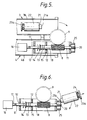
- a tinge assembly according to the second embodiment of the invention as illustrated in Figures 5 to 8 of the present application basically is similar to that of the first embodiment of Figures 1 to 4 and like parts have been given like reference numerals and will not be further described in detail.
- the hinge members 3 and 4 have been shown in Figure 5 only and not in Figures 6 to 8.
- Figures 5 to 8 also includes an Acme externally screw threaded nose portion 20 fixed to and projecting from the free end of the drive shaft 11.
- the nose portion 20 may be formed integrally with the drive shaft 11 by machining therefrom.
- the shaft 11 and nose portion 20 are formed they are formed so as to rotate together.
- a complementary Acme internally screw threaded lock nut 21 non-rotatably but axially movably mounted on the inner hinge member 3. The nut 21 is axially movable along its longitudinal axis, which, in the open position of the assembly 1, is coaxial with the longitudinal axis of the drive shaft 11 and Acme nose portion 20.
- the longitudinal axis 11a of the drive shaft 11 preferably is not coaxial with the longitudinal axis of the hinge member 4 but preferably is slightly spaced from the longitudinal axis of the hinge member 4 on the side thereof remote from the pivot pin 10.
- the longitudinal axis of the nut 21 is not coincident with the longitudinal axis of the hinge member 3 but preferably is spaced slightly therefrom on the side thereof remote from the pivot pin 10. This offset location of the axes is to improve the locking and unlocking action of the nut 21.
- the nut 21 is axially movably mounted in one end of a sleeve 22 to which it is connected for axial but not rotative relative movement in any convenient manner.
- the other end of the sleeve 22 is axially slidably mounted on a spigot fixedly attached to the inner hinge member 3.
- a first spring means in the form of a disc spring 24 is provided between a shoulder portion 23a of the spigot 23 and the sleeve end face 22a.
- the disc spring 24 acts as a pre-load compliance spring.
- a second spring means in the form of a light compression spring preferably is provided within the sleeve between the facing end of the nut 21 and an internal shoulder provided on the sleeve at the end 22a thereof. This compression spring acts to bias the nut 21 axially away from the sleeve.
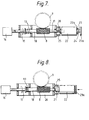
- Deflector means in the form of a collar 25 surrounding the nose portion 20, are provided on the hinge member 4 or on a housing 26 of the worm 8 to contact the leading end 21a of the nut 21, as illustrated in Figure 6, during angular pivoting movement of the inner hinge member 3.
- This contact is such that the collar 25 acts as a cam face which displaces the nut 21 rearwardly against the biasing force of the spring 24 until the nose portion 20 and nut 21 are in axial alignment whereupon the spring 24 re-urges the nut 21 into contact with the nose portion 20 so that on continued rotation of the actuator means drive shaft 11 the screw thread of the nose portion 20 engages the screw thread in the nut 21 drawing the nut 21 onto the nose portion 20.
- the hinge member 3 continues to open as shown in Figure 7 and the nut 21 is further displaced axially into the sleeve 22 against the spring.
- the screw thread on the nose portion 20 starts to engage the internal screw thread on the nut 21 and with the worm wheel 9 at the end of its permitted travel the worm 8 runs along the worm wheel 9 towards the right said side of Figure 8.
- the drive motor 16 continues to run and the worm 8 and nose portion 20 continue to rotate so that the nut 21 is drawn onto the nose portion 20 with the assistance of the compression spring.
- the spigot 23 is pulled axially forward with the nut 21 until the disc spring 23 is clamped tight between the spigot shoulder 23a and the sleeve end face 22a as shown in Figure 8.
- This provides the desired pre-load which can be used to initiate a switch off of the drive motor 16, preferably by means of a microswitch on the spring 23.
- the degree of pre-load can be varied by appropriate choice of the configuration and/or number of elements in the disc spring 23.
- the drive motor 16 could be a stepper motor programmed to rotate the nut 21 by a predetermined number of steps to achieve the correct degree of pre-load on the spring 23.
- Figure 8 represents the hinge assembly 1 in the fully locked open position.
- Reclosure is effected by operating the assembly in the reverse direction.
- Initial rotation of the motor 16 drives the worm 8 along the stationary worm wheel 9 so freeing, i.e. unscrewing, the nose portion 20 from the lock nut 21 and returning the assembly to the Figure 7 position.
- Continued operation of the motor 16 rotates the worm wheel 9 and displaces the hinge member 3 through the Figure 6 position back into the fully closed position of Figure 5.
- Complementary finger and recessed means preferably are provided on the two hinge members 3 and 4 with the finger means projecting substantially parallel to the longitudinal axes of the two hinge members.
- the finger means may be provided on one hinge member and the recess means on the other hinge member or some of the finger means may be provided on one hinge member and some on the other hinge member with the recess means being distributed accordingly on the two hinge members.
- the purpose of the finger and recess means is that the finger means engage in the appropriate complementary recesses in the open position of the hinge assembly 1 to improve the rigidity and transverse load carrying capability of the assembly in the open position.
- the complementary finger and recess means conveniently take the form of a cylindrical, or tapered, finger 27 mounted on the side web 4b of the outer hinge member 4 to project proud of the end thereof towards the inner hinge member 3, and a recessed member 28 having a complementary shaped recess for receiving the leading end of the finger 27.
- the member 28 is mounted on the inner hinge member side web 3b with the mouth of the recess opening towards the outer hinge member 4.
- the actuator locking means includes the drive shaft 11 and drive motor 16 carried in the outer hinge member 4 to extend substantially transversely to the longitudinal axis of the pivot pin 10.
- the worm 8 is fixedly carried on the drive shaft 11 adjacent to the free end thereof which is adjacent to the open pivot pin end of the outer hinge member 4 for rotation with the drive shaft 11.
- the worm wheel is an externally and internally screw threaded worm wheel 29 which together with the worm 8 forms the first of the movable portions.
- the worm wheel 29 is in mesh with the worm 8 and is mounted for rotational, but no substantial axial, movement in the outer hinge member 4 about a rotational axis substantially parallel to that of the drive shaft 11.
- the second movable portion is provided in the form of a flexible rod or strip like screw member 20 made of any convenient material, preferably plastics.
- This member 30 may be of strip like form with the screw thread provided on the two longitudinal edges thereof.
- This member 30 is secured at one end 30a to the pivot pin end of the inner hinge member 3 either fixedly as illustrated in Figures 9 and 10 or pivotally.
- the flexible screw member 30 projects from the inner hinge member 3 towards the pivot pin end of the outer hinge member 4 so that the other end 30b projects into the worm wheel 29 in screw threaded engagement with the internal screw thread thereof.
- a spring loaded support arm 31 is provided which is pivotally mounted at 32 on the outer hinge member 4 to provide support for the flexible screw member 30 such as to prevent it from bending through too similar a radius.
- the worm 8 and worm wheel 29 are each Acme threaded and the drive motor 16 is an electric motor.
Abstract
Description
- This invention relates to a power actuable, openable and closable, lockable and unlockable, hinge assembly having two pivotally interconnected hinge members.
- Hinge assemblies are known having two pivotally interconnected hinge members but such assemblies are conventionally openable by a spring acting between the members to bias them apart into an open position. These conventional assemblies are normally locked in the open position by means of a pin which drops into apertures on the members in the open position. With such known assemblies no provision is made for unlocking or closing the assembly and this presents a serious drawback for some applications such as where it is necessary to open and close a hinge assembly at a position or location remote from the operator.
- For use on a deployable articulated mast or boom a hinge assembly requires to be strong and to afford the possibility of opening and closing by powered actuation so that the mast or boom can be collapsed into individual sections and extended as desired. Such a hinge assembly should be strong enough to withstand side forces on the mast or boom when it is in the deployed extended position and should be capable of being lockable in the open position corresponding to extension of the mast or boom and unlockable when it is desired to close the hinge assembly and thereby collapse the mast or boom.
- According to the present invention there is provided a power actuable, openable and closable, lockable and unlockable, hinge assembly characterised by having pivot means , two hinge members pivotally interconnectable by the pivot means for relative angular movement between an open position in which the hinge members extend substantially co-axially in end-to-end relationship and a closed position in which one hinged member is angularly displaced, with respect to the other hinge member, about the pivot means out of the end-to-end relationship, power drivable actuator locking means having a first movable portion carried on one of the hinge members and a second co-operating movable portion carried on the other of the hinge members and in engagement with said first movable portion, which power drivable actuator locking means is selectively operable to open and lock the hinge members together by pivoting one of the hinge members from the closed position about the pivot means into the substantially co-axial end-to-end relationship of the open position and then causing one of said movable portions to move in one direction relative to the other of said movable portions to lock the hinge members together, and to unlock and close the hinge members by unlocking the end-to-end hinge members by causing one of said movable portions to move in the opposite direction relative to said other movable portion and then to pivot one of the hinge members about the pivot means angularly with respect to the other of the hinge members out of the end-to-end relationship into the closed position.
- Conveniently the pivot means includes a pivot pin and the hinge members are each of substantially elongated channel form and substantially U shaped in cross-section with a base web and two spaced apart side webs, which side webs each have an apertured pivot lug at or near the outermost corner thereof remote from the base web for receiving the pivot pin, and with the hinge members being dimensioned such that the base web of one or inner hinge member is smaller in width than the base web of the other or outer hinge member at the pivot lugs with the pivot pin passing through the aligned lug apertures.
- Preferably the actuator locking means includes a rotatable drive shaft rotatably carried in the outer hinge member to extend substantially transversely to the longitudinal axis of the pivot pin, a screw threaded worm, forming the first of said movable portions, carried on the drive shaft adjacent a free end thereof which is adjacent the open pivot pin end of the outer hinge member, for rotation with the drive shaft, a screw threaded worm wheel, forming the second of said movable portions, in mesh with the worm, which worm wheel is rotationally mounted on the pivot pin and fixed to the inner hinge member for rotation therewith and which worm is mounted for axial slidable movement along said drive shaft against pre-load biasing means, upon continued rotation of the drive shaft with the worm wheel in a stopped position corresponding to the open position of the hinge members, to lock the worm and worm wheel together, rotation of the drive shaft in the other direction initially displacing the worm back along the stationary worm wheel and shaft under the assistance of the pre-load biasing means to unlock the worm wheel and hinge member and then rotating the worm wheel to move the inner hinge member relative to the outer hinge member between the open and closed position.
- Advantageously the assembly includes an Acme externally screw threaded nose portion fixed to and projecting from the free end of the actuator means drive shaft for rotation therewith and a complementary Acme internally screw threaded lock nut non-rotatably but axially movably mounted on the inner hinge member.
- Conveniently the lock nut is axially movably mounted in one end of a sleeve to which it is connected for axial but not rotative relative movement, with the other end of the sleeve being axially slidably mounted on a spigot fixedly attached to the inner hinge member.
- Preferably a first spring means is provided between the spigot and the sleeve resiliently to bias the sleeve axially away from the spigot, and wherein a second spring means is provided between the other end of the sleeve and the end face of the nut innermost in the sleeve to bias the nut axially away from the sleeve, with deflector means being associated with the nose portion on the actuator means drive shaft to contact the leading end of the lock nut during angular pivoting movement of the inner hinge member, displace the nut rearwardly against the biasing force of the second spring means until the nose portion and nut are in axial alignment whereupon the second spring means biasing force re-urges the nut into contact with the nose portion for screw threaded engagement therewith on continued rotation of the actuator means drive shaft.
- Advantageously wherein the actuator locking means includes a rotatable drive shaft rotatably carried in the outer hinge member to extend substantially transversely to the longitudinal axis of the pivot pin, a screw threaded worm fixedly carried on the drive shaft adjacent a free end thereof which is adjacent the open pivot pin end of the outer hinge member for rotation with the drive shaft, an externally and internally screw threaded worm wheel, which together with the worm forms the first of said movable portions, which worm wheel is in mesh with the worm, is mounted for rotational but no substantial axial movement in the outer hinge member about a rotational axis substantially parallel to that of the drive shaft, and a flexible rod or strip-like screw member, forming the second of said movable portions, secured at one end to the pivot pin end of the inner hinge member to project therefrom towards the pivot pin end of the outer hinge member so that the other end of the screw member projects into the worm wheel in screw threaded engagement with the internal screw thread thereof, the arrangement being such that rotation of the drive shaft, and hence of the worm and worm wheel, in one direction pulls the flexible screw member through the worm wheel into the outer hinge member to pull the inner hinge member into the open position and rotation of the drive shaft, and hence of the worm and worm wheel, in the opposite direction pushes the flexible screw member in a direction away from the worm wheel and outer hinge member to push the inner hinge member into the closed position.
- For a better understanding of the present invention, and to show how the same may be carried into effect, reference will now be made, by way of example, to the accompanying drawings, in which;
- Figure 1 is a diagrammatic side view of a hinge assembly according to a first embodiment of the invention shown in an open position,
- Figure 2 is a plan view from above of the hinge assembly of Figure 1,
- Figure 3 is a partially sectioned side view of the hinge assembly of Figures 1 and 2 shown in a fully closed position,
- Figure 4 is a view similar to that of Figure 3, but showing the hinge assembly in the fully open position,
- Figure 5 is a partially sectioned side view similar to that of Figure 3 showing a hinge assembly according to a second embodiment of the invention in a closed position,
- Figure 6 is a view similar to that of Figure 5 showing the hinge assembly rotated through an angle of 163° with a lock nut on one hinge member of the assembly contacting a housing collar on the other hinge member,
- Figure 7 is a view, similar to that of Figure 6, but showing the hinge assembly after rotation through 180° with the lock nut on one tinge member contacting a nose portion on the other hinge member,
- Figure 8 is a view of the hinge assembly of Figure 7 shown in the fully open position with the lock nut and nose portion fully engaged,
- Figure 9 is a diagrammatic partially sectioned side view from above of a hinge assembly according to a third embodiment of the present invention shown in a fully closed position, and
- Figure 10 is a side view of the hinge assembly of Figure 9 shown in a fully open position.
- A power actuable, openable and closable, lockable and unlockable, hinge assembly as generally indicated at 1 in the accompanying drawings is intended primarily for use to interconnect two sections of a collapsible and extensible boom or mast. However although described in the following in terms of its use with such a boom or mast it is to be understood that the hinge assembly of the invention can be used for any other purposes as desired.
- The hinge assembly 1 according to a first embodiment of the invention as shown in Figures 1 to 4 has pivot means 2 and two hinge members, namely an
inner hinge member 3 and anouter hinge member 4 pivotally interconnected by the pivot means 2 for relative angular movement between an open position as shown in Figures 1, 2 and 4 in which the hingemembers inner hinge member 3 is angularly displaced, with respect to theouter hinge member 4 about the pivot means 2 out of the end-to-end relationship. As shown in Figure 3, the open position is pivoted through 180° from the closed position for the purpose of stowing in side byside relationship sections - The hinge assembly 1 of the present invention also includes a power drivable actuator locking means generally indicated at 7 having a first
movable portion 8 carried on theouter hinge member 4 and a second co-operatingmovable portion 9 carried on theinner hinge member 3. The first and secondmovable portions - The actuator locking means 7 is selectively operable to open and lock the
hinge members inner hinge member 3, from the closed position about the pivot means 2 into the substantially coaxial end-to-end relationship of the open position and then causing one of themovable portions hinge members hinge members movable portions inner hinge member 3, about the pivot means 2 angularly with respect to theouter hinge member 4 out of the end-to-end relationship into the closed portion. - The pivot means 2 includes a
pivot pin 10 supported by bearings which may be plain, ball or pre-loaded angular contact bearings, in theouter hinge member 4. Thehinge members base web 3a and 4a and two spaced apartside webs side webs base web 3a, 4a for receiving thepivot pin 10. Thehinge members inner hinge member 3 is smaller in width than thebase web 4a of theouter hinge member 4 so that theinner hinge member 3 fits within theouter hinge member 4 at the pivot lugs 3c and 4c with thepivot pin 10 passing through the aligned lug apertures. - The
outer hinge member 4 is fixedly attached to thehinge pin 10 to rotate therewith. - The
inner hinge member 3 is rotationally supported by bearings which may be plain, ball or pre-loaded angular contact bearings, on thepivot pin 10 for pivotal rotational movement relative thereto. - As can be seen from Figures 1 to 4 the actuator locking means 7 includes a
rotatable drive shaft 11 rotatably carried atbearings 12 in theouter hinge member 4 to extend substantially transversely to the longitudinal axis of thepivot pin 10. Also forming part of themeans 7 is a screw threaded worm, forming the firstmovable portion 8, carried on thedrive shaft 11 adjacent a free end thereof which is adjacent the open pivot pin end of theouter hinge member 4 for rotation with thedrive shaft 11. Preferably theworm 8 is a single start worm. - Also forming part of the actuator locking means 7 is a screw threaded worm wheel, forming the second
movable portion 9, which may be peripherally interrupted as at 9a. Theworm wheel 9 is in mesh with theworm 8 and is rotationally mounted on thepivot pin 10 via bearings to rotate with theinner hinge member 3. - The
worm 8 is mounted for axial slidable movement along theshaft 11 against pre-load biasing means such ascompression spring 13 mounted on theshaft 11 between acollar 14 fixed to theshaft 11 and ashoulder 15 fixed relative to theouter hinge member 4. - The actuator locking means 7 includes a drive motor connected to the end of the
drive shaft 11 remote from the free end. This drive motor preferably is anelectric motor 16 with gearbox housed in and attached to theouter hinge member 4 which drives theshaft 11 by means of amotor output shaft 17 which is flexibly coupled to the adjacent end of thedrive shaft 11. This form of construction allows for a degree of end float between themotor 16 andshaft 11 if necessary. Although themotor 16 has been shown as integral with thehinge assembly member 4 it is alternatively possible to provide a drive motor externally of the assembly so that a plurality of hinge assemblies can be actuated by means of a single drive motor in communication with the individual drive assemblies in a multi section boom or mast via a control drive cable passing through the sections. - The hinge assembly 1 according to the first embodiment of the invention as illustrated in Figures 1 to 4 operates in the following way. With the hinge assembly in the closed position as shown in Figure 3 rotation of the
drive shaft 11 by the electric motor andgear box 16 transmits rotary motion to theworm 8 which in turn, being in mesh with theworm wheel 9, transmits rotary motion to theworm wheel 9. This causes thehinge member 3 to pivot about thepivot pin 10 into the fully closed end-to-end position of thehinge members worm wheel 9 is possible due to end-to-end contact between the hinge members and continued rotation of thedrive shaft 11 by means of the motor andgear box assembly 16 causes theworm 8 to move axially slidably along thedrive shaft 11 against the pre-load biasing means formed by thespring 13 to the extreme position shown in Figure 4 in which the worm and worm wheel are locked together. Rotation of thedrive shaft 11 in the opposite direction initially displaces theworm 8 back along thestationary worm wheel 9 andshaft 11 under the assistance of thepre-load bias spring 13 to unlock theworm wheel 9 and hingemembers worm 8 into the position shown in Figure 3 and continued rotation of theshaft 11 andworm 8 then rotates theworm wheel 9 to move theinner hinge member 3 relative to theouter hinge member 4 back into the closed position as shown in Figure 3. - In general terms the direction of movement of the
hinge member 3 relative to thehinge member 4 depends on the direction of rotation of theworm 8 and on whether or not the worm thread left or right handed. As shown in the accompanying drawings, particularly in Figures 3 and 4 thereof, theworm 8 is mounted on asleeve 18 which is slidably movable on thedrive shaft 11 under axial restraint of thecompression spring 13. When the hinge assembly is to be moved from the closed position of Figure 3 to the fully open position of Figure 4 if the hinge assembly movement resistance torque is less than the pre-load effect of thespring 13 theworm 8 will not move axially. However if the resistance torque is higher then the hinge members will not be displaced until theworm 8 has been displaced axially towards the right into the position shown in Figure 4 where the pre-load in thespring 13 is equal to the hinge resistance torque. - The locking action of the
worm 8 andworm wheel 9 is as follows. When the hinge assembly 1 is in the fully open position of Figures 1, 2 and 4 the hinge torque resistance is much higher in the opening direction than the pre-load on theworm 8. Thus if theworm 8 is rotated further in the opening direction, it is axially displaced towards the right into the position shown in Figure 4 and the pre-load in thespring 13 is increased. This increase in the spring pre-load causing the hinge assembly itself to be pre-loaded. The hinge pre-load is dependent on the spring pre-load, the size of the worm/worm wheel gear set and the geometry of contact points or stops 19 on thehinge members worm 8 is pre-loaded against itsspring 13 the pre-load in the hinge assembly 1 is maintained after the drive torque is removed from theworm 8. Thus controllable compliance is built into the worm/worm wheel gear set so that a controllable and predictable pre-load is achievable simply by tightening up the gear set. A separate pre-loading or locking mechanism is thus not necessary. The compliance within the gear set makes the hinge assembly 1 partially back drivable which is an advantage during vibration or loading. Additionally the hinge assembly 1 according to the embodiment of Figures 1 to 4 can be pre-loaded in the open condition or the closed condition. - Preferably the
worm 8 andworm wheel 9 are each Acme threaded. - A tinge assembly according to the second embodiment of the invention as illustrated in Figures 5 to 8 of the present application basically is similar to that of the first embodiment of Figures 1 to 4 and like parts have been given like reference numerals and will not be further described in detail. For the sake of convenience the
hinge members - However the embodiment of Figures 5 to 8 also includes an Acme externally screw threaded
nose portion 20 fixed to and projecting from the free end of thedrive shaft 11. Conveniently thenose portion 20 may be formed integrally with thedrive shaft 11 by machining therefrom. However theshaft 11 andnose portion 20 are formed they are formed so as to rotate together. Also provided is a complementary Acme internally screw threadedlock nut 21 non-rotatably but axially movably mounted on theinner hinge member 3. Thenut 21 is axially movable along its longitudinal axis, which, in the open position of the assembly 1, is coaxial with the longitudinal axis of thedrive shaft 11 andAcme nose portion 20. As can be seen from the drawings, particularly from Figure 1 thereof, thelongitudinal axis 11a of thedrive shaft 11 preferably is not coaxial with the longitudinal axis of thehinge member 4 but preferably is slightly spaced from the longitudinal axis of thehinge member 4 on the side thereof remote from thepivot pin 10. Similarly the longitudinal axis of thenut 21 is not coincident with the longitudinal axis of thehinge member 3 but preferably is spaced slightly therefrom on the side thereof remote from thepivot pin 10. This offset location of the axes is to improve the locking and unlocking action of thenut 21. - The
nut 21 is axially movably mounted in one end of asleeve 22 to which it is connected for axial but not rotative relative movement in any convenient manner. The other end of thesleeve 22 is axially slidably mounted on a spigot fixedly attached to theinner hinge member 3. - As can be seen from Figure 7 in particular a first spring means in the form of a
disc spring 24 is provided between ashoulder portion 23a of thespigot 23 and thesleeve end face 22a. Thedisc spring 24 acts as a pre-load compliance spring. A second spring means in the form of a light compression spring preferably is provided within the sleeve between the facing end of thenut 21 and an internal shoulder provided on the sleeve at theend 22a thereof. This compression spring acts to bias thenut 21 axially away from the sleeve. - Deflector means, in the form of a
collar 25 surrounding thenose portion 20, are provided on thehinge member 4 or on ahousing 26 of theworm 8 to contact theleading end 21a of thenut 21, as illustrated in Figure 6, during angular pivoting movement of theinner hinge member 3. This contact is such that thecollar 25 acts as a cam face which displaces thenut 21 rearwardly against the biasing force of thespring 24 until thenose portion 20 andnut 21 are in axial alignment whereupon thespring 24 re-urges thenut 21 into contact with thenose portion 20 so that on continued rotation of the actuator meansdrive shaft 11 the screw thread of thenose portion 20 engages the screw thread in thenut 21 drawing thenut 21 onto thenose portion 20. - The operation of a hinge assembly 1 according to the second embodiment will now be described with reference to Figures 5 to 8 of the accompanying drawings. With the two
hinge members drive motor 16 rotates theworm wheel 9 through 163° via theworm 8, so that thehinge member 3 moves into the position shown in Figure 6. After rotation of about 163° the leading end of 21a of thenut 21 contacts thecollar 25 as shown in Figure 6 and thenut 21 begins to move axially rearwardly towards thespigot shoulder 23a against the action of the return spring withdisc spring 24 being lightly compressed between thesleeve 22 andspigot shoulder 23a. - The
hinge member 3 continues to open as shown in Figure 7 and thenut 21 is further displaced axially into thesleeve 22 against the spring. At full rotation through 180° as shown in Figure 8 the screw thread on thenose portion 20 starts to engage the internal screw thread on thenut 21 and with theworm wheel 9 at the end of its permitted travel theworm 8 runs along theworm wheel 9 towards the right said side of Figure 8. - The
drive motor 16 continues to run and theworm 8 andnose portion 20 continue to rotate so that thenut 21 is drawn onto thenose portion 20 with the assistance of the compression spring. By virtue of the attachment of thenut 21 to thespigot 23, thespigot 23 is pulled axially forward with thenut 21 until thedisc spring 23 is clamped tight between thespigot shoulder 23a and thesleeve end face 22a as shown in Figure 8. This provides the desired pre-load which can be used to initiate a switch off of thedrive motor 16, preferably by means of a microswitch on thespring 23. The degree of pre-load can be varied by appropriate choice of the configuration and/or number of elements in thedisc spring 23. Alternatively, and not shown, thedrive motor 16 could be a stepper motor programmed to rotate thenut 21 by a predetermined number of steps to achieve the correct degree of pre-load on thespring 23. Thus Figure 8 represents the hinge assembly 1 in the fully locked open position. - Reclosure is effected by operating the assembly in the reverse direction. Initial rotation of the
motor 16 drives theworm 8 along thestationary worm wheel 9 so freeing, i.e. unscrewing, thenose portion 20 from thelock nut 21 and returning the assembly to the Figure 7 position. Continued operation of themotor 16 rotates theworm wheel 9 and displaces thehinge member 3 through the Figure 6 position back into the fully closed position of Figure 5. - Complementary finger and recessed means preferably are provided on the two
hinge members - As shown in Figure 1 the complementary finger and recess means conveniently take the form of a cylindrical, or tapered,
finger 27 mounted on theside web 4b of theouter hinge member 4 to project proud of the end thereof towards theinner hinge member 3, and a recessedmember 28 having a complementary shaped recess for receiving the leading end of thefinger 27. Themember 28 is mounted on the inner hingemember side web 3b with the mouth of the recess opening towards theouter hinge member 4. - The third embodiment of the hinge assembly according to the present invention is shown in Figures 9 and 10 in which the actuator locking means includes the
drive shaft 11 and drivemotor 16 carried in theouter hinge member 4 to extend substantially transversely to the longitudinal axis of thepivot pin 10. Theworm 8 is fixedly carried on thedrive shaft 11 adjacent to the free end thereof which is adjacent to the open pivot pin end of theouter hinge member 4 for rotation with thedrive shaft 11. However in this embodiment the worm wheel is an externally and internally screw threadedworm wheel 29 which together with theworm 8 forms the first of the movable portions. Theworm wheel 29 is in mesh with theworm 8 and is mounted for rotational, but no substantial axial, movement in theouter hinge member 4 about a rotational axis substantially parallel to that of thedrive shaft 11. - The second movable portion is provided in the form of a flexible rod or strip like
screw member 20 made of any convenient material, preferably plastics. Thismember 30 may be of strip like form with the screw thread provided on the two longitudinal edges thereof. Thismember 30 is secured at oneend 30a to the pivot pin end of theinner hinge member 3 either fixedly as illustrated in Figures 9 and 10 or pivotally. Theflexible screw member 30 projects from theinner hinge member 3 towards the pivot pin end of theouter hinge member 4 so that theother end 30b projects into theworm wheel 29 in screw threaded engagement with the internal screw thread thereof. A spring loadedsupport arm 31 is provided which is pivotally mounted at 32 on theouter hinge member 4 to provide support for theflexible screw member 30 such as to prevent it from bending through too similar a radius. - Thus with the hinge assembly in the fully closed position as shown in Figure 9 rotation of the
drive shaft 11 and hence of theworm 8 andworm wheel 29 in one direction pulls theflexible screw member 30 through theworm wheel 29 into theouter hinge member 4 to pull theinner hinge member 3 into the open position as shown in Figure 10 where it is held in position by the pre-load beween themotor 16,worm 8,worm wheel 29 and screw thread on thescrew member 30. In the fully open position of Figure 10 theflexible screw member 30 has moved into a substantially linear condition from the substantially arcuate condition shown in Figure 9. In the position of Figure 10 the spring loadedsupport arm 31 has folded back so that it lies within theinner hinge member 3. Rotation of thedrive shaft 11, and hence of theworm 8 andworm wheel 29 in the opposite direction pushes theflexible screw member 30 in a direction away from theworm wheel 29 andouter hinge member 4 to push the inner hinge member back into the closed position as shown in Figure 9. Preferably theworm 8 andworm wheel 29 are each Acme threaded and thedrive motor 16 is an electric motor.
Claims (17)
- A power actuable openable and closable, lockable and unlockable, hinge assembly, characterised by having pivot means (2), two hinge members (3, 4) pivotally interconnectable by the pivot means (2) for relative angular movement between an open position in which the hinge members (3, 4) extend substantially co-axially in end-to-end relationship and a closed position in which one hinged member (3) is angularly displaced, with respect to the other hinge member (4), about the pivot means (2) out of the end-to-end relationship, power drivable actuator locking means (7) having a first movable portion (8, 29) carried on one of the hinge members (4) and a second co-operating movable portion (9, 30) carried on the other of the hinge members (3) and in engagement with said first movable portion (8, 29) which power drivable actuator locking means (7) is selectively operable to open and lock the hinge members (3, 4) together by pivoting one of the hinge members (3) from the closed position about the pivot means (2) into the substantially co-axial end-to-end relationship of the open position and then causing one of said movable portions (8, 29, 9, 30) to move in one direction relative to the other of said movable portions to lock the hinge members (3, 4) together, and to unlock and close the hinge members (3, 4) by unlocking the end-to-end hinge members (3, 4) by causing one of said movable portions (8, 29, 9, 30) to move in the opposite direction relative to said other movable portion and then to pivot one of the hinge members (3) about the pivot means (2) angularly with respect to the other of the hinge members (4) out of the end-to-end relationship into the closed position.
- An assembly according to claim 1 wherein, the pivot means (2) includes a pivot pin (10) and wherein the hinge members (3, 4) are each of substantially elongated channel form and substantially U shaped in cross-section with a base web (3a, 4a) and two spaced apart side webs (3b, 4b), which side webs (3b, 4b) each have an apertured pivot lug (3c, 4c) at or near the outermost corner thereof remote from the base web (3a, 4a) for receiving the pivot pin (10), and with the hinge members (3, 4) being dimensioned such that the base web (3a) of one or the inner hinge member (3) is smaller in width than the base web (4a) of the other or outer hinge member (4) so that the inner hinge member (3) fits within the outer hinge member (4) at the pivot lugs (3c, 4c) with the pivot pin (10) passing through the aligned lug apertures.
- An assembly according to claim 2, wherein the outer hinge member (4) is fixedly attached to the hinge pin (10) to rotate therewith.
- An assembly according to claim 2 or claim 3, wherein the inner hinge member (3) is rotationally supported by bearings on the pivot pin (10) for pivotal rotational movement relative thereto.
- An assembly according to any one of claims 2 to 4, wherein the actuator locking means (7) includes a rotatable drive shaft (11) rotatably serried in the outer hinge member (4) to extend substantially transversely to the longitudinal axis of the pivot pin (10), a screw threaded worm, forming the first (8) of said movable portions, carried on the drive shaft (11) adjacent a free end thereof which is adjacent the open pivot pin end of the outer hinge member (4), for rotation with the drive shaft (11), a screw threaded worm wheel, forming the second (9) of said movable portions, in mesh with the worm, which worm wheel (9) is rotationally mounted on the pivot pin (10) and fixed to the inner hinge member (3) for rotation therewith, and which worm (8) is mounted for axial slidable movement along said drive shaft (11) against pre-load biasing means (13), upon continued rotation of the drive shaft (11) with the worm wheel (9) in a stopped position corresponding to the open position of the hinge members (3, 4), to lock the worm (8) and worm wheel (9) together, and thereby the open position, end-to-end hinge members (3, 4) together, rotation of the drive shaft (11) in the other direction initially displacing the worm (8) back along the stationary worm wheel (9) and shaft (11) under the assistance of the pre-load biasing means (13) to unlock the worm wheel (9) and hinge members (3, 4) and then rotating the worm wheel (9) to move the inner hinge member (3) relative to the outer hinge member (4) between the open and closed position.
- An assembly according to claim 5, wherein the pre-load biasing means is a compression spring (13) mounted on the drive shaft (11) between a collar (14) fixed to the shaft (11) and a shoulder (15) fixed relative to the outer hinge member (4).
- An assembly according to claim 5 or claim 6, wherein the worm (8) and worm wheel (9) are each Acme threaded.
- An assembly according to any one of claims 5 to 7, wherein the actuator means (7) includes a drive motor connected to the end of the drive shaft (11) remote from the free end.
- An assembly according to claim 8, wherein the drive motor is an electric motor (16) housed in and attached to the outer hinge member (4).
- An assembly according to any one of claims 5 to 9, including an Acme externally screw threaded nose portion (20) fixed to and projecting from the free end of the actuator means drive shaft (11) for rotation therewith and a complementary Acme internally screw threaded lock nut (21) non-rotatably but axially movably mounted on the inner hinge member (3).
- An assembly according to claim 10, wherein the lock nut (21) is axially movable along its longitudinal axis, which, in the open position of the assembly (1), is coaxial with the longitudinal axis of the drive shaft (11) and Acme nose portion (20).
- An assembly according to claim 11, wherein the lock nut (21) is axially movably mounted in one end of a sleeve (22) to which it is connected for axial but not rotative relative movement with the other end of the sleeve (22) being axially slidably mounted on a spigot fixedly attached to like inner hinge member (3).
- An assembly according to claim 12, wherein a first spring means (24) is provided between the spigot (23) and the sleeve (22) resiliently to bias the sleeve (22) axially away from the spigot (23), and wherein a second spring means is provided between the other end of the sleeve (22) and the end face of the nut (21) innermost in the sleeve (22) to bias the nut (21) axially away from the sleeve (22) with deflector means (25) being associated with the nose portion (20) on the actuator means drive shaft (11) to contact the leading end (21a) of the lock nut (21) during angular pivoting movement of the inner hinge member (3), displace the nut (21) rearwardly against the biasing force of the second spring means until the nose potion (20) and nut (21) are in axial alignment whereupon the second spring means biasing force re-urges the nut (21) into contact with the nose portion (20) for screw threaded engagement therewith on continued rotation of the actuator means drive shaft (11).
- An assembly according to any one of claims 2 to 4, wherein the actuator locking means (7) includes a rotatable drive shaft (11) rotatably carried in the outer hinge member (4) to extend substantially transversely to the longitudinal axis of the pivot pin (10), a screw threaded worm (8) fixedly carried on the drive shaft (11) adjacent a free end thereof which is adjacent the open pivot pin end of the outer hinge member (4) for rotation with the drive shaft (11), an externally and internally screw threaded worm wheel (29), which together with the worm (8) forms the first of said movable potions, which worm wheel (29) is in mesh with the worm (8), is mounted for rotational but no substantial movement in the outer hinge member (4) about a rotational axis substantially parallel to that of the drive shaft (11), and a flexible rod or strip-like screw member (30), forming the second of said movable portions, secured at one end (30a) to the pivot pin end of the inner hinge member (3) to project therefrom towards the pivot pin end of the outer hinge member so that the other end (30b) of the screw member (30) projects into the worm wheel (29) in screw threaded engagement with the internal screw thread thereof, the arrangement being such that rotation of the drive shaft, and hence of the worm (8) and worm wheel (29), in one direction pulls the flexible screw member (30) through the worm wheel (29) into the outer hinge member (4) to pull the inner hinge member (3) into the open position and rotation of the drive shaft (11), and hence of the worm (8) and worm wheel (29), in the opposite direction pushes the flexible screw member (30) in a direction away from the worm wheel (29) and outer hinge member (4) to push the inner hinge member (3) into the closed position.
- An assembly according to claim 14, wherein the worm (8) and worm wheel (29) are each Acme threaded and the drive motor (16) is an electric motor housed in and attached to the outer hinge member (4).
- An assembly according to any one of claims 1 to 15, including complementary finger and recess means (27, 28) provided on the two hinge members (3, 4) for engagement in the open position of the assembly (1) for improving the rigidity and transverse load carrying capability of the assembly (1) in the open position.
- A collapsible boom or mast having a plurality of elongated sections (5, 6) and at least one hinge assembly (1) according to any one of claim 1 to 16, with the or each assembly (1) interconnecting two adjoining sections (5, 6).
Applications Claiming Priority (2)
| Application Number | Priority Date | Filing Date | Title |
|---|---|---|---|
| GB9105917A GB9105917D0 (en) | 1991-03-20 | 1991-03-20 | A power actuable,openable and closable lockable and unlockable,hinge assembly |
| GB9105917 | 1991-03-20 |
Publications (2)
| Publication Number | Publication Date |
|---|---|
| EP0505134A1 true EP0505134A1 (en) | 1992-09-23 |
| EP0505134B1 EP0505134B1 (en) | 1997-01-15 |
Family
ID=10691898
Family Applications (1)
| Application Number | Title | Priority Date | Filing Date |
|---|---|---|---|
| EP19920302263 Expired - Lifetime EP0505134B1 (en) | 1991-03-20 | 1992-03-16 | A power actuable, openable and closeable, lockable and unlockable, hinge assembly |
Country Status (4)
| Country | Link |
|---|---|
| EP (1) | EP0505134B1 (en) |
| DE (1) | DE69216668D1 (en) |
| ES (1) | ES2097278T3 (en) |
| GB (1) | GB9105917D0 (en) |
Cited By (4)
| Publication number | Priority date | Publication date | Assignee | Title |
|---|---|---|---|---|
| GB2343483A (en) * | 1998-11-09 | 2000-05-10 | Moog Inc | Driven hinge with automatic driver-operated lock. |
| EP1298274A1 (en) * | 2001-09-29 | 2003-04-02 | Landert-Motoren-AG | Doorwing drive system with spring closing means |
| NL1031542C2 (en) * | 2006-04-07 | 2007-10-09 | Stenman Holland Nv | Assembly of a panel and a frame, in particular a pivotable skylight window and a respective frame of a building. |
| WO2023109420A1 (en) * | 2021-12-13 | 2023-06-22 | 舒继锋 | Electric control rotating arm locking device and automatic folding vehicle |
Citations (7)
| Publication number | Priority date | Publication date | Assignee | Title |
|---|---|---|---|---|
| DE653755C (en) * | 1936-04-13 | 1937-12-02 | Ternstedt Mfg Company | Window adjustment device equipped with a lock |
| US3295699A (en) * | 1964-08-28 | 1967-01-03 | Jr John P Bauernschub | Folding boom assembly |
| US3296757A (en) * | 1965-06-23 | 1967-01-10 | Louis N Goodman | Equipment mast arrangement |
| EP0169296A1 (en) * | 1984-02-07 | 1986-01-29 | Yvan Poulin | Drive mechanism |
| DE3731931A1 (en) * | 1987-09-23 | 1989-04-06 | Pfleiderer Fa G A | MAST FOR MEASURING OR LIGHTING PURPOSES, ESPECIALLY FOR FLYING FIRE |
| AU603797B2 (en) * | 1986-05-23 | 1990-11-29 | Industrial Galvanisers Corporation Pty Ltd | A pole construction |
| EP0430410A1 (en) * | 1989-11-23 | 1991-06-05 | British Aerospace Public Limited Company | A power actuable, openable and closable, lockable and unlockable, hinge assembly |
-
1991
- 1991-03-20 GB GB9105917A patent/GB9105917D0/en active Pending
-
1992
- 1992-03-16 DE DE69216668T patent/DE69216668D1/en not_active Expired - Lifetime
- 1992-03-16 ES ES92302263T patent/ES2097278T3/en not_active Expired - Lifetime
- 1992-03-16 EP EP19920302263 patent/EP0505134B1/en not_active Expired - Lifetime
Patent Citations (7)
| Publication number | Priority date | Publication date | Assignee | Title |
|---|---|---|---|---|
| DE653755C (en) * | 1936-04-13 | 1937-12-02 | Ternstedt Mfg Company | Window adjustment device equipped with a lock |
| US3295699A (en) * | 1964-08-28 | 1967-01-03 | Jr John P Bauernschub | Folding boom assembly |
| US3296757A (en) * | 1965-06-23 | 1967-01-10 | Louis N Goodman | Equipment mast arrangement |
| EP0169296A1 (en) * | 1984-02-07 | 1986-01-29 | Yvan Poulin | Drive mechanism |
| AU603797B2 (en) * | 1986-05-23 | 1990-11-29 | Industrial Galvanisers Corporation Pty Ltd | A pole construction |
| DE3731931A1 (en) * | 1987-09-23 | 1989-04-06 | Pfleiderer Fa G A | MAST FOR MEASURING OR LIGHTING PURPOSES, ESPECIALLY FOR FLYING FIRE |
| EP0430410A1 (en) * | 1989-11-23 | 1991-06-05 | British Aerospace Public Limited Company | A power actuable, openable and closable, lockable and unlockable, hinge assembly |
Cited By (5)
| Publication number | Priority date | Publication date | Assignee | Title |
|---|---|---|---|---|
| GB2343483A (en) * | 1998-11-09 | 2000-05-10 | Moog Inc | Driven hinge with automatic driver-operated lock. |
| GB2343483B (en) * | 1998-11-09 | 2002-09-18 | Moog Inc | Driven hinge with automatic driver-operated lock |
| EP1298274A1 (en) * | 2001-09-29 | 2003-04-02 | Landert-Motoren-AG | Doorwing drive system with spring closing means |
| NL1031542C2 (en) * | 2006-04-07 | 2007-10-09 | Stenman Holland Nv | Assembly of a panel and a frame, in particular a pivotable skylight window and a respective frame of a building. |
| WO2023109420A1 (en) * | 2021-12-13 | 2023-06-22 | 舒继锋 | Electric control rotating arm locking device and automatic folding vehicle |
Also Published As
| Publication number | Publication date |
|---|---|
| ES2097278T3 (en) | 1997-04-01 |
| GB9105917D0 (en) | 1991-05-08 |
| EP0505134B1 (en) | 1997-01-15 |
| DE69216668D1 (en) | 1997-02-27 |
Similar Documents
| Publication | Publication Date | Title |
|---|---|---|
| US11578513B2 (en) | Handle device for a motor vehicle door | |
| US5588258A (en) | Power operator for pivotable vehicle closure element | |
| US5438176A (en) | Three-position switch actuating mechanism | |
| US5957237A (en) | Motorized collapsible step | |
| US6685239B2 (en) | Vehicle door opening closing device | |
| US5310138A (en) | Wing fold actuator system for aircraft | |
| US5280258A (en) | Spring-powered operator for a power circuit breaker | |
| US7980624B2 (en) | Device for actuating the pivoting movement of a vehicle flap | |
| KR970004303B1 (en) | Apparatus for disconnecting a switch of a high voltage electric circuit | |
| US4586329A (en) | Anti rotation device | |
| EP0685662A2 (en) | A linear actuator | |
| US20050155289A1 (en) | Power lift gate actuator | |
| US4902067A (en) | Air spoiler retracting device | |
| US4373690A (en) | Deployable support structure for spacecrafts | |
| US20180001997A1 (en) | Aircraft undercarriage with a rotary drive actuator | |
| US4575025A (en) | Fin deployment mechanism for missiles | |
| US4597129A (en) | Windscreen wiper device | |
| EP0505134A1 (en) | A power actuable, openable and closeable, lockable and unlockable, hinge assembly | |
| US4188631A (en) | Linkage apparatus for synchronizing aircraft door movements with the deployment of a door-enclosed antenna | |
| US7997539B2 (en) | Device and method for twisting and clamping moveable flaps | |
| EP0430410B1 (en) | A power actuable, openable and closable, lockable and unlockable, hinge assembly | |
| CA3005833A1 (en) | Grain bin cover opening system | |
| US20050236597A1 (en) | Actuator for reversibly displacing a valve flap of a valve | |
| GB2191681A (en) | Windscreen wiper drive transmission mechanism | |
| US6013886A (en) | High-speed control device for a high voltage connection apparatus, in particular a grounding disconnector |
Legal Events
| Date | Code | Title | Description |
|---|---|---|---|
| PUAI | Public reference made under article 153(3) epc to a published international application that has entered the european phase |
Free format text: ORIGINAL CODE: 0009012 |
|
| 17P | Request for examination filed |
Effective date: 19920328 |
|
| AK | Designated contracting states |
Kind code of ref document: A1 Designated state(s): BE CH DE ES FR GB IT LI NL |
|
| RAP3 | Party data changed (applicant data changed or rights of an application transferred) |
Owner name: BRITISH AEROSPACE PUBLIC LIMITED COMPANY |
|
| 17Q | First examination report despatched |
Effective date: 19940318 |
|
| RAP1 | Party data changed (applicant data changed or rights of an application transferred) |
Owner name: MATRA MARCONI SPACE UK LIMITED |
|
| GRAG | Despatch of communication of intention to grant |
Free format text: ORIGINAL CODE: EPIDOS AGRA |
|
| GRAG | Despatch of communication of intention to grant |
Free format text: ORIGINAL CODE: EPIDOS AGRA |
|
| GRAH | Despatch of communication of intention to grant a patent |
Free format text: ORIGINAL CODE: EPIDOS IGRA |
|
| GRAH | Despatch of communication of intention to grant a patent |
Free format text: ORIGINAL CODE: EPIDOS IGRA |
|
| GRAA | (expected) grant |
Free format text: ORIGINAL CODE: 0009210 |
|
| AK | Designated contracting states |
Kind code of ref document: B1 Designated state(s): BE CH DE ES FR GB IT LI NL |
|
| PG25 | Lapsed in a contracting state [announced via postgrant information from national office to epo] |
Ref country code: BE Effective date: 19970115 Ref country code: FR Effective date: 19970115 Ref country code: IT Free format text: LAPSE BECAUSE OF FAILURE TO SUBMIT A TRANSLATION OF THE DESCRIPTION OR TO PAY THE FEE WITHIN THE PRE;WARNING: LAPSES OF ITALIAN PATENTS WITH EFFECTIVE DATE BEFORE 2007 MAY HAVE OCCURRED AT ANY TIME BEFORE 2007. THE CORRECT EFFECTIVE DATE MAY BE DIFFERENT FROM THE ONE RECORDED.SCRIBED TIME-LIMIT Effective date: 19970115 |
|
| REG | Reference to a national code |
Ref country code: CH Ref legal event code: EP Ref country code: CH Ref legal event code: NV Representative=s name: JOHN P. MUNZINGER INGENIEUR-CONSEIL |
|
| REF | Corresponds to: |
Ref document number: 69216668 Country of ref document: DE Date of ref document: 19970227 |
|
| REG | Reference to a national code |
Ref country code: ES Ref legal event code: FG2A Ref document number: 2097278 Country of ref document: ES Kind code of ref document: T3 |
|
| PG25 | Lapsed in a contracting state [announced via postgrant information from national office to epo] |
Ref country code: DE Effective date: 19970416 |
|
| EN | Fr: translation not filed | ||
| PLBE | No opposition filed within time limit |
Free format text: ORIGINAL CODE: 0009261 |
|
| STAA | Information on the status of an ep patent application or granted ep patent |
Free format text: STATUS: NO OPPOSITION FILED WITHIN TIME LIMIT |
|
| 26N | No opposition filed | ||
| REG | Reference to a national code |
Ref country code: GB Ref legal event code: IF02 |
|
| REG | Reference to a national code |
Ref country code: CH Ref legal event code: NV Representative=s name: CRONIN INTELLECTUAL PROPERTY Ref country code: CH Ref legal event code: PUE Owner name: EADS ASTRIUM LIMITED Free format text: MATRA MARCONI SPACE UK LIMITED#THE GROVE WARREN LANE#STANMORE MIDDLESEX HA7 4LY (GB) -TRANSFER TO- EADS ASTRIUM LIMITED#GUNNELS WOOD ROAD#STEVENAGE, HERTFORDSHIRE (GB) |
|
| REG | Reference to a national code |
Ref country code: GB Ref legal event code: 732E |
|
| NLS | Nl: assignments of ep-patents |
Owner name: EADS ASTRIUM LIMITED Effective date: 20060228 |
|
| NLT1 | Nl: modifications of names registered in virtue of documents presented to the patent office pursuant to art. 16 a, paragraph 1 |
Owner name: MMS SPACE UK LIMITED |
|
| REG | Reference to a national code |
Ref country code: CH Ref legal event code: PCAR Free format text: CRONIN INTELLECTUAL PROPERTY;CHEMIN DE PRECOSSY 31;1260 NYON (CH) |
|
| REG | Reference to a national code |
Ref country code: CH Ref legal event code: PFA Owner name: ASTRIUM LIMITED Free format text: EADS ASTRIUM LIMITED#GUNNELS WOOD ROAD#STEVENAGE, HERTFORDSHIRE (GB) -TRANSFER TO- ASTRIUM LIMITED#GUNNELS WOOD ROAD#STEVENAGE, HERTFORDSHIRE SG1 2AS (GB) |
|
| PGFP | Annual fee paid to national office [announced via postgrant information from national office to epo] |
Ref country code: ES Payment date: 20100326 Year of fee payment: 19 Ref country code: CH Payment date: 20100325 Year of fee payment: 19 |
|
| PGFP | Annual fee paid to national office [announced via postgrant information from national office to epo] |
Ref country code: GB Payment date: 20100322 Year of fee payment: 19 |
|
| PGFP | Annual fee paid to national office [announced via postgrant information from national office to epo] |
Ref country code: NL Payment date: 20100315 Year of fee payment: 19 |
|
| REG | Reference to a national code |
Ref country code: NL Ref legal event code: V1 Effective date: 20111001 |
|
| REG | Reference to a national code |
Ref country code: CH Ref legal event code: PL |
|
| GBPC | Gb: european patent ceased through non-payment of renewal fee |
Effective date: 20110316 |
|
| PG25 | Lapsed in a contracting state [announced via postgrant information from national office to epo] |
Ref country code: LI Free format text: LAPSE BECAUSE OF NON-PAYMENT OF DUE FEES Effective date: 20110331 Ref country code: NL Free format text: LAPSE BECAUSE OF NON-PAYMENT OF DUE FEES Effective date: 20111001 Ref country code: CH Free format text: LAPSE BECAUSE OF NON-PAYMENT OF DUE FEES Effective date: 20110331 |
|
| PG25 | Lapsed in a contracting state [announced via postgrant information from national office to epo] |
Ref country code: GB Free format text: LAPSE BECAUSE OF NON-PAYMENT OF DUE FEES Effective date: 20110316 |
|
| REG | Reference to a national code |
Ref country code: ES Ref legal event code: FD2A Effective date: 20120424 |
|
| PG25 | Lapsed in a contracting state [announced via postgrant information from national office to epo] |
Ref country code: ES Free format text: LAPSE BECAUSE OF NON-PAYMENT OF DUE FEES Effective date: 20110317 |