EP0504991B1 - Teilnehmersteuergerät mit gemeinsamen Störungsmodulen für Kabelfernsehen - Google Patents
Teilnehmersteuergerät mit gemeinsamen Störungsmodulen für Kabelfernsehen Download PDFInfo
- Publication number
- EP0504991B1 EP0504991B1 EP92200717A EP92200717A EP0504991B1 EP 0504991 B1 EP0504991 B1 EP 0504991B1 EP 92200717 A EP92200717 A EP 92200717A EP 92200717 A EP92200717 A EP 92200717A EP 0504991 B1 EP0504991 B1 EP 0504991B1
- Authority
- EP
- European Patent Office
- Prior art keywords
- frequency
- subscriber
- control
- oscillators
- signals
- Prior art date
- Legal status (The legal status is an assumption and is not a legal conclusion. Google has not performed a legal analysis and makes no representation as to the accuracy of the status listed.)
- Expired - Lifetime
Links
- 230000002452 interceptive effect Effects 0.000 claims description 4
- 238000010586 diagram Methods 0.000 description 4
- 239000002131 composite material Substances 0.000 description 3
- 238000000034 method Methods 0.000 description 2
- 238000013475 authorization Methods 0.000 description 1
- 239000003990 capacitor Substances 0.000 description 1
- 230000003247 decreasing effect Effects 0.000 description 1
- 238000001914 filtration Methods 0.000 description 1
- 238000002955 isolation Methods 0.000 description 1
- 239000000463 material Substances 0.000 description 1
- 239000011159 matrix material Substances 0.000 description 1
Images
Classifications
-
- H—ELECTRICITY
- H04—ELECTRIC COMMUNICATION TECHNIQUE
- H04K—SECRET COMMUNICATION; JAMMING OF COMMUNICATION
- H04K3/00—Jamming of communication; Counter-measures
- H04K3/80—Jamming or countermeasure characterized by its function
- H04K3/82—Jamming or countermeasure characterized by its function related to preventing surveillance, interception or detection
- H04K3/825—Jamming or countermeasure characterized by its function related to preventing surveillance, interception or detection by jamming
-
- H—ELECTRICITY
- H04—ELECTRIC COMMUNICATION TECHNIQUE
- H04K—SECRET COMMUNICATION; JAMMING OF COMMUNICATION
- H04K3/00—Jamming of communication; Counter-measures
- H04K3/40—Jamming having variable characteristics
- H04K3/41—Jamming having variable characteristics characterized by the control of the jamming activation or deactivation time
-
- H—ELECTRICITY
- H04—ELECTRIC COMMUNICATION TECHNIQUE
- H04K—SECRET COMMUNICATION; JAMMING OF COMMUNICATION
- H04K3/00—Jamming of communication; Counter-measures
- H04K3/40—Jamming having variable characteristics
- H04K3/42—Jamming having variable characteristics characterized by the control of the jamming frequency or wavelength
-
- H—ELECTRICITY
- H04—ELECTRIC COMMUNICATION TECHNIQUE
- H04N—PICTORIAL COMMUNICATION, e.g. TELEVISION
- H04N7/00—Television systems
- H04N7/16—Analogue secrecy systems; Analogue subscription systems
- H04N7/166—Passage/non-passage of the television signal, e.g. jamming, band suppression
-
- H—ELECTRICITY
- H04—ELECTRIC COMMUNICATION TECHNIQUE
- H04K—SECRET COMMUNICATION; JAMMING OF COMMUNICATION
- H04K2203/00—Jamming of communication; Countermeasures
- H04K2203/10—Jamming or countermeasure used for a particular application
- H04K2203/14—Jamming or countermeasure used for a particular application for the transfer of light or images, e.g. for video-surveillance, for television or from a computer screen
-
- H—ELECTRICITY
- H04—ELECTRIC COMMUNICATION TECHNIQUE
- H04K—SECRET COMMUNICATION; JAMMING OF COMMUNICATION
- H04K3/00—Jamming of communication; Counter-measures
- H04K3/40—Jamming having variable characteristics
- H04K3/43—Jamming having variable characteristics characterized by the control of the jamming power, signal-to-noise ratio or geographic coverage area
Definitions
- CATV cable television
- Such control devices allow all programming channels available to a cable subscriber to be selected by the subscriber's receiver or VCR, but these devices also incorporate means to selectively interdict or "jam" certain signals on those channels on a per subscriber basis in order to provide for pay television or subscription television services.
- EP-A-265,349 describes a multichannel signal distribution control system in which a band-limited noise source and a signal translator provide a noise signal in a frequency band corresponding to that of a channel to be selectively disabled.
- the noise signal is added to the signals for specific subscriber output parts, through a switching arrangement, in order to obscure the signal on the selected channel of that subscriber.
- WO-A-89/08966 describes an off premises cable television interdiction apparatus which comprises a microprocessor actuation and control means for actuating and controlling a plurality of frequency agile voltage controlled oscillators.
- the voltage controlled oscillators selectively jam only unauthorized premium programming transmitted in the clear from a head end to a particular subscriber.
- One object of the invention is to provide a subscriber control device which provides substantial control of the program signals available to a cable subscriber but at reduced cost and increased efficiency and flexibility of service.
- the instant invention comprises means for sharing control and jamming circuitry among a plurality of subscribers.
- the jamming circuitry comprises a plurality of jammer modules each comprising a plurality of frequency agile oscillators.
- the jammer modules are all controlled by a single processor.
- Each of the oscillators can be adjusted in frequency thereby, in order to generate jamming signals related to service signals provided by the CATV system for which access control is desired.
- the output of each oscillator is split and directed in multiple output paths, with each path containing an RF switch, such that control of the output is made available for each subscriber.
- the outputs of the switches related to the different oscillators and a common subscriber are then combined, providing a composite jamming signal for subscriber port.
- a subscriber control device comprising the invention, can provide control for four subscribers with up to 16 oscillators for control of sixteen service signals. It is to be understood however, that the number of subscribers served and the number of service signals controlled can be increased or decreased an still remain within the province of the invention.
- Another feature of the invention is that it provides a modular design that allows the number of oscillators (reflecting the number of interdicable channels on a CATV system) to be varied as required.
- a cable operator can install a subscriber control device comprising the invention, for groups of subscribers. Initially for example, only four service signals might need to be controlled, i.e. four pay T.V. channels. Should however, the CATV operator later decide to provide eight or sixteen such services however, the control device can easily be modified by merely adding additional jammer modules comprising the additional oscillators.
- the preferred embodiment of the invention provides jamming modules which each comprise four frequency agile oscillators. These modules can be added to the system as needed, providing the option of having 4, 8, 12, or 16 oscillators available for service access control. This provides a cost effective product when fewer oscillators are needed, while maintaining an effective method of upgrading service access control in the event that additional services are added to the system, without having to add redundant control and switching circuitry.
- Another feature of the invention is to provide increased security effectiveness by implementing a unique method of combining noise to the jamming signal generated by each oscillator, creating a wide bandwidth of interference that will be impossible to extract from the video signal without also removing the video information itself.
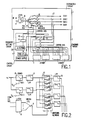
- FIG. 1 is a system diagram showing a subscriber control apparatus comprising one embodiment of the invention.
- This embodiment provides service signal control for four subscribers and can interdict up to sixteen service signals.
- Each service signal is interdicted ("jammed") using a frequency agile oscillator. Groups of four such jamming oscillators are comprised in each jammer module 5.
- the RF distribution circuit 1 provides the path for the signals from the input port 8 to each of four subscriber ports, SUB 1 to SUB 4.
- Broadband cable television signals enter at a common input port 8 and pass through a level setting circuit 9 that may consist of existing attenuators, slope equalizers, and/or automatic gain control circuitry.
- An RF amplifier 10 raises the signal level and also prevents the jamming signals provided by the jammer modules 5, from exiting through the input port 8 and creating interference on the main cable television distribution system.
- the broadband signals then pass through a coupler 11, which directs a sample of the signal to the data receiver 3.
- the data receiver comprises a frequency shift key (FSK) demodulator and detects a plurality of code words sent by the headend to be used in conjunction with the processor to provide control for the subscriber control device, as described below.
- FSK frequency shift key
- coupler 11 then is divided by a signal splitter 13, generating 4 equal amplitude signal paths, one for each subscriber port.
- Each output of the signal splitter passes through a RF switch 14, which is controlled by the control circuit 4 over a control bus (for clarity shown coupled to only one RF switch but understood to provide control to each RF switch).
- Each RF switch 14 is opened to completely block all cable television services from the related subscriber port. When it is closed, all services pass through this point undisturbed.
- Each signal then passes through another RF amplifier 16 which raises the signal to the approximate desired output level, and also provides isolation so that the jamming signals do not travel backward through the circuit and cause interference on other subscriber ports.
- the combiner circuit 2 provides for switching the outputs of the jammer modules 5 to one or more of the subscriber ports under the control of the control circuit. While not forming part of the combiner circuit, jammer modules 5 can be plugged into sockets or otherwise coupled to the combining circuit 2.
- Each of the jammer modules 5 are coupled to output lines 30 which are each coupled to a coupler 27 in the distribution circuit 1.
- Each output line 30 comprises an amplifier 28 and a two pole switch 15 (shown herein for only one output line).
- a jamming signal for one of the subscriber ports first passes through a two pole RF switch 15. In one position, the switch allows for normal operation by allowing jamming signals to pass unaltered to coupler 27. In the second position, the frequency of each oscillator can be calibrated as described below.
- the jamming signals provided by the jammer modules 5 are coupled through couplers 27 to each of the subscriber ports.
- the resulting signals are each a composite of the jamming frequencies and the unaltered cable television signals whereby reception of the unauthorized services is prevented.
- the control circuit 4 comprises a processor 26 which can be a single chip microcontroller. It receives data from the headend through the data receiver 3.
- the data comprises a frequency and authorization table of code words which are processed by the processor 26 to provide the desired control signals to the jammer modules 5, the combining circuit 2 and the distribution circuit 1 to generate jamming frequencies and gate them onto the appropriate subscriber drops.
- Software to achieve the desired switching and control operations described herein can be formulated without undue experimentation, by those skilled in the programming art. Such software can be adapted from automated switching, polling and calibration algorithms currently being used, for example, in conjunction with set top converters in the CATV industry.
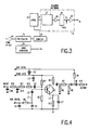
- Each jammer module 5 comprises two circuit boards. Each circuit board, as described in Fig. 2, comprises two voltage controlled oscillators 18. The frequency of each oscillator 18 is determined by a control voltage Vc, as provided by control circuit 4, discussed below. A noise source signal provided by noise generator circuit 34, shown in this example as part of the control circuit (Fig. 3), generates a limited bandwidth of random noise that is distributed to the jammer modules 5.
- Vn is superimposed on the control voltage Vc, causing a random variation of each VCO frequency. This causes the bandwidth of the resulting signal to be spread over a bandwidth equal to the bandwidth of the noise source Vn.
- This signal when added to the cable television, causes interference to the television receiver that, because of the wide bandwidth of the carrier, completely masks the video content of the cable television service.
- the interfering carrier is virtually impossible to remove by any known filtering means without also removing the video content.
- each voltage controlled oscillator 18 passes through respective low pass filters 21 which remove unwanted products generated at harmonics of the desired jamming frequency.
- each signal is then split four ways via a switching network 22, which could be any type of switching arrangement such as a resistor network, thereby providing a jamming signal for each of the four desired subscriber ports.
- the switching control on each board is provided by a logic circuit 19 which responds to control signals provided over the control bus, from control circuit 4.
- the switching circuit 22 can also comprise an RF switch for each jamming signal output which, when closed by the control circuit 4, allows the respective jamming signal to pass.
- the outputs of the RF switches can then be combined and then passed through another low pass filter 23 to remove any harmonic distortion products that may have been generated by switching.
- the outputs of these low pass filters 23 are then directly combined with the corresponding signal outputs from the second board in each respective jammer module 5.
- the signals generated by the jammer modules 5 are fed into the combining circuit 2 which combines the corresponding subscriber jamming singles into a composite jamming signal for each subscriber port.
- frequency control circuit 32 comprises a hybrid R/2R resistor network 27 and is driven by eight outputs to generate analog control voltages for the jamming oscillators 18 in the jammer modules 5. These voltages are buffered by a high speed op-amp 28 and fed to a 1 to 16 analog multiplexer/demultiplexer 29. Each output of the multiplexer represents one of the 16 voltage controlled oscillators 18 (four per jammer module 5). The outputs Vc are buffered by an op-amp 30 and fed to the appropriate jammer module 5. The output of the op-amp is held by a capacitor 31 at the input so that the desired voltage is maintained while the multiplexer is disconnected from a given circuit.
- the processor 26 sequences through each of the oscillators in the jammer modules 5, opening the related switches, setting up the control voltage for the frequency desired, and then closing the switches. Under the direction of the processor 26, the jamming oscillators can be moved in frequency to generate interference on several service signals. Other oscillators can, at the same time, remain fixed on a single service, causing maximum interference.
- the control circuit also provides a frequency setting, circuit 6 comprising an RF amplifier 40 and a fixed divider circuit 33 which are used by the processor 26 to sample the output of each oscillator 18 to measure and set its operating frequency.
- Fig. 4 describes one embodiment of a VCO which can be used in the jammer modules 5.
- the noise voltage can also be injected into the base of the oscillator transistor Q1 causing the amplitude of the jamming signal to vary randomly.
Landscapes
- Engineering & Computer Science (AREA)
- Signal Processing (AREA)
- Computer Networks & Wireless Communication (AREA)
- Multimedia (AREA)
- Two-Way Televisions, Distribution Of Moving Picture Or The Like (AREA)
- Alarm Systems (AREA)
- Noise Elimination (AREA)
Claims (5)
- Teilnehmersteuergerät zum Steuern des Zugriffs auf Kabelfernsehsignale mit:einer Anzahl Interferenzerzeugungsquellen;Mitteln zum Schalten wenigstens einer der Interferenzerzeugungsquellen zu einer Anzahl Teilnehmereingänge; undStörungserzeugungsmitteln zum Ändern der von den Interferenzerzeugungsquellen erzeugten Störsignale, dadurch gekennzeichnet, daß jede Interferenzquelle der Anzahl Interferenzquellen eine Anzahl frequenzagiler Oszillatoren aufweist, wobei die Störungserzeugungsmittel eine beliebige Änderung der Frequenz jedes frequenzagilen Oszillators verursachen, und daß die genannte Teilnehmersteueranordnung Steuermittel aufweist zum Liefern von Steuersignalen in Antwort auf Daten, die zusammen mit den genannten Kabelfernsehsignalen übertragen werden, wobei die genannten Steuersignale die Frequenz jeder der genannten Interferenzerzeugungsquellen und der genannten Schaltmittel steuern.
- Anordnung nach Anspruch 1, wobei die Anzahl frequenzagiler Oszillatoren von einem einzigen Spannungsgenerator gesteuert wird.
- Anordnung nach Anspruch 1, wobei der Zugriff auf Kabelfernsehdienste für viele Teilnehmer durch Überlagerung eines Störungsträgers auf dem Teilnehmereingang innerhalb des Frequenzbandes des zu steuernden Dienstes und wobei jede Interferenzerzeugungsquelle für die vielen Teilnehmereingänge gemeinsam ist.
- Anordnung nach Anspruch 2, wobei die genannten frequenzagilen Oszillatoren in modularer Form vorgesehen sind, und zwar derart, daß eine zusätzliche Störkapazität dadurch zu dem System hinzugefügt werden kann, daß zusätzliche Oszillatormodule hinzugesteckt werden.
- Anordnung nach Anspruch 2, wobei die Steuerspannung der frequenzagilen Oszillatoren mit einer derartigen Bandbreite des beliebigen Geräusches überlagert wird, daß die Ausgangsfrequenz der Oszillatoren innerhalb des gewünschten Dienstbandes beliebig geändert wird.
Applications Claiming Priority (2)
| Application Number | Priority Date | Filing Date | Title |
|---|---|---|---|
| US673872 | 1984-11-21 | ||
| US07/673,872 US5140633A (en) | 1991-03-22 | 1991-03-22 | Cable subscriber control device using shared jamming modules |
Publications (3)
| Publication Number | Publication Date |
|---|---|
| EP0504991A2 EP0504991A2 (de) | 1992-09-23 |
| EP0504991A3 EP0504991A3 (en) | 1993-02-24 |
| EP0504991B1 true EP0504991B1 (de) | 1997-12-17 |
Family
ID=24704422
Family Applications (1)
| Application Number | Title | Priority Date | Filing Date |
|---|---|---|---|
| EP92200717A Expired - Lifetime EP0504991B1 (de) | 1991-03-22 | 1992-03-13 | Teilnehmersteuergerät mit gemeinsamen Störungsmodulen für Kabelfernsehen |
Country Status (5)
| Country | Link |
|---|---|
| US (1) | US5140633A (de) |
| EP (1) | EP0504991B1 (de) |
| JP (1) | JP3373863B2 (de) |
| CA (1) | CA2063517C (de) |
| DE (1) | DE69223535T2 (de) |
Families Citing this family (15)
| Publication number | Priority date | Publication date | Assignee | Title |
|---|---|---|---|---|
| US5463689A (en) * | 1988-03-10 | 1995-10-31 | Scientific-Atlanta | Interdiction method and apparatus with random mode jamming |
| US5289541A (en) * | 1988-03-10 | 1994-02-22 | Scientific-Atlanta, Inc. | Interdiction method and apparatus with constant blanking and variable dwell times |
| US5233652A (en) * | 1991-02-19 | 1993-08-03 | At&T Bell Laboratories | Selective off-premises jamming for premium CATV service |
| US5255318A (en) * | 1991-03-22 | 1993-10-19 | North American Philips Corporation | Expandable cable television subscriber control system |
| US5317635A (en) * | 1992-06-10 | 1994-05-31 | Scientific-Atlanta, Inc. | Interdiction method and apparatus with mode control for variable frequency elements |
| WO1993026126A1 (en) * | 1992-06-10 | 1993-12-23 | Scientific-Atlanta, Inc. | Interdiction method and apparatus with frequency change inhibit function |
| WO1993026127A1 (en) * | 1992-06-10 | 1993-12-23 | Scientific-Atlanta, Inc. | Interdiction method and apparatus with direct memory control of variable frequency elements |
| SE507718C2 (sv) * | 1996-09-13 | 1998-07-06 | Ericsson Telefon Ab L M | Förfarande och anordning för att koda kabeltelevision |
| US6188870B1 (en) * | 1996-10-07 | 2001-02-13 | General Instrument Corporation | Passive interdiction system for scrambling |
| DE29820900U1 (de) | 1998-11-16 | 1999-04-15 | Klein, Patrick, 85716 Unterschleißheim | Elektronischer Bereichsbegrenzer oder Bereichsstörer für Hochfrequenzübertragungen in breitbandigen Übertragungsnetzen |
| US9326705B2 (en) | 2009-09-01 | 2016-05-03 | Adidas Ag | Method and system for monitoring physiological and athletic performance characteristics of a subject |
| US9526419B2 (en) | 2009-09-01 | 2016-12-27 | Adidas Ag | Garment for physiological characteristics monitoring |
| US9545222B2 (en) | 2009-09-01 | 2017-01-17 | Adidas Ag | Garment with noninvasive method and system for monitoring physiological characteristics and athletic performance |
| US20110050216A1 (en) * | 2009-09-01 | 2011-03-03 | Adidas Ag | Method And System For Limiting Interference In Magnetometer Fields |
| US12267151B2 (en) * | 2020-07-02 | 2025-04-01 | Nippon Telegraph And Telephone Corporation | Communication network terminating device, communication system, signal jamming method and signal jamming program |
Family Cites Families (11)
| Publication number | Priority date | Publication date | Assignee | Title |
|---|---|---|---|---|
| US4039954A (en) * | 1975-05-27 | 1977-08-02 | Oak Holland B.V. | Signal distribution device for a cable television |
| GB1554411A (en) * | 1975-08-09 | 1979-10-17 | Communications Patents Ltd | Control systems |
| US4434436A (en) * | 1981-07-13 | 1984-02-28 | Bruce Merrill | Addressable premium channel obfuscation device for cable television systems |
| US4450481A (en) * | 1981-08-25 | 1984-05-22 | E-Com Corporation | Tamper-resistant, expandable communications system |
| US4521809A (en) * | 1982-12-29 | 1985-06-04 | North American Philips Corporation | Method and apparatus for controlling access to selected television programs |
| JPS60245385A (ja) * | 1984-05-18 | 1985-12-05 | Pioneer Electronic Corp | Catvシステムにおける集中視聴制御方式 |
| JPS61139176A (ja) * | 1984-12-10 | 1986-06-26 | Pioneer Electronic Corp | Catvの視聴制御装置 |
| US4825468A (en) * | 1986-10-24 | 1989-04-25 | Broadband Engineering, Inc. | Video noise jammer |
| US5014309A (en) * | 1988-03-10 | 1991-05-07 | Scientific-Atlanta, Inc. | Off-premises cable television channel interdiction method and apparatus |
| US4912760A (en) * | 1988-03-10 | 1990-03-27 | Scientific Atlanta, Inc. | Off-premises cable television channel interdiction method and apparatus |
| WO1991012694A1 (en) * | 1990-02-06 | 1991-08-22 | Scientific-Atlanta, Inc. | Interdiction method and apparatus with variable dwell time |
-
1991
- 1991-03-22 US US07/673,872 patent/US5140633A/en not_active Expired - Lifetime
-
1992
- 1992-03-13 DE DE69223535T patent/DE69223535T2/de not_active Expired - Fee Related
- 1992-03-13 EP EP92200717A patent/EP0504991B1/de not_active Expired - Lifetime
- 1992-03-19 CA CA002063517A patent/CA2063517C/en not_active Expired - Fee Related
- 1992-03-23 JP JP06527192A patent/JP3373863B2/ja not_active Expired - Fee Related
Also Published As
| Publication number | Publication date |
|---|---|
| JP3373863B2 (ja) | 2003-02-04 |
| JPH0591511A (ja) | 1993-04-09 |
| US5140633A (en) | 1992-08-18 |
| EP0504991A2 (de) | 1992-09-23 |
| CA2063517C (en) | 2002-01-08 |
| DE69223535T2 (de) | 1998-06-04 |
| CA2063517A1 (en) | 1992-09-23 |
| EP0504991A3 (en) | 1993-02-24 |
| DE69223535D1 (de) | 1998-01-29 |
Similar Documents
| Publication | Publication Date | Title |
|---|---|---|
| US5140633A (en) | Cable subscriber control device using shared jamming modules | |
| CN1224260C (zh) | 形成有线电视系统一部分的本地网络 | |
| CA2221471C (en) | Settop terminal controlled return path filter for minimizing noise ingress on bidirectional cable systems | |
| US6990203B2 (en) | Cable television setback decoder automatic control | |
| US5020129A (en) | Addressable control system for CATV program distribution | |
| JP3162371B2 (ja) | オフープレミス・ケーブル・テレビジョン・チャンネルの阻止方法および装置 | |
| US5303295A (en) | Enhanced versatility of a program control by a combination of technologies | |
| US4039954A (en) | Signal distribution device for a cable television | |
| NL8004774A (nl) | Draadomroepstelsel met door de abonnee bestuurbare schakelbare programmakeuze. | |
| US7283479B2 (en) | Cable TV system or other similar communication system | |
| US5142574A (en) | Optimum amplitude and frequency of jamming carrier in interdiction program denial system | |
| US4494138A (en) | Segmented upstream management for cable television | |
| USRE29997E (en) | Signal distribution device for a cable television | |
| JPH09500511A (ja) | データを選択的に分配するためのデータ変調装置 | |
| EP0323258B1 (de) | Übertragungsverteilungssystem | |
| US5926547A (en) | Method and apparatus for providing program/component redundancy in headend | |
| US5233652A (en) | Selective off-premises jamming for premium CATV service | |
| US4991206A (en) | Method and apparatus for jamming selected television programs | |
| CA1317013C (en) | Commutation grid | |
| US5255318A (en) | Expandable cable television subscriber control system | |
| JPS608675B2 (ja) | ケ−ブルテレビジヨン用信号分配器 | |
| US6310957B1 (en) | Method and apparatus for interdicting cable television channels | |
| FI77133B (fi) | Signalvaeg foer videoanordning. | |
| WO1998001998A1 (en) | Control system for cable television | |
| JPH0117899Y2 (de) |
Legal Events
| Date | Code | Title | Description |
|---|---|---|---|
| PUAI | Public reference made under article 153(3) epc to a published international application that has entered the european phase |
Free format text: ORIGINAL CODE: 0009012 |
|
| AK | Designated contracting states |
Kind code of ref document: A2 Designated state(s): DE FR GB |
|
| PUAL | Search report despatched |
Free format text: ORIGINAL CODE: 0009013 |
|
| AK | Designated contracting states |
Kind code of ref document: A3 Designated state(s): DE FR GB |
|
| 17P | Request for examination filed |
Effective date: 19930820 |
|
| 17Q | First examination report despatched |
Effective date: 19960212 |
|
| GRAG | Despatch of communication of intention to grant |
Free format text: ORIGINAL CODE: EPIDOS AGRA |
|
| GRAG | Despatch of communication of intention to grant |
Free format text: ORIGINAL CODE: EPIDOS AGRA |
|
| GRAH | Despatch of communication of intention to grant a patent |
Free format text: ORIGINAL CODE: EPIDOS IGRA |
|
| GRAH | Despatch of communication of intention to grant a patent |
Free format text: ORIGINAL CODE: EPIDOS IGRA |
|
| GRAA | (expected) grant |
Free format text: ORIGINAL CODE: 0009210 |
|
| AK | Designated contracting states |
Kind code of ref document: B1 Designated state(s): DE FR GB |
|
| REF | Corresponds to: |
Ref document number: 69223535 Country of ref document: DE Date of ref document: 19980129 |
|
| ET | Fr: translation filed | ||
| RAP4 | Party data changed (patent owner data changed or rights of a patent transferred) |
Owner name: KONINKLIJKE PHILIPS ELECTRONICS N.V. |
|
| REG | Reference to a national code |
Ref country code: FR Ref legal event code: CD |
|
| PLBE | No opposition filed within time limit |
Free format text: ORIGINAL CODE: 0009261 |
|
| STAA | Information on the status of an ep patent application or granted ep patent |
Free format text: STATUS: NO OPPOSITION FILED WITHIN TIME LIMIT |
|
| 26N | No opposition filed | ||
| REG | Reference to a national code |
Ref country code: GB Ref legal event code: IF02 |
|
| PGFP | Annual fee paid to national office [announced via postgrant information from national office to epo] |
Ref country code: GB Payment date: 20090331 Year of fee payment: 18 |
|
| PGFP | Annual fee paid to national office [announced via postgrant information from national office to epo] |
Ref country code: FR Payment date: 20090330 Year of fee payment: 18 Ref country code: DE Payment date: 20090512 Year of fee payment: 18 |
|
| GBPC | Gb: european patent ceased through non-payment of renewal fee |
Effective date: 20100313 |
|
| REG | Reference to a national code |
Ref country code: FR Ref legal event code: ST Effective date: 20101130 |
|
| PG25 | Lapsed in a contracting state [announced via postgrant information from national office to epo] |
Ref country code: FR Free format text: LAPSE BECAUSE OF NON-PAYMENT OF DUE FEES Effective date: 20100331 |
|
| PG25 | Lapsed in a contracting state [announced via postgrant information from national office to epo] |
Ref country code: DE Free format text: LAPSE BECAUSE OF NON-PAYMENT OF DUE FEES Effective date: 20101001 |
|
| PG25 | Lapsed in a contracting state [announced via postgrant information from national office to epo] |
Ref country code: GB Free format text: LAPSE BECAUSE OF NON-PAYMENT OF DUE FEES Effective date: 20100313 |