EP0503908B1 - Einrichtung an einer Tür - Google Patents
Einrichtung an einer Tür Download PDFInfo
- Publication number
- EP0503908B1 EP0503908B1 EP92302052A EP92302052A EP0503908B1 EP 0503908 B1 EP0503908 B1 EP 0503908B1 EP 92302052 A EP92302052 A EP 92302052A EP 92302052 A EP92302052 A EP 92302052A EP 0503908 B1 EP0503908 B1 EP 0503908B1
- Authority
- EP
- European Patent Office
- Prior art keywords
- door
- elongate portion
- glass door
- arrangement
- glass
- Prior art date
- Legal status (The legal status is an assumption and is not a legal conclusion. Google has not performed a legal analysis and makes no representation as to the accuracy of the status listed.)
- Expired - Lifetime
Links
Images


Classifications
-
- E—FIXED CONSTRUCTIONS
- E06—DOORS, WINDOWS, SHUTTERS, OR ROLLER BLINDS IN GENERAL; LADDERS
- E06B—FIXED OR MOVABLE CLOSURES FOR OPENINGS IN BUILDINGS, VEHICLES, FENCES OR LIKE ENCLOSURES IN GENERAL, e.g. DOORS, WINDOWS, BLINDS, GATES
- E06B7/00—Special arrangements or measures in connection with doors or windows
- E06B7/28—Other arrangements on doors or windows, e.g. door-plates, windows adapted to carry plants, hooks for window cleaners
- E06B7/36—Finger guards or other measures preventing harmful access between the door and the door frame
- E06B7/362—Finger guards or other measures preventing harmful access between the door and the door frame the gap between the door and the door frame at the hinge side being constructed in a way to remain too small or too wide to cause injury
-
- E—FIXED CONSTRUCTIONS
- E06—DOORS, WINDOWS, SHUTTERS, OR ROLLER BLINDS IN GENERAL; LADDERS
- E06B—FIXED OR MOVABLE CLOSURES FOR OPENINGS IN BUILDINGS, VEHICLES, FENCES OR LIKE ENCLOSURES IN GENERAL, e.g. DOORS, WINDOWS, BLINDS, GATES
- E06B7/00—Special arrangements or measures in connection with doors or windows
- E06B7/28—Other arrangements on doors or windows, e.g. door-plates, windows adapted to carry plants, hooks for window cleaners
- E06B7/36—Finger guards or other measures preventing harmful access between the door and the door frame
- E06B7/362—Finger guards or other measures preventing harmful access between the door and the door frame the gap between the door and the door frame at the hinge side being constructed in a way to remain too small or too wide to cause injury
- E06B2007/365—Rounded shape at gap, e.g. cylindrical
Definitions
- the present invention relates to a door arrangement, and a method of mounting a door edge attachment, according to the preamble of claim 1.
- U.S. Patent No. 2 619 689 discloses a door arrangement including a pivotally mounted glass door and an edge region adjacent to the door, in which the door is pivotally movable between an open position and a closed position, the majority of the door comprising a generally planar member of substantially constant thickness, the distance of the pivot to the portion of the glass door nearest the edge region being greater than half the width of the generally planar member when the door is in the closed position the arrangement further including an elongate portion connected to the glass door to define an edge portion of the door which is caused to move adjacent to the edge region when the door moves between the closed and open positions and is arranged to be more than half the width of the generally planar member away from the pivot when the door is in the open position.
- the present invention is characterised in that the elongate portion is adhered to the glass door such that movement of the elongate portion away from the glass door is inhibited but sliding movement of the elongate portion along the glass door at the region where the adhesive connects the elongate portion and the door together is permitted.
- the elongate portion may be adhered at one location only to the glass door or, alternatively, the elongate portion may be adhered at a plurality of locations to the glass door.
- the adhering of the elongate portion to the glass door may include a tape wrapped around the edge of the door.
- the tape may provide a physical barrier to inhibit movement of the elongate portion away from the glass door.
- the top of the elongate portion may extend partially within a socket and may be guided for movement within the socket.
- the pivot axis of the glass door may be coincident with the axis of an arcuate portion of the elongate portion.
- the edge region may be comprised by a glass member of the same thickness as the glass door.
- a method of mounting an elongate portion to a door arrangement in which the arrangement includes a pivotally mounted glass door and an edge region adjacent to the door, the door being pivotally movable between an open position and a closed position, the majority of the door comprising a generally planar member of substantially constant thickness, the distance of the pivot to the portion of the glass door nearest the edge region being greater than half the width of the generally planar member when the door is in the closed position such that the elongate portion is connected to the glass door to define an edge portion of the door which is caused to move adjacent to the edge region when the door moves between the closed and open positions and is arranged to be more than half the width of the generally planar member away from the pivot when the door is in the open position, the method is characterised in that the elongate portion is mounted to the glass door by adhering the elongate portion such that movement of the elongate portion away from the glass door is inhibited but sliding movement of the elongate portion along the glass door at the region where
- Figure 1 is a schematic cross-section looking down through a known 10 mm thick glass door 1 and an adjacent glass panel 2.
- the pivot axis 4 is necessarily approximately 18 mm away from the side face of the panel 2 which is much greater than the thickness of the glass and accordingly, when the door is in the open position, there is a gap of 13 mm between the face 5 of the door and the panel 2.
- the edge 12 of the door 10 is surrounded by a groove 13A of a PVC generally cylindrical rod 13.
- the pivot axis 14 of the door is coincident with the longitudinal axis of the rod.
- the diameter of the rod 13 is 25 mm, and the distance between the adjacent outer surface of the rod 13 and the panel 11 is 4.5 mm.
- the axis of rotation of the door will not be exactly coincident with the elongate axis of the rod 13 or tube 40 in which case the gap could open by a minimal amount of from 3 to 4 or from 3 to 5 mm.
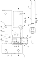
- each of the doors 10 includes a top and bottom vertical pivot mounting 15 and 16 respectively.
- the top mounting 15 comprises a pair of fixed plates 17 (only one of which is shown) which are connected together to abut the front and rear face of the side panel 11 and a top glass panel 18 by bolts 19.
- the top panel 18 has a cut out portion 20 within which is mounted a pivot block 21 by bolts 22 connected to the fixed plates 17.
- the pivot block 21 has a downwardly extending cylindrical pivot lug 23 which extends into a socket 24 formed in the upwardly facing surface of a stainless steel cylindrical housing 25.
- the housing 25 is secured to the door 10 by a pair of bolts 26 which extend to a fixed plate 27 which is welded to the housing 25 which abuts the rear surface of the door and a loose plate 28 which abuts the front surface of the door.
- the housing 25 includes a stop 29 welded thereto which extends between the plates 27 and 28 with which stop the top of the door may abut to locate the door.
- the upwardly extending edge 30 of the door extends through a slot located in the lower portion of the housing to extend partially into a downwardly facing socket 31 located in the lower portion of the housing 25.
- the rod 13 or tube 40 may be a loose fit or a friction fit on the edge 30 of the door.
- the rod 13 or the tube 40 are fixed to the edge 30 by adhesive at one (for instance half way up the door) or more locations.
- a portion of tape may be wrapped around the edge of the door and slightly around each side such that, when the rod or tube is pushed over the edge of the door the tape is engaged.
- the tape may bunch up between the grip with the tube and the edge of the glass, and harden after a time to present a physical barrier to the tube coming off the door.
- the tape may permit sliding of the tube along the edge of the door past the tape.
- the tape may comprise VHB type 9471.
- the tube can be connected at three spaced locations along the edge region of the door and yet still be able to expand or contract by sliding along the edge region.
- the rod 13 or tube 40 may be transparent or translucent.
- the top of the rod 13 or tube 40 extends partially into the socket 31 of the housing. The sides of the socket may guide the movement of the rod 13 or tube 40 with the door and the space between the top of the rod or tube and the top of the socket 31 may allow the rod or tube to expand or contract as the rod or tube is subjected to varying temperatures.
- the centre of the pivot lug 23 which defines the pivot axis is coincident with the longitudinal axis of the generally cylindrical rod 13 or tube 40 such that the outwardly facing surface of the rod 13 or tube 40 is always a constant predetermined small distance from the side panel 11.
- a tube 32 is pivotally mounted about an axis coincident with the centre of the rod 13 by means (not shown).
- the bottom part of the edge 12 of the door extends through a slit 33 in the tube 32, and a reduced section 34 of the rod 13 extends partially into the tube 32 for radial guidance and axial support on a packaging 35.
- the bottom of the rod 13 can be spaced from any packing 35 in order to allow the rod to expand into or retract partially out of the tube as a result of temperature variation.
- This feature is particularly useful where the rod is attached to the door at a location remote from the bottom of the door.
- a block 36 is welded to the rod and extends between and provides support for the door.
- a pair of aluminium bottom rails 37 extend across the bottom region and beneath the bottom region of each door.
- the tube 40 may be mounted and co-operate with other parts of the arrangement in the same way as the rod 13.
Landscapes
- Engineering & Computer Science (AREA)
- Civil Engineering (AREA)
- Structural Engineering (AREA)
- Liquid Crystal (AREA)
- Control And Other Processes For Unpacking Of Materials (AREA)
- Lock And Its Accessories (AREA)
- Specific Sealing Or Ventilating Devices For Doors And Windows (AREA)
- Glass Compositions (AREA)
- Seal Device For Vehicle (AREA)
- Window Of Vehicle (AREA)
Claims (9)
- Eine eine schwenkbar gelagerte Glastür (10) und einen Randbereich (11) benachbart zu der Tür umfassende Türanordnung, bei der die Tür schwenkbar zwischen einer offenen Stellung und einer geschlossenen Stellung bewegbar ist, wobei der Großteil der Tür ein im allgemeinen ebenes Teil (10) im wesentlichen konstanter Stärke umfaßt und der Abstand des Schwenklagers/Scharniers (14) zu dem dem Randbereich (10) nächsten Abschnitt der Glastür größer als die halbe Stärke des im wesentlichen ebenen Teils (10) bei sich in geschlossener Stellung befindlicher Tür ist, wobei die Anordnung weiter einen länglichen Abschnitt umfaßt, der mit der Glastür verbunden ist, um einen Randabschnitt (13, 40) der Tür zu bestimmen, der sich benachbart zu dem Randbereich (11) bewegen soll, wenn die Tür sich zwischen der geschlossenen und geöffneten Stellung bewegt, und so angeordnet ist, daß er mehr als die Hälfte der Stärke des im allgemeinen ebenen Teils (10) von dem Schwenkzapfen (14) entfernt ist, wenn sich die Tür in geöffneter Stellung befindet, dadurch gekennzeichnet, daß der längliche Abschnitt an der Glastür so befestigt ist, daß die Bewegung des länglichen Abschnittes von der Glastür weg verhindert wird, aber eine Gleitbewegung des länglichen Abschnittes entlang der Glastür in dem Bereich, in dem die Befestigung den länglichen Abschnitt und die Tür miteinander verbindet, möglich ist.
- Eine Anordnung nach Anspruch 1, bei der der längliche Abschnitt an einer Stelle nur mit der Glastür befestigt ist.
- Eine Anordnung nach Anspruch 1, bei der der längliche Abschnitt an einer Mehrzahl Stellen mit der Glastür befestigt ist.
- Eine Anordnung nach einem der vorhergehenden Ansprüche, bei der die Befestigung ein um den Rand der Tür gewickeltes Band umfaßt.
- Eine Anordnung nach Anspruch 4, bei der das Band eine physische Trennung bildet, um eine Bewegung des länglichen Abschnittes von der Glastür weg zu verhindern.
- Eine Anordnung nach einem der vorhergehenden Ansprüche, bei der das obere Teil des länglichen Abschnittes sich teilweise in einer Lageraufnahme (31) erstreckt und zur Bewegung darin geführt ist.
- Eine Anordnung nach einem der vorhergehenden Ansprüche, bei der die Schwenkachse der Glastür mit der Achse eines bogenförmigen Abschnittes des länglichen Abschnittes übereinstimmt.
- Eine Anordnung nach einem der vorhergehenden Ansprüche, bei der der Randbereich (11) in einem Glasteil der gleichen Stärke wie die Glastür enthalten ist.
- Ein Verfahren zum Anbringen eines länglichen Abschnittes an einer Türanordnung, wobei letztere eine schwenkbar gelagerte Glastür (10) und einen benachbart zu der Tür befindlichen Randbereich (11) umfaßt, wobei die Tür schwenkbar zwischen einer geöffneten Stellung und einer geschlossenen Stellung beweglich ist, wobei der Großteil der Tür ein im allgemeinen ebenes Teil (10) im wesentlichen konstanter Stärke umfaßt, wobei der Abstand des Schwenklagers/Scharniers (14) zu dem dem Randbereich (11) nahesten Abschnitt der Glastür größer als die halbe Stärke des im wesentlichen ebenen Teils (10) bei sich in geschlossener Stellung befindlicher Tür ist, so daß der längliche Abschnitt mit der Glastür verbunden wird, um einen Randabschnitt (13, 40) der Tür zu bestimmen, der dazu gebracht wird, sich benachbart zu dem Randbereich (11) zu bewegen, wenn die Tür sich zwischen der geschlossenen und geöffneten Stellung bewegt, und so angeordnet wird, daß er mehr als die Hälfte der Stärke des im allgemeinen ebenen Teils (10) von dem Schwenkzapfen (14) entfernt ist, wenn sich die Tür in geöffneter Stellung befindet, dadurch gekennzeichnet, daß das Verfahren das Anbringen des länglichen Abschnitts an der Glastür durch Befestigen des länglichen Abschnitts derart umfaßt, daß eine Bewegung des länglichen Abschnittes von der Glastür weg verhindert wird, aber eine Gleitbewegung des länglichen Abschnittes entlang der Glastür in dem Bereich, in dem das Befestigungsmittel den länglichen Abschnitt und die Tür miteinander verbindet, ermöglicht wird.
Applications Claiming Priority (2)
| Application Number | Priority Date | Filing Date | Title |
|---|---|---|---|
| GB919105182A GB9105182D0 (en) | 1991-03-12 | 1991-03-12 | Improvements in or relating to doors |
| GB9105182 | 1991-03-12 |
Publications (2)
| Publication Number | Publication Date |
|---|---|
| EP0503908A1 EP0503908A1 (de) | 1992-09-16 |
| EP0503908B1 true EP0503908B1 (de) | 1996-05-15 |
Family
ID=10691404
Family Applications (1)
| Application Number | Title | Priority Date | Filing Date |
|---|---|---|---|
| EP92302052A Expired - Lifetime EP0503908B1 (de) | 1991-03-12 | 1992-03-11 | Einrichtung an einer Tür |
Country Status (4)
| Country | Link |
|---|---|
| EP (1) | EP0503908B1 (de) |
| AT (1) | ATE138152T1 (de) |
| DE (1) | DE69210661T2 (de) |
| GB (1) | GB9105182D0 (de) |
Families Citing this family (2)
| Publication number | Priority date | Publication date | Assignee | Title |
|---|---|---|---|---|
| US8752335B2 (en) * | 2012-03-27 | 2014-06-17 | Rite-Hite Holding Corporation | Bulb seals for doors |
| CN102817530A (zh) * | 2012-07-29 | 2012-12-12 | 张善元 | 防夹伤安全教室门 |
Family Cites Families (3)
| Publication number | Priority date | Publication date | Assignee | Title |
|---|---|---|---|---|
| US2619689A (en) * | 1950-09-19 | 1952-12-02 | Harold G Parrott | Glass door guard |
| CH577620A5 (de) * | 1973-03-05 | 1976-07-15 | Ehret Werner | |
| FR2381889A1 (fr) * | 1977-02-23 | 1978-09-22 | Placal | Porte de communication eliminant les risques de mutilation |
-
1991
- 1991-03-12 GB GB919105182A patent/GB9105182D0/en active Pending
-
1992
- 1992-03-11 AT AT92302052T patent/ATE138152T1/de not_active IP Right Cessation
- 1992-03-11 DE DE69210661T patent/DE69210661T2/de not_active Expired - Lifetime
- 1992-03-11 EP EP92302052A patent/EP0503908B1/de not_active Expired - Lifetime
Also Published As
| Publication number | Publication date |
|---|---|
| DE69210661D1 (de) | 1996-06-20 |
| DE69210661T2 (de) | 1997-01-02 |
| GB9105182D0 (en) | 1991-04-24 |
| EP0503908A1 (de) | 1992-09-16 |
| ATE138152T1 (de) | 1996-06-15 |
Similar Documents
| Publication | Publication Date | Title |
|---|---|---|
| EP0619412A3 (de) | Vorrichtung zur Abdeckung einer Fenster- oder Türöffnung. | |
| US4124955A (en) | Automatic closure | |
| FR2707331B1 (fr) | Verrou de porte à gonflement. | |
| IT9048598A0 (it) | Complesso di cerniera per porte autochiudenti a camme. | |
| US4165553A (en) | Sliding door safety device | |
| US6311432B1 (en) | Safety device for doors | |
| IT8020883A0 (it) | Giunto a cerniera coperto per porte, coperchi a cerniera esimili. | |
| EP0503908A1 (de) | Einrichtung an einer Tür | |
| FR2664644B1 (fr) | Dispositif de motorisation pour la manóoeuvre electrique des fenetres ou portes a vantail coulissant. | |
| EP0932740A1 (de) | Scharnier, speziell für türen oder fenster | |
| GB2246163A (en) | Stays | |
| US5224916A (en) | Door moving mechanism for a cutting machine | |
| KR20050036822A (ko) | 두 대의 굴절차량 또는 차량 객실 사이 통로의 벨로스의내벽 커버 | |
| GB2263306B (en) | Door drive for an up and over door, sectional door or sliding door, especially a garage door | |
| FR2661940B2 (fr) | Charniere a arret de porte integre pour portes de vehicules ou autres ouvrants. | |
| EP0651848B1 (de) | Türschliesser | |
| WO1999061742A8 (en) | Slatted door | |
| US5813091A (en) | Safety device for a door | |
| FR2668533B1 (fr) | Porte relevante basculante sans debord exterieur a mouvement compense. | |
| GB2310681A (en) | Adjustable safety device for a pivoting door, to shield the gap between the door edge and the frame. | |
| GB2281346A (en) | Friction stay | |
| IT7920913A0 (it) | Struttura a profilati per porte scorrevoli, finestre scorrevoli esimili; nonche' porta e finestra scorrevoli o simile utilizzante la struttura detta. | |
| KR970029729A (ko) | 테이프 레코더의 프론트 도어 잠금 장치 | |
| FR2696051B1 (fr) | Armoire à battant de porte équipé d'un détecteur de fermeture. | |
| GB2169952A (en) | A stay |
Legal Events
| Date | Code | Title | Description |
|---|---|---|---|
| PUAI | Public reference made under article 153(3) epc to a published international application that has entered the european phase |
Free format text: ORIGINAL CODE: 0009012 |
|
| AK | Designated contracting states |
Kind code of ref document: A1 Designated state(s): AT BE CH DE DK ES FR GB GR IT LI LU MC NL PT SE |
|
| 17P | Request for examination filed |
Effective date: 19930302 |
|
| 17Q | First examination report despatched |
Effective date: 19930903 |
|
| GRAH | Despatch of communication of intention to grant a patent |
Free format text: ORIGINAL CODE: EPIDOS IGRA |
|
| GRAA | (expected) grant |
Free format text: ORIGINAL CODE: 0009210 |
|
| AK | Designated contracting states |
Kind code of ref document: B1 Designated state(s): AT BE CH DE DK ES FR GB GR IT LI LU MC NL PT SE |
|
| PG25 | Lapsed in a contracting state [announced via postgrant information from national office to epo] |
Ref country code: IT Free format text: LAPSE BECAUSE OF FAILURE TO SUBMIT A TRANSLATION OF THE DESCRIPTION OR TO PAY THE FEE WITHIN THE PRE;WARNING: LAPSES OF ITALIAN PATENTS WITH EFFECTIVE DATE BEFORE 2007 MAY HAVE OCCURRED AT ANY TIME BEFORE 2007. THE CORRECT EFFECTIVE DATE MAY BE DIFFERENT FROM THE ONE RECORDED.SCRIBED TIME-LIMIT Effective date: 19960515 Ref country code: DK Effective date: 19960515 Ref country code: GR Free format text: LAPSE BECAUSE OF FAILURE TO SUBMIT A TRANSLATION OF THE DESCRIPTION OR TO PAY THE FEE WITHIN THE PRESCRIBED TIME-LIMIT Effective date: 19960515 Ref country code: ES Free format text: THE PATENT HAS BEEN ANNULLED BY A DECISION OF A NATIONAL AUTHORITY Effective date: 19960515 Ref country code: AT Effective date: 19960515 Ref country code: NL Free format text: LAPSE BECAUSE OF FAILURE TO SUBMIT A TRANSLATION OF THE DESCRIPTION OR TO PAY THE FEE WITHIN THE PRESCRIBED TIME-LIMIT Effective date: 19960515 Ref country code: LI Effective date: 19960515 Ref country code: CH Effective date: 19960515 |
|
| REF | Corresponds to: |
Ref document number: 138152 Country of ref document: AT Date of ref document: 19960615 Kind code of ref document: T |
|
| REF | Corresponds to: |
Ref document number: 69210661 Country of ref document: DE Date of ref document: 19960620 |
|
| PG25 | Lapsed in a contracting state [announced via postgrant information from national office to epo] |
Ref country code: SE Effective date: 19960815 |
|
| PG25 | Lapsed in a contracting state [announced via postgrant information from national office to epo] |
Ref country code: PT Effective date: 19960816 |
|
| ET | Fr: translation filed | ||
| NLV1 | Nl: lapsed or annulled due to failure to fulfill the requirements of art. 29p and 29m of the patents act | ||
| REG | Reference to a national code |
Ref country code: CH Ref legal event code: PL |
|
| PLBE | No opposition filed within time limit |
Free format text: ORIGINAL CODE: 0009261 |
|
| PG25 | Lapsed in a contracting state [announced via postgrant information from national office to epo] |
Ref country code: LU Free format text: LAPSE BECAUSE OF NON-PAYMENT OF DUE FEES Effective date: 19970331 |
|
| 26N | No opposition filed | ||
| PG25 | Lapsed in a contracting state [announced via postgrant information from national office to epo] |
Ref country code: MC Effective date: 19970930 |
|
| REG | Reference to a national code |
Ref country code: GB Ref legal event code: IF02 |
|
| PGFP | Annual fee paid to national office [announced via postgrant information from national office to epo] |
Ref country code: FR Payment date: 20100402 Year of fee payment: 19 |
|
| PGFP | Annual fee paid to national office [announced via postgrant information from national office to epo] |
Ref country code: DE Payment date: 20100419 Year of fee payment: 19 |
|
| PGFP | Annual fee paid to national office [announced via postgrant information from national office to epo] |
Ref country code: BE Payment date: 20100506 Year of fee payment: 19 |
|
| PGFP | Annual fee paid to national office [announced via postgrant information from national office to epo] |
Ref country code: GB Payment date: 20110408 Year of fee payment: 20 |
|
| BERE | Be: lapsed |
Owner name: *JONES CHRISTOPHER SEAN Effective date: 20110331 |
|
| REG | Reference to a national code |
Ref country code: FR Ref legal event code: ST Effective date: 20111130 |
|
| PG25 | Lapsed in a contracting state [announced via postgrant information from national office to epo] |
Ref country code: BE Free format text: LAPSE BECAUSE OF NON-PAYMENT OF DUE FEES Effective date: 20110331 |
|
| PG25 | Lapsed in a contracting state [announced via postgrant information from national office to epo] |
Ref country code: FR Free format text: LAPSE BECAUSE OF NON-PAYMENT OF DUE FEES Effective date: 20110331 Ref country code: DE Free format text: LAPSE BECAUSE OF NON-PAYMENT OF DUE FEES Effective date: 20111001 |
|
| REG | Reference to a national code |
Ref country code: DE Ref legal event code: R119 Ref document number: 69210661 Country of ref document: DE Effective date: 20111001 |
|
| REG | Reference to a national code |
Ref country code: GB Ref legal event code: PE20 Expiry date: 20120310 |
|
| PG25 | Lapsed in a contracting state [announced via postgrant information from national office to epo] |
Ref country code: GB Free format text: LAPSE BECAUSE OF EXPIRATION OF PROTECTION Effective date: 20120310 |