EP0503552A1 - Abschaltsystem für Kernwasserreaktor - Google Patents
Abschaltsystem für Kernwasserreaktor Download PDFInfo
- Publication number
- EP0503552A1 EP0503552A1 EP92104053A EP92104053A EP0503552A1 EP 0503552 A1 EP0503552 A1 EP 0503552A1 EP 92104053 A EP92104053 A EP 92104053A EP 92104053 A EP92104053 A EP 92104053A EP 0503552 A1 EP0503552 A1 EP 0503552A1
- Authority
- EP
- European Patent Office
- Prior art keywords
- water
- reactor
- inlet
- unit
- circulation system
- Prior art date
- Legal status (The legal status is an assumption and is not a legal conclusion. Google has not performed a legal analysis and makes no representation as to the accuracy of the status listed.)
- Withdrawn
Links
- XLYOFNOQVPJJNP-UHFFFAOYSA-N water Substances O XLYOFNOQVPJJNP-UHFFFAOYSA-N 0.000 title claims abstract description 57
- 239000000446 fuel Substances 0.000 claims abstract description 35
- 230000000712 assembly Effects 0.000 claims abstract description 18
- 238000000429 assembly Methods 0.000 claims abstract description 18
- 239000006096 absorbing agent Substances 0.000 claims abstract description 9
- 238000005192 partition Methods 0.000 claims description 10
- 230000002093 peripheral effect Effects 0.000 claims 1
- ZOXJGFHDIHLPTG-UHFFFAOYSA-N Boron Chemical compound [B] ZOXJGFHDIHLPTG-UHFFFAOYSA-N 0.000 description 12
- 229910052796 boron Inorganic materials 0.000 description 12
- KGBXLFKZBHKPEV-UHFFFAOYSA-N boric acid Chemical compound OB(O)O KGBXLFKZBHKPEV-UHFFFAOYSA-N 0.000 description 4
- 229910000831 Steel Inorganic materials 0.000 description 3
- 239000004327 boric acid Substances 0.000 description 3
- 239000010959 steel Substances 0.000 description 3
- 230000004888 barrier function Effects 0.000 description 1
- 230000000903 blocking effect Effects 0.000 description 1
- 239000002826 coolant Substances 0.000 description 1
- 238000011161 development Methods 0.000 description 1
- 230000018109 developmental process Effects 0.000 description 1
- 238000010790 dilution Methods 0.000 description 1
- 239000012895 dilution Substances 0.000 description 1
- 238000000034 method Methods 0.000 description 1
- 239000000203 mixture Substances 0.000 description 1
- 230000009257 reactivity Effects 0.000 description 1
- 239000000126 substance Substances 0.000 description 1
Images

Classifications
-
- G—PHYSICS
- G21—NUCLEAR PHYSICS; NUCLEAR ENGINEERING
- G21C—NUCLEAR REACTORS
- G21C15/00—Cooling arrangements within the pressure vessel containing the core; Selection of specific coolants
- G21C15/18—Emergency cooling arrangements; Removing shut-down heat
-
- G—PHYSICS
- G21—NUCLEAR PHYSICS; NUCLEAR ENGINEERING
- G21C—NUCLEAR REACTORS
- G21C9/00—Emergency protection arrangements structurally associated with the reactor, e.g. safety valves provided with pressure equalisation devices
- G21C9/02—Means for effecting very rapid reduction of the reactivity factor under fault conditions, e.g. reactor fuse; Control elements having arrangements activated in an emergency
- G21C9/033—Means for effecting very rapid reduction of the reactivity factor under fault conditions, e.g. reactor fuse; Control elements having arrangements activated in an emergency by an absorbent fluid
-
- G—PHYSICS
- G21—NUCLEAR PHYSICS; NUCLEAR ENGINEERING
- G21C—NUCLEAR REACTORS
- G21C1/00—Reactor types
- G21C1/04—Thermal reactors ; Epithermal reactors
- G21C1/06—Heterogeneous reactors, i.e. in which fuel and moderator are separated
- G21C1/08—Heterogeneous reactors, i.e. in which fuel and moderator are separated moderator being highly pressurised, e.g. boiling water reactor, integral super-heat reactor, pressurised water reactor
- G21C1/088—Inherently safe boiling water reactors
-
- G—PHYSICS
- G21—NUCLEAR PHYSICS; NUCLEAR ENGINEERING
- G21C—NUCLEAR REACTORS
- G21C1/00—Reactor types
- G21C1/04—Thermal reactors ; Epithermal reactors
- G21C1/06—Heterogeneous reactors, i.e. in which fuel and moderator are separated
- G21C1/08—Heterogeneous reactors, i.e. in which fuel and moderator are separated moderator being highly pressurised, e.g. boiling water reactor, integral super-heat reactor, pressurised water reactor
- G21C1/09—Pressure regulating arrangements, i.e. pressurisers
-
- G—PHYSICS
- G21—NUCLEAR PHYSICS; NUCLEAR ENGINEERING
- G21C—NUCLEAR REACTORS
- G21C13/00—Pressure vessels; Containment vessels; Containment in general
- G21C13/02—Details
- G21C13/024—Supporting constructions for pressure vessels or containment vessels
-
- Y—GENERAL TAGGING OF NEW TECHNOLOGICAL DEVELOPMENTS; GENERAL TAGGING OF CROSS-SECTIONAL TECHNOLOGIES SPANNING OVER SEVERAL SECTIONS OF THE IPC; TECHNICAL SUBJECTS COVERED BY FORMER USPC CROSS-REFERENCE ART COLLECTIONS [XRACs] AND DIGESTS
- Y02—TECHNOLOGIES OR APPLICATIONS FOR MITIGATION OR ADAPTATION AGAINST CLIMATE CHANGE
- Y02E—REDUCTION OF GREENHOUSE GAS [GHG] EMISSIONS, RELATED TO ENERGY GENERATION, TRANSMISSION OR DISTRIBUTION
- Y02E30/00—Energy generation of nuclear origin
- Y02E30/30—Nuclear fission reactors
Definitions
- the invention relates to a nuclear reactor according to the precharacterising part of claim 1.
- a nuclear reactor of this kind is described, inter alia, in ABB Journal 2/90 and known under the name PIUS (Process Inherent Ultimate Safety).
- PIUS Process Inherent Ultimate Safety
- boron in the form of a water-soluble boron-containing substance, such as boric acid, H3BO3.
- one or more heat exchangers and one or more circulation pumps are included in the mentioned circulation system. Outside the pool the circulation system is divided into a number of parallel-connected branches, each of which contains a heat exchanger and a circulation pump. From other publications it is known to arrange heat exchangers and circulation pumps inside the pool.
- the invention aims at developing an improved arrangement of the diffusers such that their effectiveness and accessibility for exchange and adjustment are increased.
- the invention suggests a nuclear reactor according to the introductory part of claim 1, which is characterized by the features of the characterizing part of claim 1.
- the diffusers By the arrangement of the diffusers according to the invention, they can easily, preferably in connection with refuelling, be made available for exchange and for adjustment of dimensions, so that the dimensions can be adapted to provide a desired function of the diffusers.
- the use of several diffusers below each one of the mentioned fuel assemblies means that the height of the reactor unit can be reduced.
- the diffuser/diffusers below each one of the fuel assemblies is/are arranged in an inlet box or other inlet unit for the water in the circulation system.
- the inlet box or inlet unit may be secured to the respective fuel assembly or only placed below the fuel assembly and handled as a separate unit.
- an inlet space for the water which is common to and communicates with the inlet units.
- a buffer space which is separated from the inlet space by a partition and which communicates with the inlet units via individual pipes which penetrate the partition and extend through the inlet space.
- each one of the individual pipes is formed with an upper part fixed to an inlet unit and a lower part fixed to the partition. These two parts are adapted, during operation of the reactor, to form with each other a connection which is sealed to the surroundings and to be separable when with-drawing the fuel assemblies from the reactor core.
- diffusers which are located in the periphery of the reactor core are arranged with a smaller flow area than diffusers located in the centre of the reactor core.
- This embodiment is specially designed to be used in cores with fuel assemblies with fuel channels around the bundle of fuel rods. The measure allows the coolant flow to be adapted to the locally prevailing power density in the core.
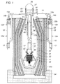
- the reactor according to Figures 1 and 2 has a reactor unit 10 comprising a reactor core 11.
- the reactor unit is part of a circulation system 14 for water which along part of its path is divided into a number of parallel-connected branches, each one with a heat exchanger 12 and a circulation pump 13.
- the reactor unit is arranged in a pool with water 15 with a high content of neutron absorber.
- the water 16 in the circulation system 14 has a considerably lower content of neutron absorber than the water 15 in the pool, and between the water 16 in the circulation system 14 and the water 15 in the pool, interfaces are maintained in density locks 17a and 17b arranged in a lower and a higher level, respectively, in the reactor unit.
- the heat which is generated in the reactor core is taken out for useful purposes via the water 16 in the circulation system 14 and the heat exchangers 12.
- the water 15 in the pool penetrates via the density locks into the reactor unit and is mixed with the water 16 such that the mixture's content of neutron absorber becomes sufficiently high to prevent criticality.
- the reactor vessel 30 constitutes a pressure vessel in the form of a concrete monolith. It is provided with an embedded (cast-in) steel layer 31 as extra leakage barrier and with a steel lining 32. It is prestressed with prestess cables 33. Certain of these, 33a, are utilized to secure the concrete monolith to the bottom plate 34 of the reactor building and others, 33b, to secure it to an upper part 35-36 of steel. The uppermost part 36 of the vessel is detachably fixed to the part 35, inter alia for refuelling.
- the water 15 in the pool in the concrete vessel contains a high content, for example about 2000 ppm, of boron in the form of boric acid.
- the water is cooled by heat exchangers placed inside and outside the pool such that the temperature is normally maintained at about 50°C.
- the concrete vessel is cooled by the water in the pool and is always cold.
- the pressure in the whole system is achieved with steam in pressurized steam volume 37.
- the steam is generated in an external circuit (not shown).
- the reactivity (power) in the reactor is controlled with the aid of the boron content and the temperature of the water 16.
- the boron content in this water is below 400 ppm during continuous operation.
- the flowing boron water 16 is heated in the reactor core 11 from 260°C to 290°C. After having left the core, the water rises upwards through the riser 38.
- the cooled water 16 flows via four circulation pipes 14b, of which two are shown in Figure 1, back to the reactor vessel and into the downcomer 40. However, before that, the water 16 is led into an inlet chamber 18 before it passes into the downcomer. From the downcomer the flow continues through an annular gap 41 on the outside of the riser 38 and enters the core thus completing the circuit in the circulation system 14.
- the riser 38, the annular gap 39, the downcomer 40 and the annular gap 41 constitute in all essentials the internal flow-controlling parts in the reactor.
- the water 15 in the pool with a high boron content and the water 16 in the circulation system with a low boron content are maintained, during operation, stably separated in predetermined positions in the density locks 17a and 17b by keeping the pump circulation in the circuit 14 within definite limits. If the pump circulation should be too small or too great, water 15 from the pool with a high boron content would penetrate in through the lower density lock 17a and through the upper density lock 17b, respectively, resulting in the nuclear reaction in the reactor core being stopped.
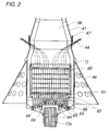
- Each density lock consists of a bundle of long pipes, open at both ends, which at their lower end are welded to a perforated end plate.
- numeral 44 designates core instrumentation, 46 a perforated support skirt for the parts of the reactor which are located in the concrete vessel, 47 a flange which can be opened, for example in connection with refuelling, 45 a number of connecting pipes between the steam volume 37 and cold water with a high boron content in the pool, 54 the level of the latter water in the connecting pipes, 48 and 51 two pipes which form between them an annular gap 52 extending from the upper edge 43 of the riser 38/the annular gap 39 down to the upper density lock 17b.
- the annular gap 52 communicates with annular gap 39 via the space 53 with water with a low boron content around the inlet chamber 18.
- the reactor core 11 comprises a large number, for example over 200, of fuel assemblies 60, each on comprising a large number, for example 18 x 18, of fuel rods.
- the fuel assemblies are arranged on a core supporting plate 61.
- An inlet unit 62 for water from the gap 41 is, in the illustrated embodiment, secured to the lower inlet on each fuel assembly and is together with the fuel assembly withdrawable from the core supporting plate.
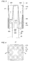
- the inlet 62a (see Figures 3 to 5) of the inlet units communicates openly with a common inlet space 63, arranged below them, for the water 16 from the gap 41, and their outlet 62b communicates openly with the space between the fuel rods in the fuel assemblies.
- a buffer volume 64 which contains water with a low boron content. This space is separated from the inlet space 63 by a partition 65.
- the buffer volume is arranged in communicating connection with each one of the inlet units in a manner which will be described below via individual pipes 66 which penetrate the partition 65 and extend through the inlet space 63.
- each such pipe has an upper part 66a secured to the inlet unit in the form of an inlet box, and a lower part 66b secured to the partition 65.
- each inlet box is secured to its fuel assembly in the illustrated embodiment, the inlet box can be lifted out of the core together with the fuel assembly. In the case where the inlet box is placed below the fuel assembly without being secured to it, the inlet box can be lifted out of the core as a separate unit.
- Each inlet box 62 in the case exemplified in Figures 3 and 4, contains eight diffusers 67.
- Each diffuser has a circular cross section perpendicular to its symmetry axis, that is perpendicular to the direction of flow of the water through the diffuser.
- the diameter where the cross section is largest, at 67b may suitably be 1.03-2.5, preferably 1.2-2.0 times as large as where the cross section is smallest, at 67a.
- the water 16 from the gap 41 and the inlet space 63. during normal operation, passes into the inlet boxes 62 at their inlets 62a and out at their outlets 62b and thus passes each diffuser 67 from its inlet 67a to its outlet 67b.
- the water 15 in the pool penetrates via the density lock 17a into the buffer volume 64, from there through the pipes 66 into a space 62c located in each inlet box and surrounded by the diffusers, from there via holes 67c provided in the diffusers into the diffusers and from there into the fuel assemblies 60 in the reactor core 11.
- FIG 5 shows an example of an inlet unit 62 with only one diffuser 67 for each fuel assembly of a nuclear reactor according to the invention.
- the pipe 66 is arranged centrally in the diffuser without being secured to the inlet unit. It has a cross section, the upper part of which is tapering in a vertical direction.
- the holes 66d which connect the interior of the pipe 66 to the diffuser 67, and the function of which is analogous to the function of the holes 67c in Figure 3, are arranged in the pipe 66.
- the inlet unit can be lifted out of the core together with the fuel assembly.
- a hood 68 for a gas cushion 69 is arranged in the buffer volume 64, the gas cushion blocking the lower density lock 17a upon start-up of the rector, when the flow in the circulation system 14 is low and the boric acid therein is diluted with pure water until criticality is attained. With continued dilution, the temperature of the water in the circulation system is increased, and the pump speed is adjusted such that the gas cushion can be removed.
Landscapes
- Physics & Mathematics (AREA)
- Engineering & Computer Science (AREA)
- Plasma & Fusion (AREA)
- General Engineering & Computer Science (AREA)
- High Energy & Nuclear Physics (AREA)
- Structure Of Emergency Protection For Nuclear Reactors (AREA)
Applications Claiming Priority (2)
| Application Number | Priority Date | Filing Date | Title |
|---|---|---|---|
| SE9100720 | 1991-03-11 | ||
| SE9100720A SE468148B (sv) | 1991-03-11 | 1991-03-11 | Kaernreaktor daer en diffusor i cirkulationskretsen foer vatten |
Publications (1)
| Publication Number | Publication Date |
|---|---|
| EP0503552A1 true EP0503552A1 (de) | 1992-09-16 |
Family
ID=20382122
Family Applications (1)
| Application Number | Title | Priority Date | Filing Date |
|---|---|---|---|
| EP92104053A Withdrawn EP0503552A1 (de) | 1991-03-11 | 1992-03-10 | Abschaltsystem für Kernwasserreaktor |
Country Status (2)
| Country | Link |
|---|---|
| EP (1) | EP0503552A1 (de) |
| SE (1) | SE468148B (de) |
Cited By (3)
| Publication number | Priority date | Publication date | Assignee | Title |
|---|---|---|---|---|
| DE19838415A1 (de) * | 1998-08-24 | 2000-03-09 | Siemens Ag | Einrichtung und Verfahren zum Einspeisen einer Borlösung in den Reaktordruckbehälter eines Kernkraftwerks |
| CN101572128B (zh) * | 2009-06-16 | 2011-09-14 | 哈尔滨工程大学 | 均压式密度锁 |
| EP3306619A4 (de) * | 2015-06-01 | 2019-01-16 | State Atomic Energy Corporation "Rosatom" on Behalf of The Russian Federation | Vorrichtung für passiven schutz eines kernreaktors |
Citations (3)
| Publication number | Priority date | Publication date | Assignee | Title |
|---|---|---|---|---|
| FR2502828A1 (fr) * | 1981-03-30 | 1982-10-01 | Asea Atom Ab | Dispositif de securite pour assurer le refroidissement d'une installation nucleaire |
| EP0271890A1 (de) * | 1986-12-17 | 1988-06-22 | Ab Asea-Atom | Kernreaktor |
| EP0359716A2 (de) * | 1988-09-15 | 1990-03-21 | FINMECCANICA S.p.A. AZIENDA ANSALDO | Druckwasserkernreaktor mit intrinsischer Sicherheit |
-
1991
- 1991-03-11 SE SE9100720A patent/SE468148B/sv not_active IP Right Cessation
-
1992
- 1992-03-10 EP EP92104053A patent/EP0503552A1/de not_active Withdrawn
Patent Citations (3)
| Publication number | Priority date | Publication date | Assignee | Title |
|---|---|---|---|---|
| FR2502828A1 (fr) * | 1981-03-30 | 1982-10-01 | Asea Atom Ab | Dispositif de securite pour assurer le refroidissement d'une installation nucleaire |
| EP0271890A1 (de) * | 1986-12-17 | 1988-06-22 | Ab Asea-Atom | Kernreaktor |
| EP0359716A2 (de) * | 1988-09-15 | 1990-03-21 | FINMECCANICA S.p.A. AZIENDA ANSALDO | Druckwasserkernreaktor mit intrinsischer Sicherheit |
Cited By (4)
| Publication number | Priority date | Publication date | Assignee | Title |
|---|---|---|---|---|
| DE19838415A1 (de) * | 1998-08-24 | 2000-03-09 | Siemens Ag | Einrichtung und Verfahren zum Einspeisen einer Borlösung in den Reaktordruckbehälter eines Kernkraftwerks |
| CN101572128B (zh) * | 2009-06-16 | 2011-09-14 | 哈尔滨工程大学 | 均压式密度锁 |
| EP3306619A4 (de) * | 2015-06-01 | 2019-01-16 | State Atomic Energy Corporation "Rosatom" on Behalf of The Russian Federation | Vorrichtung für passiven schutz eines kernreaktors |
| US10643755B2 (en) | 2015-06-01 | 2020-05-05 | State Atomic Energy Corporation “Rosatom” On Behalf Of The Russian Federation | Device for passive protection of a nuclear reactor |
Also Published As
| Publication number | Publication date |
|---|---|
| SE9100720D0 (sv) | 1991-03-11 |
| SE468148B (sv) | 1992-11-09 |
| SE9100720L (sv) | 1992-09-12 |
Similar Documents
| Publication | Publication Date | Title |
|---|---|---|
| US3182002A (en) | Liquid cooled nuclear reactor with improved heat exchange arrangement | |
| US4526742A (en) | Nuclear reactor plant | |
| US5112569A (en) | Intrinsic-safety nuclear reactor of the pressurized water type | |
| US4115192A (en) | Fast neutron nuclear reactor | |
| EP2571028B1 (de) | Reaktorbehälterreflektor mit integriertem Durchfluss | |
| US4696792A (en) | Nuclear reactor coolant recirculation | |
| US9336907B2 (en) | Pressure-tube reactor with coolant plenum | |
| US3909351A (en) | Nuclear reactor | |
| US3371017A (en) | Nuclear reactor having a prestressed concrete pressure vessel | |
| US4407773A (en) | Nuclear reactor installation | |
| JPS61262501A (ja) | 二重管ヘリカルコイル型蒸気発生器 | |
| US3192121A (en) | Nuclear reactor systems | |
| US5229067A (en) | Liquid metal cooled nuclear reactor | |
| US4761260A (en) | Nuclear power plant with a high temperature reactor located in a cylindrical prestressed concrete pressure vessel | |
| US3520356A (en) | Vapor generator for use in a nuclear reactor | |
| JPH0429038B2 (de) | ||
| EP0503552A1 (de) | Abschaltsystem für Kernwasserreaktor | |
| US3998057A (en) | Nuclear powerplant with closed gas-cooling circuit | |
| US3379616A (en) | Heat extraction device for nuclear reactor | |
| JPH05240990A (ja) | 仕切られた分離コンデンサを有する二相原子炉プラント | |
| JPH0531750B2 (de) | ||
| US4909981A (en) | Nuclear reactor | |
| Cinotti et al. | The inherently safe immersed system (ISIS) reactor | |
| US4859406A (en) | Reactor | |
| JPH01291197A (ja) | 沸騰水型原子炉 |
Legal Events
| Date | Code | Title | Description |
|---|---|---|---|
| PUAI | Public reference made under article 153(3) epc to a published international application that has entered the european phase |
Free format text: ORIGINAL CODE: 0009012 |
|
| AK | Designated contracting states |
Kind code of ref document: A1 Designated state(s): CH DE IT LI NL |
|
| STAA | Information on the status of an ep patent application or granted ep patent |
Free format text: STATUS: THE APPLICATION IS DEEMED TO BE WITHDRAWN |
|
| 18D | Application deemed to be withdrawn |
Effective date: 19930317 |