EP0502948B1 - Air treatment plant and method for a flow reduction therein - Google Patents
Air treatment plant and method for a flow reduction therein Download PDFInfo
- Publication number
- EP0502948B1 EP0502948B1 EP91900415A EP91900415A EP0502948B1 EP 0502948 B1 EP0502948 B1 EP 0502948B1 EP 91900415 A EP91900415 A EP 91900415A EP 91900415 A EP91900415 A EP 91900415A EP 0502948 B1 EP0502948 B1 EP 0502948B1
- Authority
- EP
- European Patent Office
- Prior art keywords
- air
- tunnel
- inlet
- plant
- openings
- Prior art date
- Legal status (The legal status is an assumption and is not a legal conclusion. Google has not performed a legal analysis and makes no representation as to the accuracy of the status listed.)
- Expired - Lifetime
Links
Images


Classifications
-
- A—HUMAN NECESSITIES
- A23—FOODS OR FOODSTUFFS; TREATMENT THEREOF, NOT COVERED BY OTHER CLASSES
- A23B—PRESERVATION OF FOODS, FOODSTUFFS OR NON-ALCOHOLIC BEVERAGES; CHEMICAL RIPENING OF FRUIT OR VEGETABLES
- A23B2/00—Preservation of foods or foodstuffs, in general
- A23B2/80—Freezing; Subsequent thawing; Cooling
-
- A—HUMAN NECESSITIES
- A23—FOODS OR FOODSTUFFS; TREATMENT THEREOF, NOT COVERED BY OTHER CLASSES
- A23B—PRESERVATION OF FOODS, FOODSTUFFS OR NON-ALCOHOLIC BEVERAGES; CHEMICAL RIPENING OF FRUIT OR VEGETABLES
- A23B2/00—Preservation of foods or foodstuffs, in general
- A23B2/70—Preservation of foods or foodstuffs, in general by treatment with chemicals
- A23B2/704—Preservation of foods or foodstuffs, in general by treatment with chemicals in the form of gases, e.g. fumigation; Compositions or apparatus therefor
-
- A—HUMAN NECESSITIES
- A23—FOODS OR FOODSTUFFS; TREATMENT THEREOF, NOT COVERED BY OTHER CLASSES
- A23B—PRESERVATION OF FOODS, FOODSTUFFS OR NON-ALCOHOLIC BEVERAGES; CHEMICAL RIPENING OF FRUIT OR VEGETABLES
- A23B2/00—Preservation of foods or foodstuffs, in general
- A23B2/90—Preservation of foods or foodstuffs, in general by drying or kilning; Subsequent reconstitution
-
- F—MECHANICAL ENGINEERING; LIGHTING; HEATING; WEAPONS; BLASTING
- F25—REFRIGERATION OR COOLING; COMBINED HEATING AND REFRIGERATION SYSTEMS; HEAT PUMP SYSTEMS; MANUFACTURE OR STORAGE OF ICE; LIQUEFACTION SOLIDIFICATION OF GASES
- F25D—REFRIGERATORS; COLD ROOMS; ICE-BOXES; COOLING OR FREEZING APPARATUS NOT OTHERWISE PROVIDED FOR
- F25D13/00—Stationary devices, e.g. cold-rooms
- F25D13/06—Stationary devices, e.g. cold-rooms with conveyors carrying articles to be cooled through the cooling space
- F25D13/067—Stationary devices, e.g. cold-rooms with conveyors carrying articles to be cooled through the cooling space with circulation of gaseous cooling fluid
-
- F—MECHANICAL ENGINEERING; LIGHTING; HEATING; WEAPONS; BLASTING
- F26—DRYING
- F26B—DRYING SOLID MATERIALS OR OBJECTS BY REMOVING LIQUID THEREFROM
- F26B21/00—Arrangements for supplying or controlling air or other gases for drying solid materials or objects
- F26B21/50—Ducting arrangements from the source of air or other gases to the materials or objects being dried
-
- F—MECHANICAL ENGINEERING; LIGHTING; HEATING; WEAPONS; BLASTING
- F26—DRYING
- F26B—DRYING SOLID MATERIALS OR OBJECTS BY REMOVING LIQUID THEREFROM
- F26B21/00—Arrangements for supplying or controlling air or other gases for drying solid materials or objects
- F26B21/50—Ducting arrangements from the source of air or other gases to the materials or objects being dried
- F26B21/55—Outlets for directing or distributing the air or other gases
Definitions
- the present invention generally relates to air treatment plants for food; such plants usually comprise a housing, a conveyor adapted to feed food to be processed through an inlet opening in said housing, to and through an air treatment area, and to feed the processed food from said area to and through an outlet opening in said housing, a heat exchanger, and a circulation fan for generating a circulating air flow through the heat exchanger, the air treatment area, and the circulation fan in succession.
- the invention concerns a method of conveyance through an inlet or outlet of an air treatment plant of this type.
- the invention is also directed at such a plant for carrying out the inventive method.
- One object of the invention is, therefore, to provide a method for reducing such air flows, especially in an air treatment plant of the type stated in the introduction to this specification, in which the conveyor travels through an inlet tunnel communicating with the inlet opening and/or an outlet tunnel communicating with the outlet opening.
- Another object of the invention is to provide and air treatment plant of the type stated in the introduction to this specification, by which the inventive method can be implemented.
- WO90/15294 being a document according to Article 54(3) EPC, discloses an air treatment plant of the type stated in the introduction to this specification, wherein air curtain ducts are directed substantially transversely of a conveyor path and some of the circulating air flows through the ducts so as to reduce the air exchange between the interior and the exterior of the housing.
- a method of conveyance through an inlet our outlet of an air treatment plant has the features defined in claim 1.
- the air jets may be directed by nozzles distributed across the upper wall or upper boundary surface of the tunnel.
- the evacuation openings are dimensioned so as to let through substantially the same amount of air as is supplied by the air jets.
- the area of the openings should further be substantially adapted to the excess air in that tunnel section length.
- an air treatment plant for food has the features defined in claim 6.
- the evacuation openings are dimensioned so as to let through substantially the same amount of air as is supplied by the air jets.
- the area of the openings in each section of the tunnel length is substantially adapted to the excess air in that tunnel section length.
- the refrigerating plant shown in Fig. 1 comprises a housing 1 with an inlet opening 2 and an outlet opening 3.
- the interior of the housing 1 communicates with the surrounding atmosphere only via these openings 2 and 3.
- a conveyor consists of a conveyor belt 4 and a supporting structure (not shown).
- the conveyor belt 4 travels through the inlet opening 2 to the centre of the housing 1 where it takes a helical path up through said housing 1 which it leaves through the outlet opening 3.
- the conveyor belt 4 is endless, and its return path from the outlet opening 3 to the inlet opening 2 on the outside of the housing 1 is not shown.
- a drum-shaped belt pile is formed, which has a central through opening and which, at its bottom, is closed by means of a sheet metal plate 5.
- the housing 1 contains a circulation fan 6, a cooling-coil battery 7, and partitions 8, 9 and 10.
- the fan 6 generates a circulating air flow through the cooling-coil battery 7, the belt pile and itself, as indicated by arrows.
- the belt pile, through which the circulating air flows, defines an air treatment area for the food carried on the conveyor belt 4.
- the bottom plate 5 and the partitions 9 and 10 force the air to flow through the belt pile and essentially prevent it from escaping through the outlet opening 3.
- the pressure between the fan 6 and the cooling-coil battery 7 is substantially higher than the ambient pressure
- the pressure between the cooling-coil battery 7 and the belt pile is higher than the ambient pressure
- the pressure in the remainder of the housing 1 just about equals the ambient pressure
- Fig. 2 of a prior art refrigerating plant corresponds to the embodiment in Fig. 1, with the exception of the provision of a cover plate 5′ and the positions of the partitions 9′ and 10′.
- the pressure between the fan 6 and the cooling-coil battery 7 is, in the embodiment of Fig. 2, higher than the ambient pressure, the pressure between the cooling-coil battery 7 and the belt pile is substantially equal to the ambient pressure, and the pressure between the belt pile and the fan 6 is lower than the ambient pressure.
- an outlet tunnel 20 communicates with the outlet opening 3.
- the tunnel 20 has an upper boundary surface in the form of an upper wall 21 provided with a plurality of air supply nozzles 22, as well as a lower boundary surface in the form of a lower wall 23 formed with a plurality of openings 24.
- the tunnel 20 is further defined by side walls 25, one of which is shown in Fig. 3.
- the lower wall 23 is directly connected to the partition 10.
- the upper wall 21 constitutes the bottom of a chamber 26 in which a fan 27 generates a comparatively high pressure by sucking in air from the area on the high-pressure side of the belt pile formed of the belt 4.
- the openings 24 are so dimensioned that they let through substantially the same volume of air as is supplied by the air jets 30.
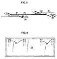
- the area of the openings 24 is substantially adapted to the excess air generated by the air jets 30 in that tunnel section length. Since the pressure in the tunnel 20 decreases from the end 28 towards the outlet opening 3, the area of the openings 24 should increase in the same direction, as shown in Fig. 6.
- the upper wall 21 of the tunnel 20 can be made up of a plurality of substantially rectangular metal sheets 31 overlapping in the longitudinal direction of the tunnel 20. Between the metal sheets 31 are mounted spacers 32 having a thickness of, for instance, no more than a few millimetres, the nozzles 22 being defined by two metal sheets 31 and two spacers 32, or one spacer 32 and one side wall 25.
- the front and rear edges of each sheet 31 are outwardly bent from the plane of the sheet to direct the air jets 30 obliquely forwards and downwards, towards the end 28 of the tunnel.
- the pressure in the chamber 26 should be many times higher than the pressure at the end 28 of the tunnel 20, i.e. the maximum pressure in the tunnel 20.
- the invention is not restricted to the embodiment described above. Naturally, it may also be used in air treatment plants for refrigerating, heating or drying. Further, the inventive tunnel may be arranged at both the outlet and the inlet opening, or at only one of these openings. Moreover, the air flow stopped by the tunnel may be directed towards or from the opening at issue.
Landscapes
- Engineering & Computer Science (AREA)
- Life Sciences & Earth Sciences (AREA)
- Chemical & Material Sciences (AREA)
- Wood Science & Technology (AREA)
- Zoology (AREA)
- Food Science & Technology (AREA)
- Polymers & Plastics (AREA)
- Mechanical Engineering (AREA)
- General Engineering & Computer Science (AREA)
- Physics & Mathematics (AREA)
- Combustion & Propulsion (AREA)
- Thermal Sciences (AREA)
- Freezing, Cooling And Drying Of Foods (AREA)
- Ventilation (AREA)
- Fertilizers (AREA)
- General Preparation And Processing Of Foods (AREA)
- Treating Waste Gases (AREA)
- Materials For Photolithography (AREA)
- Addition Polymer Or Copolymer, Post-Treatments, Or Chemical Modifications (AREA)
- Food Preservation Except Freezing, Refrigeration, And Drying (AREA)
Abstract
Description
- The present invention generally relates to air treatment plants for food; such plants usually comprise a housing, a conveyor adapted to feed food to be processed through an inlet opening in said housing, to and through an air treatment area, and to feed the processed food from said area to and through an outlet opening in said housing, a heat exchanger, and a circulation fan for generating a circulating air flow through the heat exchanger, the air treatment area, and the circulation fan in succession.
- More precisely, the invention concerns a method of conveyance through an inlet or outlet of an air treatment plant of this type. The invention is also directed at such a plant for carrying out the inventive method.
- It is the fan in such air treatment plants that generates the requisite pressure increase for propelling the air flow through the heat exchanger and the air treatment area. Thus, there occurs within this area a pressure drop in the direction of the air flow.
- Increasing the capacity of such an air treatment plant either requires an increased air flow, i.e. a higher air flow velocity, or an enlarged air treatment area. In both cases, the pressure drop within the air treatment area must be increased, thus augmenting the tendency to unwanted air flows through the inlet opening and/or the outlet opening of the housing.
- One object of the invention is, therefore, to provide a method for reducing such air flows, especially in an air treatment plant of the type stated in the introduction to this specification, in which the conveyor travels through an inlet tunnel communicating with the inlet opening and/or an outlet tunnel communicating with the outlet opening. Another object of the invention is to provide and air treatment plant of the type stated in the introduction to this specification, by which the inventive method can be implemented.
- WO90/15294 being a document according to Article 54(3) EPC, discloses an air treatment plant of the type stated in the introduction to this specification, wherein air curtain ducts are directed substantially transversely of a conveyor path and some of the circulating air flows through the ducts so as to reduce the air exchange between the interior and the exterior of the housing.
- According to the invention, a method of conveyance through an inlet our outlet of an air treatment plant has the features defined in
claim 1. - The air jets may be directed by nozzles distributed across the upper wall or upper boundary surface of the tunnel.
- Suitably, the evacuation openings are dimensioned so as to let through substantially the same amount of air as is supplied by the air jets. In each section of the tunnel length, the area of the openings should further be substantially adapted to the excess air in that tunnel section length.
- According to the invention, an air treatment plant for food has the features defined in claim 6.
- Suitably, the evacuation openings are dimensioned so as to let through substantially the same amount of air as is supplied by the air jets. Most preferably, the area of the openings in each section of the tunnel length is substantially adapted to the excess air in that tunnel section length.
- One embodiment of the invention will be described below, reference being had to the accompanying drawings, in which
- Figs 1 and 2 are schematic cross-sections of two prior art refrigerating plants to which the invention is applicable,
- Fig. 3 illustrates an embodiment of the invention applied to the refrigerating plant in Fig. 1,
- Fig. 4 is a plan view of an upper wall in Fig. 3,
- Fig. 5 is a longitudinal section taken along the line V-V in Fig. 4, and
- Fig. 6 is a plan view of a lower wall in Fig. 3.
- The refrigerating plant shown in Fig. 1 comprises a
housing 1 with an inlet opening 2 and an outlet opening 3. The interior of thehousing 1 communicates with the surrounding atmosphere only via these openings 2 and 3. A conveyor consists of aconveyor belt 4 and a supporting structure (not shown). Theconveyor belt 4 travels through the inlet opening 2 to the centre of thehousing 1 where it takes a helical path up through saidhousing 1 which it leaves through the outlet opening 3. Theconveyor belt 4 is endless, and its return path from the outlet opening 3 to the inlet opening 2 on the outside of thehousing 1 is not shown. Owing to the helical path of the belt inside thehousing 1, a drum-shaped belt pile is formed, which has a central through opening and which, at its bottom, is closed by means of asheet metal plate 5. In addition, thehousing 1 contains a circulation fan 6, a cooling-coil battery 7, andpartitions coil battery 7, the belt pile and itself, as indicated by arrows. The belt pile, through which the circulating air flows, defines an air treatment area for the food carried on theconveyor belt 4. Thebottom plate 5 and thepartitions - In the refrigerating plant shown in Fig. 1, the pressure between the fan 6 and the cooling-
coil battery 7 is substantially higher than the ambient pressure, the pressure between the cooling-coil battery 7 and the belt pile is higher than the ambient pressure, and the pressure in the remainder of thehousing 1 just about equals the ambient pressure. - The embodiment shown in Fig. 2 of a prior art refrigerating plant corresponds to the embodiment in Fig. 1, with the exception of the provision of a
cover plate 5′ and the positions of thepartitions 9′ and 10′. Owing to these dissimilarities, the pressure between the fan 6 and the cooling-coil battery 7 is, in the embodiment of Fig. 2, higher than the ambient pressure, the pressure between the cooling-coil battery 7 and the belt pile is substantially equal to the ambient pressure, and the pressure between the belt pile and the fan 6 is lower than the ambient pressure. - In Fig. 3, which corresponds to the left upper part of the refrigerating plant in fig. 1, an
outlet tunnel 20 communicates with the outlet opening 3. Thetunnel 20 has an upper boundary surface in the form of anupper wall 21 provided with a plurality ofair supply nozzles 22, as well as a lower boundary surface in the form of alower wall 23 formed with a plurality ofopenings 24. Thetunnel 20 is further defined byside walls 25, one of which is shown in Fig. 3. - The
lower wall 23 is directly connected to thepartition 10. Theupper wall 21 constitutes the bottom of achamber 26 in which afan 27 generates a comparatively high pressure by sucking in air from the area on the high-pressure side of the belt pile formed of thebelt 4. - During operation of the refrigerating plant in Figs 1 and 3, the pressure at the
inner end 28 of thetunnel 20 becomes higher than the ambient pressure, thus tending to generate an air flow through thetunnel 20 in adirection 29, towards and through the outlet opening 3. This is, of course, highly undesirable, and is prevented altogether, or at least almost, by the fan-generated pressure in thechamber 26, producingstrong air jets 30 from thenozzles 22 substantially opposite to thedirection 29. When properly dimensioned, theseair jets 30 stop and prevent all air flow through thetunnel 20 from theend 28 to the outlet opening 3. - The
air jets 30, which all have essentially the same high initial velocity, will spend their energy fairly quickly, thereby producing an excess of air in thetunnel 20, which is evacuated through theopenings 24 in thelower wall 23 to the compartment below where there is essentially ambient pressure. - Thus, it is important that the
openings 24 are so dimensioned that they let through substantially the same volume of air as is supplied by theair jets 30. To avoid as far as possible the emergence of air flows in the longitudinal direction of thetunnel 20, it is further desirable that, in each section of the tunnel length, the area of theopenings 24 is substantially adapted to the excess air generated by theair jets 30 in that tunnel section length. Since the pressure in thetunnel 20 decreases from theend 28 towards the outlet opening 3, the area of theopenings 24 should increase in the same direction, as shown in Fig. 6. - As is apparent from Figs 4 and 5, the
upper wall 21 of thetunnel 20 can be made up of a plurality of substantiallyrectangular metal sheets 31 overlapping in the longitudinal direction of thetunnel 20. Between themetal sheets 31 are mountedspacers 32 having a thickness of, for instance, no more than a few millimetres, thenozzles 22 being defined by twometal sheets 31 and twospacers 32, or onespacer 32 and oneside wall 25. The front and rear edges of eachsheet 31 are outwardly bent from the plane of the sheet to direct theair jets 30 obliquely forwards and downwards, towards theend 28 of the tunnel. - To give the
air jets 30 the requisite velocity, the pressure in thechamber 26 should be many times higher than the pressure at theend 28 of thetunnel 20, i.e. the maximum pressure in thetunnel 20. - It goes without saying that the invention is not restricted to the embodiment described above. Naturally, it may also be used in air treatment plants for refrigerating, heating or drying. Further, the inventive tunnel may be arranged at both the outlet and the inlet opening, or at only one of these openings. Moreover, the air flow stopped by the tunnel may be directed towards or from the opening at issue.
Claims (9)
- A method of conveyance through an inlet or outlet of an air treatment plant (1) for food comprising an inlet our outlet tunnel (20) having an upper wall (21) and a lower wall (23) and communicating with an inlet our outlet opening (2,3) of the plant which is otherwise closed and in which air is circulated by increased air pressure thereby causing a tendency of the circulating air to flow in one direction (29) in the tunnel (20), the method comprising feeding food through the inlet opening (2) or tunnel (20) to an air treatment area within the plant, feeding the treated food through the outlet opening (3) or tunnel (20), and directing a plurality of air jets (30) from the upper wall (21) substantially opposite to said one direction (29) and evacuating the excess air produced by the air jets (30) from the tunnel through openings (24) in the lower wall (23), whereby the air flow in said one direction (29) in the tunnel (20) is reduced.
- The method of claim 1, characterised in that the air jets (30) are directed by nozzles (22) distributed across the upper boundary surface (21) of the tunnel (20).
- The method of claim 1 or 2, characterised in that the evacuation openings (24) are dimensioned so as to let through substantially the same amount of air as is supplied by the air jets (30).
- The method of claim 3, characterised in that, in each section of the tunnel length, the area of the openings (24) is substantially adapted to the excess air generated by the air jets (30) in that tunnel section length.
- The method of any one of claims 1-4, characterised in that substantially the same initial velocity is imparted to all the air jets (30).
- An air treatment plant (1) for food comprising an inlet our outlet tunnel (20) having an upper wall (21) and a lower wall (23) and communicating with an inlet or outlet opening (2,3) of the plant which is otherwise closed, an air treatment area whitin the plant (1), means (4) for feeding food through the inlet opening (2) or tunnel (20) to the air treatment area and feeding treated food from the air treatment area through the outlet opening (3) or tunnel (20), means (6) for circulating the treatment air by producing a pressure increase, thereby causing a tendency of the treatment air to flow in one direction (29) through the inlet or outlet tunnel (20), a fan (27), nozzles (22) arranged in the upper wall (21) and connected to the fan (27) so as to produce air jets (30) directed substantially opposite to said one direction (29), and openings (24) in the lower wall (23) for evacuating the excess air in the tunnel (20) produced by the air jets (30).
- The air treatment plant of claim 6, characterised in that, in each section of the tunnel length, the area of the openings (24) is adapted to let through the excess air in that tunnel section length.
- The air treatment plant of claim 7, characterised in that the area of the openings (24) increases in said direction (29).
- The air treatment plant of any one of claims 6-8, characterised in that the upper wall (21) is made up of a plurality of metal sheets (31) overlapping in the longitudinal direction of the tunnel (20) and having intermediate spacers (32) for forming nozzles (22) distributed across the entire with and entire length of the upper wall (21).
Applications Claiming Priority (3)
| Application Number | Priority Date | Filing Date | Title |
|---|---|---|---|
| SE8904056 | 1989-11-29 | ||
| SE8904056A SE464779B (en) | 1989-11-29 | 1989-11-29 | AIR TREATMENT PLANT AND PROCEDURES FOR AIR FLOW REDUCTION IN A SUCH |
| PCT/SE1990/000781 WO1991008430A1 (en) | 1989-11-29 | 1990-11-28 | Air treatment plant and method for a flow reduction therein |
Publications (2)
| Publication Number | Publication Date |
|---|---|
| EP0502948A1 EP0502948A1 (en) | 1992-09-16 |
| EP0502948B1 true EP0502948B1 (en) | 1994-09-28 |
Family
ID=20377657
Family Applications (1)
| Application Number | Title | Priority Date | Filing Date |
|---|---|---|---|
| EP91900415A Expired - Lifetime EP0502948B1 (en) | 1989-11-29 | 1990-11-28 | Air treatment plant and method for a flow reduction therein |
Country Status (10)
| Country | Link |
|---|---|
| US (1) | US5247801A (en) |
| EP (1) | EP0502948B1 (en) |
| JP (1) | JP2728314B2 (en) |
| AU (1) | AU639795B2 (en) |
| CA (1) | CA2069871C (en) |
| DE (1) | DE69013006T2 (en) |
| ES (1) | ES2061225T3 (en) |
| RU (1) | RU2082066C1 (en) |
| SE (1) | SE464779B (en) |
| WO (1) | WO1991008430A1 (en) |
Families Citing this family (10)
| Publication number | Priority date | Publication date | Assignee | Title |
|---|---|---|---|---|
| SE506231C2 (en) * | 1995-04-05 | 1997-11-24 | Frigoscandia Equipment Ab | Methods and apparatus for air treatment of products |
| BE1009377A3 (en) * | 1995-05-09 | 1997-03-04 | Consejo Superior Investigacion | Method and drying device. |
| ES2161568B1 (en) * | 1996-03-29 | 2004-06-16 | PABLO SOCIEDAD AGRARIA DE TRANSFORMACION (S.A.T.) "SAN CAYETANO" | ALPI FAST COOLING SYSTEM FOR FRUITS, WHOLE VEGETABLES OR PARTS AND OTHER PRODUCTS. |
| JP3184775B2 (en) * | 1997-02-20 | 2001-07-09 | 大宇電子株式會▲社▼ | Refrigerator with a function of discharging cool air from doors using an air curtain generator |
| ES2163341B1 (en) * | 1998-07-13 | 2002-12-01 | Tecn Frigorificas Hermanos Cat | PRE-COOLING AND HEATING SYSTEM OF PRODUCTS BY AIR DEPRESSION. |
| US6263680B1 (en) * | 2000-01-18 | 2001-07-24 | The Boc Group, Inc. | Modular apparatus for cooling and freezing of food product on a moving substrate |
| JP5586862B2 (en) * | 2009-03-03 | 2014-09-10 | 延幸 高橋 | Heat treatment method, heat treatment apparatus, heat treatment system, and set for treatment method |
| JP5586871B2 (en) * | 2009-05-01 | 2014-09-10 | 延幸 高橋 | Heat treatment method, heat treatment apparatus, heat treatment system, and set for treatment method |
| JP7018282B2 (en) * | 2017-09-28 | 2022-02-10 | 株式会社前川製作所 | Spiral conveyor type freezer device |
| US11485581B2 (en) | 2019-10-29 | 2022-11-01 | John Bean Technologies Ab | Air balance tunnel for spiral conveyor |
Family Cites Families (10)
| Publication number | Priority date | Publication date | Assignee | Title |
|---|---|---|---|---|
| US3238736A (en) * | 1963-05-16 | 1966-03-08 | Elmwood Liquid Products Inc | Liquid nitrogen freezing system |
| US3267585A (en) * | 1965-03-03 | 1966-08-23 | Rudolph E Futer | Changing the temperatures of objects by gas jets |
| US3600901A (en) * | 1969-03-17 | 1971-08-24 | Integral Process Syst Inc | Gas balance control in flash freezing systems |
| CH518510A (en) * | 1970-01-14 | 1972-01-31 | Buehler Ag Geb | Device for the continuous thermal treatment of granular material by means of a gas |
| US3789516A (en) * | 1971-10-08 | 1974-02-05 | Werner & Pfleiderer | Continuous tunnel oven for baking and/or drying |
| US3855815A (en) * | 1972-06-19 | 1974-12-24 | Hollymatic Corp | Refrigerating apparatus |
| US3824806A (en) * | 1972-06-19 | 1974-07-23 | Integral Process Syst Inc | Apparatus for refrigerating articles |
| US4100760A (en) * | 1973-07-30 | 1978-07-18 | Cheney Paul L | Fluid suspension freezer and method |
| US4177647A (en) * | 1977-10-06 | 1979-12-11 | Lewis Refrigeration Co. | Air slide freezer system |
| US4813245A (en) * | 1988-01-13 | 1989-03-21 | Liquid Air Corporation | High efficiency linear freezer |
-
1989
- 1989-11-29 SE SE8904056A patent/SE464779B/en not_active IP Right Cessation
-
1990
- 1990-11-28 JP JP3500720A patent/JP2728314B2/en not_active Expired - Fee Related
- 1990-11-28 ES ES91900415T patent/ES2061225T3/en not_active Expired - Lifetime
- 1990-11-28 DE DE69013006T patent/DE69013006T2/en not_active Expired - Fee Related
- 1990-11-28 RU SU5052134/06A patent/RU2082066C1/en not_active IP Right Cessation
- 1990-11-28 WO PCT/SE1990/000781 patent/WO1991008430A1/en not_active Ceased
- 1990-11-28 AU AU78971/91A patent/AU639795B2/en not_active Ceased
- 1990-11-28 EP EP91900415A patent/EP0502948B1/en not_active Expired - Lifetime
- 1990-11-28 CA CA002069871A patent/CA2069871C/en not_active Expired - Lifetime
-
1992
- 1992-06-09 US US07/854,599 patent/US5247801A/en not_active Expired - Lifetime
Non-Patent Citations (1)
| Title |
|---|
| WO 90/15294 * |
Also Published As
| Publication number | Publication date |
|---|---|
| EP0502948A1 (en) | 1992-09-16 |
| DE69013006T2 (en) | 1995-02-02 |
| SE464779B (en) | 1991-06-10 |
| CA2069871C (en) | 2000-02-08 |
| JPH05504824A (en) | 1993-07-22 |
| CA2069871A1 (en) | 1991-05-30 |
| AU639795B2 (en) | 1993-08-05 |
| WO1991008430A1 (en) | 1991-06-13 |
| SE8904056D0 (en) | 1989-11-29 |
| ES2061225T3 (en) | 1994-12-01 |
| JP2728314B2 (en) | 1998-03-18 |
| DE69013006D1 (en) | 1994-11-03 |
| AU7897191A (en) | 1991-06-26 |
| US5247801A (en) | 1993-09-28 |
| RU2082066C1 (en) | 1997-06-20 |
Similar Documents
| Publication | Publication Date | Title |
|---|---|---|
| US6760981B2 (en) | Compact convection drying chamber for drying printed circuit boards and other electronic assemblies by enhanced evaporation | |
| US5247801A (en) | Air treatment plant and method for a flow reduction therein | |
| US4474498A (en) | Multiple-pass impingement heating and cooling device | |
| EP0676028B1 (en) | Apparatus for gas treatment of products | |
| US4354549A (en) | Induced circulation oven or cooler | |
| US5702245A (en) | Conveyor for processing equipment having gas flow compensation | |
| US4467537A (en) | Equipment for heat-treating flat, band-like lengths of material | |
| US2984085A (en) | Walk-in cooler apparatus | |
| USRE42510E1 (en) | Apparatus for gas treatment of products | |
| US4298341A (en) | Industrial oven having air recirculating means for minimizing heat loss | |
| RU95113412A (en) | DEVICE FOR GAS PROCESSING OF PRODUCTS | |
| JP2000513055A (en) | Flotation dryer unit | |
| US4972681A (en) | Freezing device | |
| US5396716A (en) | Jet tube dryer with independently controllable modules | |
| EP0474755B1 (en) | Air treatment plant and method for reducing the air exchange between the ambient atmosphere and the inside of the plant | |
| US5253569A (en) | Serpentine food processing with closed-loop recirculation | |
| JPH08247648A (en) | Drying system for dried objects | |
| US3140929A (en) | Cooling device for dried wall-board sheets | |
| EP1926385B1 (en) | Device for treating elongate food products with a conditioned airflow | |
| EP0377311A1 (en) | Forced circulation airing nozzle box construction | |
| US3006080A (en) | Convection treatment apparatus | |
| HU200663B (en) | Steam-operation precooling apparatus for servicing preserves-industrial production lines serving particularly for processing fruits and vegetables | |
| JPH09154554A (en) | Food freezing equipment | |
| MXPA01007346A (en) | Apparatus for gas treatment of products |
Legal Events
| Date | Code | Title | Description |
|---|---|---|---|
| PUAI | Public reference made under article 153(3) epc to a published international application that has entered the european phase |
Free format text: ORIGINAL CODE: 0009012 |
|
| 17P | Request for examination filed |
Effective date: 19920521 |
|
| AK | Designated contracting states |
Kind code of ref document: A1 Designated state(s): DE DK ES FR GB IT NL |
|
| 17Q | First examination report despatched |
Effective date: 19930510 |
|
| GRAA | (expected) grant |
Free format text: ORIGINAL CODE: 0009210 |
|
| AK | Designated contracting states |
Kind code of ref document: B1 Designated state(s): DE DK ES FR GB IT NL |
|
| PG25 | Lapsed in a contracting state [announced via postgrant information from national office to epo] |
Ref country code: DK Effective date: 19940928 |
|
| ITF | It: translation for a ep patent filed | ||
| REF | Corresponds to: |
Ref document number: 69013006 Country of ref document: DE Date of ref document: 19941103 |
|
| REG | Reference to a national code |
Ref country code: ES Ref legal event code: FG2A Ref document number: 2061225 Country of ref document: ES Kind code of ref document: T3 |
|
| ET | Fr: translation filed | ||
| PLBE | No opposition filed within time limit |
Free format text: ORIGINAL CODE: 0009261 |
|
| STAA | Information on the status of an ep patent application or granted ep patent |
Free format text: STATUS: NO OPPOSITION FILED WITHIN TIME LIMIT |
|
| 26N | No opposition filed | ||
| REG | Reference to a national code |
Ref country code: GB Ref legal event code: IF02 |
|
| PGFP | Annual fee paid to national office [announced via postgrant information from national office to epo] |
Ref country code: NL Payment date: 20051005 Year of fee payment: 16 |
|
| PGFP | Annual fee paid to national office [announced via postgrant information from national office to epo] |
Ref country code: ES Payment date: 20051123 Year of fee payment: 16 |
|
| PG25 | Lapsed in a contracting state [announced via postgrant information from national office to epo] |
Ref country code: NL Free format text: LAPSE BECAUSE OF NON-PAYMENT OF DUE FEES Effective date: 20070601 |
|
| NLV4 | Nl: lapsed or anulled due to non-payment of the annual fee |
Effective date: 20070601 |
|
| REG | Reference to a national code |
Ref country code: ES Ref legal event code: FD2A Effective date: 20061129 |
|
| PG25 | Lapsed in a contracting state [announced via postgrant information from national office to epo] |
Ref country code: ES Free format text: LAPSE BECAUSE OF NON-PAYMENT OF DUE FEES Effective date: 20061129 |
|
| PGFP | Annual fee paid to national office [announced via postgrant information from national office to epo] |
Ref country code: IT Payment date: 20081127 Year of fee payment: 19 |
|
| PGFP | Annual fee paid to national office [announced via postgrant information from national office to epo] |
Ref country code: FR Payment date: 20071130 Year of fee payment: 18 Ref country code: DE Payment date: 20081223 Year of fee payment: 19 |
|
| PGFP | Annual fee paid to national office [announced via postgrant information from national office to epo] |
Ref country code: GB Payment date: 20081128 Year of fee payment: 19 |
|
| REG | Reference to a national code |
Ref country code: FR Ref legal event code: ST Effective date: 20090731 |
|
| GBPC | Gb: european patent ceased through non-payment of renewal fee |
Effective date: 20091128 |
|
| PG25 | Lapsed in a contracting state [announced via postgrant information from national office to epo] |
Ref country code: DE Free format text: LAPSE BECAUSE OF NON-PAYMENT OF DUE FEES Effective date: 20100601 |
|
| PG25 | Lapsed in a contracting state [announced via postgrant information from national office to epo] |
Ref country code: GB Free format text: LAPSE BECAUSE OF NON-PAYMENT OF DUE FEES Effective date: 20091128 |
|
| PG25 | Lapsed in a contracting state [announced via postgrant information from national office to epo] |
Ref country code: IT Free format text: LAPSE BECAUSE OF NON-PAYMENT OF DUE FEES Effective date: 20091128 |
|
| PG25 | Lapsed in a contracting state [announced via postgrant information from national office to epo] |
Ref country code: FR Free format text: LAPSE BECAUSE OF NON-PAYMENT OF DUE FEES Effective date: 20081130 |