EP0502811A2 - Mesure du poids d'un hélicoptère - Google Patents
Mesure du poids d'un hélicoptère Download PDFInfo
- Publication number
- EP0502811A2 EP0502811A2 EP92630026A EP92630026A EP0502811A2 EP 0502811 A2 EP0502811 A2 EP 0502811A2 EP 92630026 A EP92630026 A EP 92630026A EP 92630026 A EP92630026 A EP 92630026A EP 0502811 A2 EP0502811 A2 EP 0502811A2
- Authority
- EP
- European Patent Office
- Prior art keywords
- weight
- signal
- corrected
- measuring
- airspeed
- Prior art date
- Legal status (The legal status is an assumption and is not a legal conclusion. Google has not performed a legal analysis and makes no representation as to the accuracy of the status listed.)
- Granted
Links
Images
Classifications
-
- G—PHYSICS
- G01—MEASURING; TESTING
- G01G—WEIGHING
- G01G19/00—Weighing apparatus or methods adapted for special purposes not provided for in the preceding groups
- G01G19/02—Weighing apparatus or methods adapted for special purposes not provided for in the preceding groups for weighing wheeled or rolling bodies, e.g. vehicles
- G01G19/07—Weighing apparatus or methods adapted for special purposes not provided for in the preceding groups for weighing wheeled or rolling bodies, e.g. vehicles for weighing aircraft
Definitions
- This invention relates to weight measurement and more particularly to measuring the weight of a helicopter while in flight.
- weight of an aircraft on the ground can be measured by various means.
- the weight of a fixed wing aircraft is typically measured on the ground by weight scales or by a weight on wheels (WOW) device, or in the case of a helicopter, weight is typically determined by manually tracking fuel, cargo, and passenger weight.
- WOW weight on wheels
- the ability to sustain a hover varies as a function of flight parameters such as air density, temperature, and vehicle weight. For example, at a given altitude, temperature, and gross weight, the helicopter may have no difficulty sustaining a hover. However, if the altitude or temperature increases, the air density will decrease and a hover may not be sustainable at the new condition. Therefore, accurate weight measurement during flight also allows a wider range of mission profiles, passenger or equipment deployment, and hover maneuvers within the permissible flight envelope.
- Objects of the invention include provision of weight measurement in a helicopter which provides vehicle weight continuously during flight and is unaffected by altitude, temperature, or other aerodynamic load changes but reacts dynamically to physical load changes as helicopter weight varies.
- the gross weight of a helicopter is determined by measuring distances from known points on the vehicle fuselage to the underside of the rotor blades, and calculating the gross vehicle weight from these distances and other flight information.
- the invention avoids requiring the flight crew to monitor and track weight changes and performs this function more accurately and efficiently. Furthermore, the invention represents a significant improvement over previous methods of determining vehicle weight by providing accurate weight measurement continuously during flight and reacting immediately to on-loading or off-loading weight.
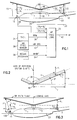
- Fig. 1 is a schematic block diagram of a helicopter weight measurement system of the invention employing distance measuring devices.
- Fig. 2 is a free body diagram showing the balance of forces on a rotor blade.
- Fig. 3 is a side view of a helicopter showing an alternative mounting configuration for the distance sensors used in accordance with the present invention.
- a helicopter weight measurement system includes at least two distance measuring devices 10,12 located known distances r1,r2 from the main rotor shaft 18, which measure the vertical distances 20,22 perpendicular to the vehicle centerline 23 from known points on the fuselage 24 to the underside of a plurality of rotating main rotor blades 26.
- the distance measuring devices may be any known device capable of measuring the distance from one object to another that does not require physical touching, e.g. a laser diode device such as a Mitsubishi Laser Diode, Model No. ML3101.
- a laser diode device transmits a beam of coherent light and detects light of the same type which is reflected back (also known as optical backscatter).
- the sensors should be able to detect a low level of returning light to allow for light absorption by the rotor blades, which are typically composed of fiberglass or aluminum and covered with an epoxy paint exhibiting a dull finish.
- the distance sensors provide analog electrical signals proportional to the distance measured, i.e., when a blade is directly above the sensor the output voltage will be proportional to the distance to the blade and when there is no blade over the sensor (no reflection) the output will be zero volts.
- the distance sensors 10,12 provide distance signals continuously on two lines 28,30, respectively, to weight calculation logic 32.
- the electrical signals provided by the sensors may be amplified to increase signal strength and filtered to remove signal noise prior to being coupled to the output lines 28,30.
- the weight calculation logic 32 consists of a peak detector for each distance sensor (i.e., a known circuit which charges to and holds the largest voltage that it sees) responsive to the analog distance signal, and an analog to digital converter (A/D), responsive to the peak detectors, which converts the peak voltages to digital bits representing the distances measured.
- A/D analog to digital converter
- the peak detector is reset to allow the next peak voltage to be measured and held.
- the A/D sample rate for each sensor is set faster than the maximum rotor speed multiplied by the number of blades.
- a rotor speed signal is provided by a known tachometer 34, which provides an analog voltage proportional to main rotor speed, to the weight calculation logic on a line 36.
- an airspeed sensor 38 e.g. a pitostatic sensor that determines airspeed from static pressure and total ram pressure created by forward velocity, provides an analog voltage signal proportional to the forward airspeed of the vehicle on a line 40 to the weight calculation logic 32.
- An analog multiplexer may be employed within the weight calculation logic 32 to switch between analog input signals.
- the logic 32 also contains known signal processing components capable of performing mathematical operations (e.g., digital adders, multipliers, and table look-ups), responsive to the digital bits from the A/D converter.
- the output of the weight calculation logic provides a signal on a line 42 indicative of gross vehicle weight corrected for non-ideal (real-world) helicopter effects.
- Blade track is the term used to describe how well the tip paths of the rotor blades track each other and is a function of the individual blade pitch. It is known that if two blades do not track each other, the vertical lift force produced by one blade will be different from that of the other. Consequently, the distance from the fuselage to the blades may vary from one blade to the next, giving varying distance sensor readings. To eliminate such variation, the distances are continuously sampled and averaged by the weight calculation logic 32 using known signal processing hardware, over a period of time, e.g., 5 seconds.
- the two sensors 10,12 are mounted known distances d1,d3 below the point of rotation of the rotor blades 46 (i.e., the point where the rotor blades are connected to the rotor shaft, also known as the rotor head).
- the distances d1,d3 are subtracted from the distances 20,22 measured by the respective sensor, yielding the distances d2,d4.
- the distances d2,d4 are averaged to cancel the effects of vehicle pitch and rotor tilt (e.g., occurring in forward flight). If the horizontal distances r1,r2 from the two sensors to the main rotor shaft 18 are not identical, a common horizontal distance must be selected and the vertical distances scaled to that point before the two vertical distances d2,d4 are averaged.
- the angle formed relative to the horizontal, by the rotor blades in rotation as seen when the helicopter is viewed from the side, is related to the weight of the helicopter.
- This angle is also known as the "coning angle" 52.
- the coning angle 52 changes by only approximately 6 degrees from flat pitch to the pitch associated with lifting the maximum gross weight of the vehicle. Therefore, a device which measures the angle directly would be prone to inaccuracies due to insufficient resolution.
- the invention measures the vertical distances from two points located on the vehicle fuselage, one being forward of the rotor shaft and the other being aft of the shaft, to the rotor blades. More than two points may be used if desired, however, information regarding vehicle roll may also be required if more than two points are utilized.
- the points chosen on the fuselage should be as close as possible to the end (tip) of the blade to maximize sensitivity and accuracy of the weight calculation.
- n the number of blades
- L the aerodynamic lift produced by one blade
- F the force exerted by the centripetal acceleration of a blade in rotation (i.e., centripetal or radial force)
- d the corrected averaged vertical distance from the rotor hub to the underside of the spinning main rotor blades
- r the horizontal distance from aforementioned common measurement point on the fuselage to the main rotor shaft.
- the weight of each blade is assumed to be evenly distributed along its length, and the blade is assumed to be infinitely stiff. Therefore, a coning angle of approximately zero degrees exists when there is no weight suspended from the rotor hub.
- the weight obtained from eq. 3 is the weight of an ideal helicopter having no correction for non-ideal effects such as horizontal or vertical drag, or uneven blade weight distribution.
- the weight calculation logic of Fig. 1 uses eqs. 3 and 4 together with the measured rotor speed signal on the line 36 to calculate the ideal weight of the helicopter.
- a vehicle To correct for vertical drag effects, a vehicle must first be calibrated to determine its vertical drag characteristics. Each different vehicle type having a unique fuselage and blade design must be calibrated. However, a vehicle need not be recalibrated unless a change is made that affects the vertical drag, e.g., a change in the rotor blades, or a change in the size or shape of the fuselage or attachments thereto.
- Calibration of the vertical drag force is performed, using known techniques, by plotting the actual weight of the vehicle against the ideal weight calculated by eqs. 3 and 4 at various different rotor speeds (e.g., 95%, 100%, and 105%), and at various different vehicle weights (e.g., 6,000 to 10,000 lbs in increments of 500 lbs) induced by lifting against a short cable with a load cell (i.e., a device capable of measuring cable tension) attached to an anchor point ("dead man") on the ground.
- a load cell i.e., a device capable of measuring cable tension
- Different values or more values of rotor speed and vehicle weight may be used if desired.
- the weight calculation logic 32 calculates the ideal weight by eqs. 3 and 4 and corrects the ideal weight for vertical drag using the measured rotor speed signal on the line 36, and a bivariate (two inputs one output) table look-up derived from the aforementioned vertical drag calibration of the vehicle.
- the inputs to the table are rotor speed, and the ideal weight calculated from eqs. 3 and 4.
- the output of the table, actual vehicle weight corrected for vertical drag, is linearly interpolated by known means (e.g., two dimensional linear regression) from the two input points.
- the horizontal drag force is a force exerted by the air on the front surface area of the fuselage when the vehicle is in forward horizontal flight that requires the rotor to produce more rotor thrust to achieve the same speed than would be required given no horizontal drag, thereby affecting the coning angle.
- Calibration of horizontal drag is performed, as is known, in level unaccelerated forward flight.
- the aircraft is weighed prior to calibration and adjusted by flight test instrumentation for fuel consumption during the test.
- Calibration is performed by plotting the actual weight of the vehicle against the ideal weight calculated by eqs. 3 and 4 at various different rotor speeds (e.g., 95%, 100%, and 105%), at various different vehicle weights (e.g., three different weights from 6,000 to 10,000 lbs) induced by placing weights in the vehicle, and at various different forward airspeeds (e.g., 60, 80, 100, 120, 140, and 150 knots). Different values or more values of rotor speed, vehicle weight, and airspeed may be used if desired.
- the ideal weight calculated by eqs. 3 and 4 is corrected for horizontal drag by the weight calculation logic 32 of Fig. 1 using the measured rotor speed signal on the line 36, forward airspeed on the line 40, and a the trivariate (three inputs one output) table look-up derived from the aforementioned horizontal drag calibration of the vehicle.
- the inputs to the table are rotor speed, forward airspeed, and the ideal weight calculated by eqs. 3 and 4.
- the output of the table, actual vehicle weight corrected for horizontal drag is linearly interpolated by known means (e.g. three dimensional linear regression) from the three input points.
- the corrections for horizontal and vertical drag are mutually exclusive.
- the weight calculation logic selects between the two corrections based on the airspeed signal on the line 40. When the airspeed signal indicates an airspeed less than 40 knots, the weight calculation logic 32 will correct solely for vertical drag, and when the airspeed is greater than or equal to 40 knots, the logic will correct solely for horizontal drag. Correction of vertical and horizontal drag by the weight calculation logic may also be implemented using mathematical equations which are curve fit to the calibration data, instead of table look-ups.
- An inhibit signal on a line 54 may also be input to the weight calculation logic 32 of Fig. 1.
- the inhibit signal may come from any device which is capable of determining when the vehicle is not in level flight or hover, e.g., "Regime Recognition" logic 56 described in U.S. Pat. No. 4,933,882. However, this input is not required to calculate weight.
- the inhibit signal is used to inhibit (i.e. disable) the weight calculation logic from calculating vehicle weight when the flight conditions would render the weight calculation inaccurate, e.g., flight conditions other than hover and forward level flight.
- a downstream system receiving the weight signal may also monitor flight conditions and ignore the weight signal from the weight calculation logic when appropriate, thereby allowing the weight calculation logic to calculate weight continuously and eliminating the need for the inhibit signal as an input to the logic 32.
- Fig. 1 Although the invention is illustrated in Fig. 1 as being implemented with the distance sensors mounted to measure the distance perpendicular to the vehicle centerline 23, the invention will work equally as well with one or more sensors mounted at known angles ( ⁇ ) to the vehicle centerline 23 as illustrated in Fig. 3.
- the mounting angle ⁇ must be set to a value large enough to allow the laser light from the sensor to strike each passing rotor blade at all expected coning angles. Mounting the sensor at an angle has the advantage of allowing the sensors to measure closer to the tip of the blade. Additionally, sensor mounting angles may be chosen to measure points on the blades that are the same horizontal distance to the rotor shaft for both sensors. This eliminates the need for horizontal distance correction (shown in eq. 1) prior to averaging the two vertical distances. One or both sensors may be mounted at known angles if desired.
- the invention will work equally as well with other known distance measuring devices employing photoelectric, ultrasonic, or infrared technology.
- the composition or surface paint of the blades must be tailored to match the backscatter requirements for the type of sensing device used.
- the invention has been illustrated as being implemented using a helicopter with a single lifting rotor, the invention will work equally as well with a helicopter employing a plurality of lifting rotors, with each rotor having a set of distance sensors for weight measurement.
- the invention may be used on any aircraft employing a plurality of articulated (free to flap up and down) main lifting rotor blades, e.g., a gyroplane, comprising a horizontal thrust device and a free spinning rotor in autorotation, such as the Fairey Aviation "Rotodyne".
Landscapes
- Engineering & Computer Science (AREA)
- Aviation & Aerospace Engineering (AREA)
- Physics & Mathematics (AREA)
- General Physics & Mathematics (AREA)
- Navigation (AREA)
- Measurement Of Distances Traversed On The Ground (AREA)
- Toys (AREA)
- Control Of Position, Course, Altitude, Or Attitude Of Moving Bodies (AREA)
Applications Claiming Priority (2)
| Application Number | Priority Date | Filing Date | Title |
|---|---|---|---|
| US07/665,061 US5229956A (en) | 1991-03-06 | 1991-03-06 | Helicopter weight measurement |
| US665061 | 1991-03-06 |
Publications (3)
| Publication Number | Publication Date |
|---|---|
| EP0502811A2 true EP0502811A2 (fr) | 1992-09-09 |
| EP0502811A3 EP0502811A3 (en) | 1993-01-20 |
| EP0502811B1 EP0502811B1 (fr) | 1996-05-22 |
Family
ID=24668553
Family Applications (1)
| Application Number | Title | Priority Date | Filing Date |
|---|---|---|---|
| EP92630026A Expired - Lifetime EP0502811B1 (fr) | 1991-03-06 | 1992-03-05 | Mesure du poids d'un hélicoptère |
Country Status (5)
| Country | Link |
|---|---|
| US (1) | US5229956A (fr) |
| EP (1) | EP0502811B1 (fr) |
| JP (1) | JP3299561B2 (fr) |
| CA (1) | CA2061528A1 (fr) |
| DE (2) | DE69210872T2 (fr) |
Cited By (5)
| Publication number | Priority date | Publication date | Assignee | Title |
|---|---|---|---|---|
| RU2157977C2 (ru) * | 1998-02-12 | 2000-10-20 | Открытое акционерное общество Казанское научно-производственное предприятие "Вертолеты-МИ" | Способ измерения свободной тяги несущего винта вертолета на режиме висения |
| EP3098579A1 (fr) | 2015-05-29 | 2016-11-30 | Airbus Helicopters | Procede d'estimation de la masse instantanee d'un aeronef a voilure tournante |
| EP3122626A4 (fr) * | 2014-03-26 | 2017-12-06 | Sikorsky Aircraft Corporation | Estimation du poids brut et du centre de gravité |
| EP3521177A1 (fr) * | 2018-01-31 | 2019-08-07 | The Boeing Company | Dispositif d'estimation d'informations d'aéronefs |
| WO2022034001A1 (fr) * | 2020-08-14 | 2022-02-17 | Volkswagen Aktiengesellschaft | Procédé pour faire fonctionner un aéronef décollant et atterrissant verticalement et aéronef décollant et atterrissant verticalement |
Families Citing this family (19)
| Publication number | Priority date | Publication date | Assignee | Title |
|---|---|---|---|---|
| US5874673A (en) * | 1997-04-11 | 1999-02-23 | Safe Flight Instrument Corporation | Air speed and direction indicating system for rotary winged aircraft |
| US5987397A (en) * | 1998-03-13 | 1999-11-16 | The United States Of America As Represented By The Secretary Of The Navy | Neural network system for estimation of helicopter gross weight and center of gravity location |
| FR2784457B1 (fr) * | 1998-10-13 | 2001-01-05 | Sextant Avionique | Instruments combines de secours pour aeronef |
| RU2196305C2 (ru) * | 2001-01-29 | 2003-01-10 | Открытое акционерное общество "Казанское научно-производственное предприятие "Вертолеты-МИ" | Устройство для определения массы вертолета в горизонтальном полете |
| US7546975B2 (en) * | 2004-09-14 | 2009-06-16 | The Boeing Company | Tandem rotor wing rotational position control system |
| US7324016B1 (en) * | 2005-11-22 | 2008-01-29 | The United States Of America As Represented By The Secretary Of The Navy | Navigational indicating system for rotary wing aircraft |
| US7984146B2 (en) * | 2006-05-04 | 2011-07-19 | Sikorsky Aircraft Corporation | Aircraft health and usage monitoring system with comparative fleet statistics |
| US7857260B2 (en) * | 2007-01-19 | 2010-12-28 | Sikorsky Aircraft Corporation | Fuel jettison system |
| US20090083050A1 (en) * | 2007-09-25 | 2009-03-26 | Eltman Joseph T | Compilation and distribution of data for aircraft fleet management |
| US7983809B2 (en) * | 2007-12-21 | 2011-07-19 | Sikorsky Aircraft Corporation | Aircraft integrated support system (ISS) |
| EP2461142B1 (fr) * | 2010-12-01 | 2015-08-19 | AGUSTAWESTLAND S.p.A. | Procédé de calcul du poids de décollage d'un avion et système associé |
| EP2789536B1 (fr) | 2011-04-07 | 2016-12-07 | LORD Corporation | Dispositif à fluide de commande de mouvement instrumenté pour commander le mouvement de voilure tournante d'un aéronef |
| US9139290B2 (en) | 2013-09-10 | 2015-09-22 | Sikorsky Aircraft Corporation | Aircraft weight identification using filtered trim estimation |
| WO2016011099A1 (fr) | 2014-07-18 | 2016-01-21 | Sikorsky Aircraft Corporation | Système pour déterminer un poids sur roues à l'aide d'un lidar |
| CN104097790B (zh) * | 2014-07-28 | 2016-02-03 | 贵州航天风华精密设备有限公司 | 一种航天器操纵机构调试方法 |
| FR3068004B1 (fr) * | 2017-06-26 | 2019-07-19 | Airbus Helicopters | Train d'atterrissage muni d'un dispositif embarque de mesure de charge pour un aeronef et aeronef |
| CN112180980B (zh) * | 2020-10-16 | 2022-10-28 | 中国直升机设计研究所 | 一种无人直升机自转着陆控制方法 |
| CN114787036A (zh) * | 2020-12-21 | 2022-07-22 | 深圳市大疆创新科技有限公司 | 无人机机臂状态的检测方法、无人机的控制装置及无人机 |
| CN115014489B (zh) * | 2022-05-18 | 2024-03-19 | 杭州沛澜航空科技有限公司 | 无人直升机飞行重量测量方法及装置 |
Family Cites Families (12)
| Publication number | Priority date | Publication date | Assignee | Title |
|---|---|---|---|---|
| US3754440A (en) * | 1972-08-16 | 1973-08-28 | Us Navy | Helicopter lift margin determining system |
| US4034605A (en) | 1975-09-26 | 1977-07-12 | Pacer Systems Inc. | Maneuver margin presenting |
| US4143364A (en) * | 1976-08-19 | 1979-03-06 | Pitney-Bowes, Inc. | Optical displacement measuring system |
| US4300200A (en) * | 1978-12-01 | 1981-11-10 | Westland Aircraft Limited | Helicopter airspeed indicating system |
| US4312042A (en) * | 1979-12-12 | 1982-01-19 | Sundstrand Data Control, Inc. | Weight, balance, and tire pressure detection systems |
| US4574360A (en) * | 1983-04-01 | 1986-03-04 | Sundstrand Data Control, Inc. | Helicopter weight measuring system |
| SE457807B (sv) * | 1984-09-17 | 1989-01-30 | Peter Arnberg | Foerfarande och anordning foer maetning av vaegbanors baerighet |
| US4780838A (en) * | 1985-01-03 | 1988-10-25 | The Boeing Company | Helicopter weight and torque advisory system |
| GB2169572B (en) * | 1985-01-03 | 1988-02-10 | Boeing Co | A helicopter weight and torque advisory system |
| DE3662181D1 (en) * | 1985-05-16 | 1989-04-06 | Stewart Hughes Ltd | Improvements in and relating to tracker systems |
| CH671555A5 (fr) * | 1986-09-10 | 1989-09-15 | Zermatt Air Ag | |
| US4894787A (en) * | 1988-04-28 | 1990-01-16 | Kaman Aerospace Corporation | Automatic load monitoring system with remote sensing |
-
1991
- 1991-03-06 US US07/665,061 patent/US5229956A/en not_active Expired - Lifetime
-
1992
- 1992-02-19 CA CA002061528A patent/CA2061528A1/fr not_active Abandoned
- 1992-03-05 EP EP92630026A patent/EP0502811B1/fr not_active Expired - Lifetime
- 1992-03-05 DE DE69210872T patent/DE69210872T2/de not_active Expired - Fee Related
- 1992-03-05 JP JP08343192A patent/JP3299561B2/ja not_active Expired - Fee Related
- 1992-03-05 DE DE199292630026T patent/DE502811T1/de active Pending
Cited By (9)
| Publication number | Priority date | Publication date | Assignee | Title |
|---|---|---|---|---|
| RU2157977C2 (ru) * | 1998-02-12 | 2000-10-20 | Открытое акционерное общество Казанское научно-производственное предприятие "Вертолеты-МИ" | Способ измерения свободной тяги несущего винта вертолета на режиме висения |
| EP3122626A4 (fr) * | 2014-03-26 | 2017-12-06 | Sikorsky Aircraft Corporation | Estimation du poids brut et du centre de gravité |
| US10267669B2 (en) | 2014-03-26 | 2019-04-23 | Sikorsky Aircraft Corporation | Estimation of gross weight and center-of-gravity |
| EP3098579A1 (fr) | 2015-05-29 | 2016-11-30 | Airbus Helicopters | Procede d'estimation de la masse instantanee d'un aeronef a voilure tournante |
| FR3036789A1 (fr) * | 2015-05-29 | 2016-12-02 | Airbus Helicopters | Procede d'estimation de la masse instantanee d'un aeronef a voilure tournante |
| US10545047B2 (en) | 2015-05-29 | 2020-01-28 | Airbus Helicopters | Method of estimating the instantaneous mass of a rotary wing aircraft |
| EP3521177A1 (fr) * | 2018-01-31 | 2019-08-07 | The Boeing Company | Dispositif d'estimation d'informations d'aéronefs |
| US10627304B2 (en) | 2018-01-31 | 2020-04-21 | The Boeing Company | Optical device for estimating a center of gravity of an aircraft |
| WO2022034001A1 (fr) * | 2020-08-14 | 2022-02-17 | Volkswagen Aktiengesellschaft | Procédé pour faire fonctionner un aéronef décollant et atterrissant verticalement et aéronef décollant et atterrissant verticalement |
Also Published As
| Publication number | Publication date |
|---|---|
| EP0502811B1 (fr) | 1996-05-22 |
| DE502811T1 (de) | 1992-11-26 |
| EP0502811A3 (en) | 1993-01-20 |
| DE69210872D1 (de) | 1996-06-27 |
| DE69210872T2 (de) | 1996-10-02 |
| JPH07315298A (ja) | 1995-12-05 |
| US5229956A (en) | 1993-07-20 |
| JP3299561B2 (ja) | 2002-07-08 |
| CA2061528A1 (fr) | 1992-09-07 |
Similar Documents
| Publication | Publication Date | Title |
|---|---|---|
| EP0502811B1 (fr) | Mesure du poids d'un hélicoptère | |
| US4949269A (en) | Process and system for determining the longitudinal position of the center of gravity of an aircraft provided with an adjustable horizontal stabilizer | |
| US4590475A (en) | Stall avoidance system for aircraft | |
| EP2772732B1 (fr) | Dispositif et procédé de mesure de poids total et de centre de gravité d'un aéronef | |
| JP5376459B2 (ja) | 光学式エアデータセンサ | |
| US7907066B2 (en) | Method and a device for detecting and signaling that a rotorcraft is approaching the vortex domain | |
| Bousman et al. | UH-60A airloads catalog | |
| EP0082662B1 (fr) | Ordinateur pour la mesure de poids au vol d'un avion | |
| US4300200A (en) | Helicopter airspeed indicating system | |
| EP3030866B1 (fr) | Procédé et appareil de détermination de la masse d'un corps | |
| IL204390A (en) | Method and instrument for predicting the vertical velocity of a helicopter | |
| EP2905224B1 (fr) | Système de détection d'état de rotor | |
| US5590853A (en) | Aircraft control system | |
| US4702106A (en) | Method for determining the horizontal airspeed of helicopters in low speed ranges | |
| AU5836594A (en) | Aerodynamic pressure sensor systems | |
| US20040193333A1 (en) | Low airspeed assist algorithm for air data computer applications | |
| US11713112B2 (en) | Method and a system for reducing the in-flight noise from a hybrid helicopter by managing the angle of incidence of its main rotor and the thrust from each propeller | |
| US3205707A (en) | Performance meter | |
| Jindeog et al. | Wind tunnel test of an unmanned aerial vehicle (UAV) | |
| Saltzman et al. | Flight-Determined Transonic Lift and Drag Characteristics of the YF-102 Airplane With Two Wing Configurations | |
| Pyle | Lift and drag characteristics of the HL-10 lifting body during subsonic gliding flight | |
| US6938472B2 (en) | Static pressure calculation from dynamic pressure for rotary air-data system and methodology therefor | |
| Kufeld et al. | UH-60A helicopter rotor airloads measured in flight | |
| GB2353511A (en) | Airplane safe take-off rotation indicator with headwind calculation | |
| Curry et al. | An in-flight investigation of ground effect on a forward-swept wing airplane |
Legal Events
| Date | Code | Title | Description |
|---|---|---|---|
| PUAI | Public reference made under article 153(3) epc to a published international application that has entered the european phase |
Free format text: ORIGINAL CODE: 0009012 |
|
| AK | Designated contracting states |
Kind code of ref document: A2 Designated state(s): DE FR GB IT |
|
| EL | Fr: translation of claims filed | ||
| ITCL | It: translation for ep claims filed |
Representative=s name: RICCARDI SERGIO & CO. |
|
| DET | De: translation of patent claims | ||
| PUAL | Search report despatched |
Free format text: ORIGINAL CODE: 0009013 |
|
| AK | Designated contracting states |
Kind code of ref document: A3 Designated state(s): DE FR GB IT |
|
| 17P | Request for examination filed |
Effective date: 19930612 |
|
| 17Q | First examination report despatched |
Effective date: 19941021 |
|
| GRAA | (expected) grant |
Free format text: ORIGINAL CODE: 0009210 |
|
| AK | Designated contracting states |
Kind code of ref document: B1 Designated state(s): DE FR GB IT |
|
| ET | Fr: translation filed | ||
| REF | Corresponds to: |
Ref document number: 69210872 Country of ref document: DE Date of ref document: 19960627 |
|
| ITF | It: translation for a ep patent filed | ||
| PLBE | No opposition filed within time limit |
Free format text: ORIGINAL CODE: 0009261 |
|
| 26N | No opposition filed | ||
| PGFP | Annual fee paid to national office [announced via postgrant information from national office to epo] |
Ref country code: FR Payment date: 20010208 Year of fee payment: 10 |
|
| PGFP | Annual fee paid to national office [announced via postgrant information from national office to epo] |
Ref country code: GB Payment date: 20010219 Year of fee payment: 10 |
|
| PGFP | Annual fee paid to national office [announced via postgrant information from national office to epo] |
Ref country code: DE Payment date: 20010222 Year of fee payment: 10 |
|
| REG | Reference to a national code |
Ref country code: GB Ref legal event code: IF02 |
|
| PG25 | Lapsed in a contracting state [announced via postgrant information from national office to epo] |
Ref country code: GB Free format text: LAPSE BECAUSE OF NON-PAYMENT OF DUE FEES Effective date: 20020305 |
|
| PG25 | Lapsed in a contracting state [announced via postgrant information from national office to epo] |
Ref country code: DE Free format text: LAPSE BECAUSE OF NON-PAYMENT OF DUE FEES Effective date: 20021001 |
|
| GBPC | Gb: european patent ceased through non-payment of renewal fee |
Effective date: 20020305 |
|
| PG25 | Lapsed in a contracting state [announced via postgrant information from national office to epo] |
Ref country code: FR Free format text: LAPSE BECAUSE OF NON-PAYMENT OF DUE FEES Effective date: 20021129 |
|
| REG | Reference to a national code |
Ref country code: FR Ref legal event code: ST |
|
| PG25 | Lapsed in a contracting state [announced via postgrant information from national office to epo] |
Ref country code: IT Free format text: LAPSE BECAUSE OF NON-PAYMENT OF DUE FEES;WARNING: LAPSES OF ITALIAN PATENTS WITH EFFECTIVE DATE BEFORE 2007 MAY HAVE OCCURRED AT ANY TIME BEFORE 2007. THE CORRECT EFFECTIVE DATE MAY BE DIFFERENT FROM THE ONE RECORDED. Effective date: 20050305 |