EP0502422B1 - Optisches Zeitbereichsflektometer - Google Patents
Optisches Zeitbereichsflektometer Download PDFInfo
- Publication number
- EP0502422B1 EP0502422B1 EP92103352A EP92103352A EP0502422B1 EP 0502422 B1 EP0502422 B1 EP 0502422B1 EP 92103352 A EP92103352 A EP 92103352A EP 92103352 A EP92103352 A EP 92103352A EP 0502422 B1 EP0502422 B1 EP 0502422B1
- Authority
- EP
- European Patent Office
- Prior art keywords
- light
- optical fiber
- optical
- wavelength
- under test
- Prior art date
- Legal status (The legal status is an assumption and is not a legal conclusion. Google has not performed a legal analysis and makes no representation as to the accuracy of the status listed.)
- Expired - Lifetime
Links
- 238000000253 optical time-domain reflectometry Methods 0.000 title claims description 30
- 239000013307 optical fiber Substances 0.000 claims description 74
- 230000003287 optical effect Effects 0.000 claims description 45
- 238000012360 testing method Methods 0.000 claims description 27
- 239000007787 solid Substances 0.000 claims description 10
- 230000009021 linear effect Effects 0.000 claims description 8
- 238000005259 measurement Methods 0.000 claims description 8
- 238000001228 spectrum Methods 0.000 claims description 8
- 238000000034 method Methods 0.000 claims description 7
- 238000012545 processing Methods 0.000 claims description 6
- 239000000284 extract Substances 0.000 claims description 3
- 238000005070 sampling Methods 0.000 claims description 3
- 230000003595 spectral effect Effects 0.000 claims description 3
- 230000001105 regulatory effect Effects 0.000 claims description 2
- 230000001131 transforming effect Effects 0.000 claims description 2
- 238000001069 Raman spectroscopy Methods 0.000 description 28
- 239000000835 fiber Substances 0.000 description 24
- 238000012935 Averaging Methods 0.000 description 4
- 230000005540 biological transmission Effects 0.000 description 4
- 239000012535 impurity Substances 0.000 description 4
- 238000010586 diagram Methods 0.000 description 3
- 239000006185 dispersion Substances 0.000 description 3
- 238000000295 emission spectrum Methods 0.000 description 3
- 230000009022 nonlinear effect Effects 0.000 description 3
- XLYOFNOQVPJJNP-UHFFFAOYSA-N water Substances O XLYOFNOQVPJJNP-UHFFFAOYSA-N 0.000 description 3
- 239000013078 crystal Substances 0.000 description 2
- 230000007423 decrease Effects 0.000 description 2
- 238000003780 insertion Methods 0.000 description 2
- 230000037431 insertion Effects 0.000 description 2
- 238000004519 manufacturing process Methods 0.000 description 2
- 230000010355 oscillation Effects 0.000 description 2
- 230000010363 phase shift Effects 0.000 description 2
- 229910019901 yttrium aluminum garnet Inorganic materials 0.000 description 2
- 238000001237 Raman spectrum Methods 0.000 description 1
- 229910018557 Si O Inorganic materials 0.000 description 1
- 238000010521 absorption reaction Methods 0.000 description 1
- JNDMLEXHDPKVFC-UHFFFAOYSA-N aluminum;oxygen(2-);yttrium(3+) Chemical compound [O-2].[O-2].[O-2].[Al+3].[Y+3] JNDMLEXHDPKVFC-UHFFFAOYSA-N 0.000 description 1
- 230000003321 amplification Effects 0.000 description 1
- 230000002238 attenuated effect Effects 0.000 description 1
- 238000006243 chemical reaction Methods 0.000 description 1
- 238000004891 communication Methods 0.000 description 1
- 239000000470 constituent Substances 0.000 description 1
- 238000010276 construction Methods 0.000 description 1
- 238000007796 conventional method Methods 0.000 description 1
- 238000001816 cooling Methods 0.000 description 1
- 230000001419 dependent effect Effects 0.000 description 1
- 230000000694 effects Effects 0.000 description 1
- 238000005516 engineering process Methods 0.000 description 1
- 230000005284 excitation Effects 0.000 description 1
- HIQSCMNRKRMPJT-UHFFFAOYSA-J lithium;yttrium(3+);tetrafluoride Chemical compound [Li+].[F-].[F-].[F-].[F-].[Y+3] HIQSCMNRKRMPJT-UHFFFAOYSA-J 0.000 description 1
- 238000003199 nucleic acid amplification method Methods 0.000 description 1
- 230000005855 radiation Effects 0.000 description 1
- 229910052761 rare earth metal Inorganic materials 0.000 description 1
- 238000012552 review Methods 0.000 description 1
- LIVNPJMFVYWSIS-UHFFFAOYSA-N silicon monoxide Inorganic materials [Si-]#[O+] LIVNPJMFVYWSIS-UHFFFAOYSA-N 0.000 description 1
Images
Classifications
-
- G—PHYSICS
- G01—MEASURING; TESTING
- G01M—TESTING STATIC OR DYNAMIC BALANCE OF MACHINES OR STRUCTURES; TESTING OF STRUCTURES OR APPARATUS, NOT OTHERWISE PROVIDED FOR
- G01M11/00—Testing of optical apparatus; Testing structures by optical methods not otherwise provided for
- G01M11/30—Testing of optical devices, constituted by fibre optics or optical waveguides
- G01M11/31—Testing of optical devices, constituted by fibre optics or optical waveguides with a light emitter and a light receiver being disposed at the same side of a fibre or waveguide end-face, e.g. reflectometers
- G01M11/319—Reflectometers using stimulated back-scatter, e.g. Raman or fibre amplifiers
-
- G—PHYSICS
- G01—MEASURING; TESTING
- G01M—TESTING STATIC OR DYNAMIC BALANCE OF MACHINES OR STRUCTURES; TESTING OF STRUCTURES OR APPARATUS, NOT OTHERWISE PROVIDED FOR
- G01M11/00—Testing of optical apparatus; Testing structures by optical methods not otherwise provided for
- G01M11/30—Testing of optical devices, constituted by fibre optics or optical waveguides
- G01M11/31—Testing of optical devices, constituted by fibre optics or optical waveguides with a light emitter and a light receiver being disposed at the same side of a fibre or waveguide end-face, e.g. reflectometers
- G01M11/3109—Reflectometers detecting the back-scattered light in the time-domain, e.g. OTDR
- G01M11/3145—Details of the optoelectronics or data analysis
Definitions
- the present invention relates to an optical time-domain reflectometry apparatus capable of measuring characteristics such as optical losses at any point along the longitudinal direction of an optical fiber.
- the loss distribution along the longitudinal direction of an optical fiber can be acquired by the following procedures.
- a light pulse generated from a light source is launched into an optical fiber under test from one end thereof by means of an optical coupler or optical switch.
- the light scattered inside the optical fiber under test, returning backward and outgoing from the aforementioned one end (known as backward scattering light), is split from the incident light by means of the optical coupler or optical switch.
- the backward scattering light thereafter, is led to an optical receiver to be transformed into electric signals, and thus the intensity of the backward scattering light is obtained in correspondence with the passage of time.
- the variations in the intensity of the backward scattering light intensity are analyzed with respect to the passage of time from the time at which the light pulse is generated, in order to obtain the loss distribution along the longitudinal direction of the optical fiber.
- the intensity of the Rayleigh scattering light detected as the backward scattering light is weaker than one-ten thousandth that of the incident light
- a laser diode (will be abbreviated as LD hereinafter) which is compact and has a high intensity of light
- the LD devices respectively having wavelengths of 0.85 ⁇ m, 1.3 ⁇ m, and 1.55 ⁇ m are usually employed since these have been brought into commercial use for communication equipment.
- the conventional OTDR apparatus has a problem that it is impossible to measure the loss with respect to arbitrary wavelengths in the wide wavelength range, except at 0.85 ⁇ m, 1.3 ⁇ m, and 1.55 ⁇ m.
- an LD with a wavelength other than the aforementioned wavelengths is hard to use practically since it is not available due to the lack of production, or due to extremely high cost.
- an OTDR apparatus comprising a light source for generating a light pulse.
- An introducing and extracting means for introducing the light pulse into an optical fiber under test and extracting the backward scattered light emitted from the optical fiber under test is provided.
- Optical detectors for transforming the backward scattering light into electrical signals is provided.
- a processing means analyzes the detected signal from the optical detectors with the passage of time to determine the length of the optical fiber under test.
- an OTDR apparatus comprising a light source for generating a light pulse for an optical fiber to be tested.
- a light source for generating a light pulse for an optical fiber to be tested.
- Three operation modes are given, light oscillation, light amplification, and light attenuation.
- a laser is used as the light source, which can be replaced by a fiber Raman amplifier.
- the wavelength of the laser is determined by a rare-earth element doped optical fiber.
- OTDR apparatus which forms the generic portion of claim 1.
- a Nd:Yag laser is used, the pulses thereof being coupled with a simple lens into a single-mode fiber, 400 meter long, to generate stimulated Raman scattering. At the output of this fiber one obtains a typical multiply stimulated Raman spectrum, with four recognizable Stokes lines.
- Preferred embodiments of the OTDR apparatus are the subject of the subclaims.
- a light pulse having a high intensity is projected into the optical fiber from one end thereof for generating induced Raman scattering wavelength-shifted light to be emitted from the other end thereof.
- the induced Raman scattering light is used as a light source to be incident to the optical fiber under test from one end thereof.
- the induced Raman scattering light is to comprise Stokes light waves of first order, second, third, ... and higher orders.
- the light is to have a continuous spectrum of wavelengths without any peak.
- the scattering light is to arise across the wide range of wavelengths longer than that of the incident light.
- the induced Raman scattering light thus generated has a considerable intensity and a high enough intensity required for the light source of the OTDR apparatus as some tens hundreds mili-watts. Accordingly, use of the induced Raman scattering light as incident light to the optical fiber under test from one end thereof, makes it possible to measure the loss characteristic and the like at arbitrary wavelength within a wide range of wavelengths. In addition, measurements on the wide range of wavelengths can be made by this apparatus alone. Moreover the application of the induced Raman scattering light to this apparatus decreases the cost of the apparatus.
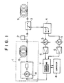
- a fiber Raman laser apparatus 1 includes a laser diode (LD) pumped solid state laser device 11, and an optical fiber 12 connected thereto.
- a light pulse generated by fiber Raman laser apparatus 1 is incident to the optical fiber under test 9 through an optical attenuator 2 and optical coupler or optical switch 3.
- optical switch 3 for example, a sound effect optical switch and the like can be used.
- the Rayleigh backward scattering light generated inside this optical fiber under test 9 is split by the optical coupler or optical switch 3 to be introduced into a spectroscopic device 4.
- two kinds of light waves having different wavelengths are taken out from the spectroscopic device 4, and respectively transformed into electric signals by an optical detector 5.
- the transformed electric signals are amplified by an amplifier 6 to be inputted to a digital averaging circuit 7, which is connected to, and interactively communicates with, a computer 8.
- the digital averaging circuit 7 transmits a trigger signal for generating a light pulse for the LD pumped solid state laser device 11. Synchronizing with a trigger signal, the digital averaging circuit 7 starts sampling of the input signals and conducting an A/D conversion to collect data as to the intensity of the backward scattering by every unit time from the time at which the light pulse entered the optical fiber under test 9.
- the digital averaging circuit 7 is adapted to take an arithmetical average of the data obtained by repetition of the light-pulse incidences, to thereby improve the S/N ratio.
- the data obtained are transmitted to the computer 8 to be subjected to operation processes. Subsequently, the computer 8 displays these data on a display device (not shown in the figure), plotting, for example, data magnitudes in the y-direction against data sampling times in the x-direction.
- a graph is used to illustrate the loss characteristic along the longitudinal direction of the measured optical fiber 9.
- the optical fiber 12 of the fiber Raman laser apparatus 1 is adapted to be provided with a pulse light having a higher output than a threshold above which induced Raman scattering occurs.
- the output of the light pulse should be necessarily more than some watts, but it is difficult for the usual LD to emit light with such a large output power.
- a solid state laser source as well as a gas laser source may emit a high output light pulse, but such apparatuses are bulky and need accessory systems such as a cooling system and the like, thus resulting in impracticality.
- the solid state laser device 11 using LD excitation which has recently been brought into commercial use is employed as the light source of this embodiment.
- This device is one in which a flesh lamp as a light source for exciting the conventional solid state laser is replaced with an LD, which has a good efficiency and can be miniaturized.
- an LD which has a good efficiency and can be miniaturized.
- Nd-doped YAG yttrium aluminum garnet; Y3Al5O12
- Nd-doped YLF yttrium lithium tetra-fluoride
- YLiF4 yttrium lithium tetra-fluoride
- the induced Raman scattering occurs.
- a Rayleigh scattering light wave having the same wavelength as that of the incident light and the Raman scattering light waves having shifted wavelengths.
- the intensity of these scattering light waves increases in proportion to that of the incident light (linear effect).
- the light intensity of the incident light exceeds a certain threshold, there appears non-linear effect, that is, a sharp increase in the light intensity of the Raman scattering light.
- the higher order Stokes light waves which are too faint to be observed in the linear region, become extremely large.
- the components of the Rayleigh light and anti-Stokes light decrease largely, losing their energies in Stokes Light.
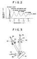
- the distribution of the induced Raman scattering light exhibits an aspect as shown by the dashed curve in Fig.2, having first order, second, third and higher order Stokes light waves generated on the side of longer wavelength than that of the incident light as shown by the solid curve.
- the incident light has a wavelength of 1.32 ⁇ m as stated above, and the wavelengths of the Stokes light waves of the first order, second order, third order and the fourth order, are respectively 1.403 ⁇ m, 1.495 ⁇ m, 1.600 ⁇ m and 1.721 ⁇ m.
- this induced Raman scattering light has and therefore can provide in the wide range of wavelengths an intensity required for the OTDR apparatus greater than some hundreds mili-watts.
- the intensity of the light is considerably high in wavelengths around the troughs and especially in the wavelengths around the peaks.
- the threshold at which the induced Raman scattering becomes dominant is rather low, specifically some tens of watts for multi-mode optical fibers and some watts for single-mode optical fibers.
- the shifts for Stokes light waves of respective orders are determined depending on constituent molecules of the optical fiber such as Si-O and the like.
- the light having a wide range of wavelengths generated in the fiber Raman laser apparatus 1 is provided into the optical fiber 9 under test via the attenuator 2 and the optical coupler or optical switch 3.
- the attenuator 2 is used for regulating the intensity of the incident light lower than the threshold in order to prevent the induced Raman scattering from arising inside the optical fiber under test 9.
- the spectroscopic device 4 is composed of, for example a diffraction grating, an optical filter film having dielectric multi-layers or the like.
- a diffraction grating being used, advantages as follows can be obtained:
- the insertion loss is low, so that it is impossible to make markedly narrow the range of wavelengths of the transmitting light, but the structure is simple so that the device can be miniaturized.
- the spectroscopic device 4 is structured with a diffraction grating 41 as shown in Fig.3.
- This diffraction grating 41 receives light having passed through an optical fiber 43 and a lens 44, and diffracts light to the receiving side.
- two slits 42 are disposed to extract light waves from the light coming from the diffraction grating 41.
- the extracted light waves are introduced using respective optical fibers 43 via respective lenses 44. This arrangement makes it possible to pick up and transmit two kinds of light waves having different wavelengths.
- the induced Raman scattering light having a wide range of wavelengths emitted from the optical fiber 12 of the fiber Raman laser apparatus 1 is incident to the optical fiber 9 under test, which in turn radiates Rayleigh scattering light having a wide range of wavelengths.
- the optical coupler or optical switch 3 is introduced to the spectroscopic device 4.
- the spectroscopic device 4 takes out particular narrowed ranges of wavelengths of the backward scattering light desired to be measured.
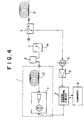
- the light emitted from the optical fiber 12 of the fiber Raman laser apparatus 1 is attenuated by the optical attenuator 2 to be directly subjected to a spectroscopic device 14.
- This spectroscopic device 14 extracts particular narrowed ranges of wavelengths desired to be measured from the induced Raman scattering light emitted from the optical fiber 12 having a wide range of wavelengths.
- the extracted light is introduced to optical fiber under test 9, which, in turn, radiates Rayleigh scattering light having the particular narrowed ranges of wavelengths.
- the obtained backward scattering light is split by the optical coupler or optical switch 3 to be introduced to the optical detector 5.
- the OTDR apparatus of the present embodiment makes it possible to measure the loss of an optical fiber in a range of wavelengths in which the measurement used to be difficult, with a simple method at low cost. Moreover, it is possible for this apparatus alone to perform the measurement in a wide range of wavelengths.
- a dispersion-shift fiber is employed as optical fiber 12, which produces under the influence of the non-linear optical effect the induced Raman scattering light having peaks of the first order Stokes light wave, the second order Stokes light wave, etc. (refer to Fig.2).
- the generated induced Raman scattering light is taken out and introduced into the optical fiber under test 9.
- a single mode fiber is employed as the optical fiber 12
- scattering light having a continuous spectrum of wavelength can be obtained due to its non-linear optical effect.
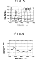
- Fig.5 shows several kinds of light-emission spectra under the influence of the non-linear optical effect, taking the wavelength of light emitted from optical fiber 12 as abscissa and the light intensity (with arbitrary unit) as the ordinate.
- plot L1 shows the spectrum of the light-emission when a dispersion shift fiber (of 50 m length) is used
- plot L2 shows the spectrum when a single mode fiber (of 50 m length) is used
- plot L3 shows the spectrum when a single mode fiber (of 5 m length) is used.
- the incident light is a light pulse having a wavelength of 1.32 ⁇ m and a peak output power of about 100 watts with 30 ns in its pulse width.
- a lengthy single mode fiber produces light having a continuous spectrum of wavelengths ranging from 1.34 to 1.7 ⁇ m, so that the use of an optical fiber of this kind makes it possible to construct an OTDR apparatus in which wavelength is variable.
- light emitted from this non-linear optical fiber 12 and having a continuous spectrum of wavelengths ranging from 1.34 to 1.7 ⁇ m was made to pass through a diffraction grating to obtain light waves each having a wavelength width of 5 nm. The obtained light was introduced into the optical fiber under test 9, and the transmission loss was calculated from the backward scattering light.
- Fig.6 shows a characteristic of transmission loss caused by an optical fiber under test, taking the wavelength of the incident light into the optical fiber under test 9 as abscissa and the transmission loss as ordinate. As apparent from Fig.6, there is an absorption at the wave length of 1.38 ⁇ m, and the loss is minimized in the wavelength band of 1.55 ⁇ m, whereas the loss increases with the wavelengths of 1.65 ⁇ m or more.
Landscapes
- Physics & Mathematics (AREA)
- Optics & Photonics (AREA)
- Chemical & Material Sciences (AREA)
- Analytical Chemistry (AREA)
- General Physics & Mathematics (AREA)
- Engineering & Computer Science (AREA)
- Microelectronics & Electronic Packaging (AREA)
- Testing Of Optical Devices Or Fibers (AREA)
Claims (9)
- OTDR-Gerät, gekennzeichnet durch:eine Lichtquelle (11) zum Erzeugen eines Lichtpulses;eine optische Faser (12) mit einem ersten Ende und einem zweiten Ende zum Empfangen des Lichtpulses an dem ersten Ende und zum Emittieren von wellenlängenverschobenen Licht, das Wellenlängen aufweist, die von dem empfangenen Lichtpuls unter dem Einfluß des nichtlinearen optischen Effektes verschoben sind, von dem anderen Ende desselben;wobei die optische Faser (12) aus einer langen optischen Einmodenfaser derart gemacht ist, daß das wellenlängenverschobene Licht ein kontinuierliches Wellenspektrum ohne wesentliche Spitzen aufweist;ein Einführungs- und Extraktionsmittel (3) zum Einführen des wellenlängenverschobenen Lichtes in eine zu testende optische Faser (9) und Extrahieren des von der zu testenden optischen Faser (9) emittierten rückwärts gestreuten Lichtes;optische Detektoren (5) zum Transformieren des rückwärts gestreuten Lichtes in elektrische Signale undein Verarbeitungsmittel (6, 7, 8) zum Analysieren des erfaßten Signales von den optischen Detektoren mit dem Ablauf der Zeit zum Erhalten einer Verlusteigenschaft der zu testenden optischen Faser.
- OTDR-Gerät nach Anspruch 1, dadurch gekennzeichnet, daß die Lichtquelle eine Festkörperlasereinrichtung (11) ist, die einen Laserstrahl durch eine Laserdiode anregt.
- OTDR-Gerät nach Anspruch 1 oder 2, dadurch gekennzeichnet, daß das Einführungs- und Extraktionsmittel einen Optokuppler oder optischen Schalter (3) enthält, der das wellenlängenverschobene Licht in die zu testende optische Faser (9) einführt und das von der zu testenden optischen Faser (9) emittierte rückwärts gestreute Licht so aufspaltet, daß es in die optischen Detektoren (5) eingeführt wird.
- OTDR-Gerät nach Anspruch 3, dadurch gekennzeichnet, daß das Einführungs- und Extraktionsmittel eine erste spektroskopische Einrichtung (4) enthält, die das rückwärts gestreute Licht in ihre Spektralkomponenten zerlegt und Lichtwellen, die vorbestimmte Wellenlängen aufweisen, so extrahiert, daß sie in die optischen Detektoren (5) eingeführt werden.
- OTDR-Gerät nach Anspruch 3, dadurch gekennzeichnet, daß das Einführungs- und Extraktionsmittel eine zweite spektroskopische Einrichtung (14) enthält, die das wellenlängenverschobene Licht in seine Spektralkomponenten zerlegt und Lichtwellen, die vorbestimmte Wellenlängen aufweisen, so extrahiert, daß sie in den Optokuppler oder optischen Schalter (3) eingeführt werden.
- OTDR-Gerät nach Anspruch 1, dadurch gekennzeichnet, daß das Verarbeitungsmittel die Verlusteigenschaft der zu testenden optischen Faser (9) durch Abtasten des erfaßten Signales von den optischen Detektoren (5) während jeder Einheit der Zeitdauer bestimmt und die erhaltenen Daten in bezug auf den Ablauf der Zeit analysiert.
- OTDR-Gerät nach Anspruch 6, dadurch gekennzeichnet, daß das Verarbeitungsmittel (7) zu der Lichtquelle (11) ein Triggersignal zum Erzeugen des Lichtpulses überträgt und die Verarbeitung des rückwärts gestreuten Lichtes mit dem Ablauf der Zeit beginnt, in dem der Moment, an dem das Triggersignal erzeugt ist, als ein Ursprungszeitpunkt angenommen wird.
- OTDR-Gerät nach Anspruch 7, dadurch gekennzeichnet, daß das Verarbeitungsmittel (7) Daten verarbeitet, in dem ein arithmetisches Mittel der Messungen des rückwärts gestreuten Lichtes entsprechend einer Mehrzahl von Lichtpulsen genommen wird.
- OTDR-Gerät nach einem der Ansprüche 1 bis 8, mit einem Dämpfungsglied (2) zum Regeln der Intensität des wellenlängenverschobenen Lichtes, das auf die zu testende optische Faser (9) einfallen soll.
Applications Claiming Priority (2)
| Application Number | Priority Date | Filing Date | Title |
|---|---|---|---|
| JP3061230A JPH04274724A (ja) | 1991-03-02 | 1991-03-02 | Otdr装置 |
| JP61230/91 | 1991-03-02 |
Publications (2)
| Publication Number | Publication Date |
|---|---|
| EP0502422A1 EP0502422A1 (de) | 1992-09-09 |
| EP0502422B1 true EP0502422B1 (de) | 1996-05-22 |
Family
ID=13165212
Family Applications (1)
| Application Number | Title | Priority Date | Filing Date |
|---|---|---|---|
| EP92103352A Expired - Lifetime EP0502422B1 (de) | 1991-03-02 | 1992-02-27 | Optisches Zeitbereichsflektometer |
Country Status (4)
| Country | Link |
|---|---|
| US (1) | US5323224A (de) |
| EP (1) | EP0502422B1 (de) |
| JP (1) | JPH04274724A (de) |
| DE (1) | DE69210864T2 (de) |
Cited By (1)
| Publication number | Priority date | Publication date | Assignee | Title |
|---|---|---|---|---|
| US8005323B2 (en) | 2003-02-12 | 2011-08-23 | Sensornet Limited | Method and apparatus for generation and transmission of high energy optical pulses for long range measurements |
Families Citing this family (36)
| Publication number | Priority date | Publication date | Assignee | Title |
|---|---|---|---|---|
| JPH06273273A (ja) * | 1993-03-17 | 1994-09-30 | Ando Electric Co Ltd | ラマン散乱光を表示する光パルス試験器 |
| US5401956A (en) * | 1993-09-29 | 1995-03-28 | United Technologies Corporation | Diagnostic system for fiber grating sensors |
| US5500908A (en) * | 1994-04-14 | 1996-03-19 | U.S. Philips Corporation | Optical switch and transmitter and receiver for a multiplex transmission system including such a switch |
| US5444801A (en) * | 1994-05-27 | 1995-08-22 | Laughlin; Richard H. | Apparatus for switching optical signals and method of operation |
| US5875271A (en) * | 1994-05-27 | 1999-02-23 | Optical Switch Corporation | Apparatus for switching optical signals and method of operation |
| US5589933A (en) * | 1994-10-24 | 1996-12-31 | Photon Kinetics, Inc. | Optical fiber test instrument with mechanically positioned attenuator |
| US5909301A (en) * | 1995-06-07 | 1999-06-01 | Optical Switch Corporation | Frustrated total internal reflection device having a first spacer and a second spacer |
| US5841916A (en) * | 1995-06-07 | 1998-11-24 | Optical Switch Corporation | Frustrated total internal reflection device |
| US5917641A (en) * | 1995-06-07 | 1999-06-29 | Optical Switch Corporation | Frustrated total internal reflection device having a spacer and an endplate |
| US5801830A (en) * | 1996-02-14 | 1998-09-01 | Wavelinq, Inc. | Apparatus and associated methods of detecting optical carriers and measuring characteristics thereof |
| DE19649594A1 (de) | 1996-11-29 | 1998-06-04 | Deutsche Telekom Ag | Optisches Impulsreflektometer |
| US6687632B1 (en) | 1998-01-23 | 2004-02-03 | Trilithic, Inc. | Testing of CATV systems |
| US6236787B1 (en) | 1998-07-08 | 2001-05-22 | Optical Switch Corporation | Method and apparatus for aligning optical fibers using an alignment spacer |
| US6137930A (en) * | 1998-07-08 | 2000-10-24 | Optical Switch Corporation | Method and apparatus for aligning optical fibers |
| US6253007B1 (en) | 1998-07-08 | 2001-06-26 | Optical Switch Corporation | Method and apparatus for connecting optical fibers |
| US6236778B1 (en) | 1998-12-16 | 2001-05-22 | Optical Switch Corporation | Frustrated total internal reflection bus and method of operation |
| US6243511B1 (en) | 1999-02-04 | 2001-06-05 | Optical Switch Corporation | System and method for determining the condition of an optical signal |
| KR100343812B1 (ko) * | 2000-09-21 | 2002-07-20 | 광주과학기술원 | 광섬유의 색분산 측정시스템 및 측정방법 |
| FR2817960B1 (fr) * | 2000-12-13 | 2003-04-04 | Acome Soc Coop Travailleurs | Reflectometre a plusieurs longueurs d'ondes |
| JP3587176B2 (ja) * | 2001-04-02 | 2004-11-10 | 日本電気株式会社 | ラマン増幅器及びラマン増幅方法 |
| JP2003204303A (ja) | 2001-11-02 | 2003-07-18 | Nippon Telegr & Teleph Corp <Ntt> | 分散検知装置および分散検知方法 |
| GB2416588B (en) * | 2002-01-30 | 2006-06-21 | Sensor Highway Ltd | Optical time domain reflectometry |
| GB0202159D0 (en) * | 2002-01-30 | 2002-03-20 | Sensor Highway Ltd | OPtical time domain reflectometry |
| JP2003254864A (ja) * | 2002-03-04 | 2003-09-10 | Ando Electric Co Ltd | 波長依存性測定装置 |
| GB0303155D0 (en) * | 2003-02-12 | 2003-03-19 | Sensornet Ltd | Distributed sensor |
| EP1876435A1 (de) | 2006-07-06 | 2008-01-09 | Agilent Technologies, Inc. | Ermittlung optischer Verluste mittels optische Reflektometrie |
| LT2577890T (lt) | 2010-05-27 | 2019-05-27 | Exfo Inc. | Daugybinio rinkimo otdr būdas ir įtaisas |
| US9391695B2 (en) | 2013-07-10 | 2016-07-12 | Neophotonics Corporation | Optical network communication system with embedded optical time domain reflectometer and method of operation thereof |
| CN103575504A (zh) * | 2013-11-25 | 2014-02-12 | 南京大学 | 基于超导纳米线单光子探测器的光时域反射计 |
| CN104198160B (zh) * | 2014-09-01 | 2016-06-29 | 江苏宇特光电科技股份有限公司 | 一种窄线宽波长可调谐光时域反射计及其控制方法 |
| US9641243B2 (en) | 2015-02-23 | 2017-05-02 | Exfo Inc. | Safe-mode OTDR method |
| CN109813528A (zh) * | 2019-03-18 | 2019-05-28 | 中国科学院上海光学精密机械研究所 | 基于光时域反射原理的光纤激光器损耗检测方法 |
| US12320725B2 (en) * | 2020-08-21 | 2025-06-03 | Nippon Telegraph And Telephone Corporation | Several mode fiber test method and several mode fiber test device |
| JP7320022B2 (ja) * | 2021-04-22 | 2023-08-02 | 横河電機株式会社 | 光パルス試験器 |
| CN115524099B (zh) * | 2022-09-05 | 2023-06-09 | 武汉敏芯半导体股份有限公司 | 半导体激光器的测试方法、装置、计算机设备及存储介质 |
| US12208316B2 (en) | 2022-12-06 | 2025-01-28 | Acushnet Company | Multi-piece golf club head |
Family Cites Families (13)
| Publication number | Priority date | Publication date | Assignee | Title |
|---|---|---|---|---|
| US4063106A (en) * | 1977-04-25 | 1977-12-13 | Bell Telephone Laboratories, Incorporated | Optical fiber Raman oscillator |
| JPS5478156A (en) * | 1977-12-05 | 1979-06-22 | Hitachi Ltd | Detector of break point of optical fibers |
| GB2156513B (en) * | 1984-03-28 | 1988-05-25 | Plessey Co Plc | Temperature measuring arrangements |
| JPS60237339A (ja) * | 1984-05-11 | 1985-11-26 | Nec Corp | 光回路評価装置 |
| US4761786A (en) * | 1986-12-23 | 1988-08-02 | Spectra-Physics, Inc. | Miniaturized Q-switched diode pumped solid state laser |
| GB2179733B (en) * | 1985-08-29 | 1989-08-09 | Stc Plc | Plural wavelength optical fibre reflectometer |
| JPS62207927A (ja) * | 1986-03-10 | 1987-09-12 | Yokogawa Electric Corp | 光フアイバ測定器 |
| US4859844A (en) * | 1988-02-24 | 1989-08-22 | Hughes Aircraft Company | Comb filter pressure/temperature sensing system |
| JP2890478B2 (ja) * | 1989-06-01 | 1999-05-17 | 東陶機器株式会社 | 気泡発生浴槽の浴湯循還ポンプ駆動回路 |
| US5189483A (en) * | 1989-02-28 | 1993-02-23 | Fujitsu Limited | Apparatus for measurement of chromatic dispersion in a single mode optical fiber |
| JPH034857A (ja) * | 1989-06-01 | 1991-01-10 | Toto Ltd | 気泡発生浴槽の機能部ケース |
| US5028775A (en) * | 1989-06-30 | 1991-07-02 | Anritsu Corporation | Optical time domain reflectometer using optical element with three control modes of oscillation, attenuation and amplification |
| US5179420A (en) * | 1991-06-07 | 1993-01-12 | Bell Canada | Optical time domain reflectometer using a tunable optical source |
-
1991
- 1991-03-02 JP JP3061230A patent/JPH04274724A/ja active Pending
-
1992
- 1992-02-27 DE DE69210864T patent/DE69210864T2/de not_active Expired - Fee Related
- 1992-02-27 EP EP92103352A patent/EP0502422B1/de not_active Expired - Lifetime
- 1992-03-02 US US07/844,291 patent/US5323224A/en not_active Expired - Lifetime
Cited By (1)
| Publication number | Priority date | Publication date | Assignee | Title |
|---|---|---|---|---|
| US8005323B2 (en) | 2003-02-12 | 2011-08-23 | Sensornet Limited | Method and apparatus for generation and transmission of high energy optical pulses for long range measurements |
Also Published As
| Publication number | Publication date |
|---|---|
| JPH04274724A (ja) | 1992-09-30 |
| DE69210864T2 (de) | 1996-11-21 |
| DE69210864D1 (de) | 1996-06-27 |
| US5323224A (en) | 1994-06-21 |
| EP0502422A1 (de) | 1992-09-09 |
Similar Documents
| Publication | Publication Date | Title |
|---|---|---|
| EP0502422B1 (de) | Optisches Zeitbereichsflektometer | |
| EP1338877B1 (de) | Optische Reflexionsmessung im Zeitbereich | |
| US6433922B1 (en) | Apparatus and method for a self adjusting Raman amplifier | |
| JP2575324B2 (ja) | 光ファイバ式温度分布測定装置 | |
| EP0681172B1 (de) | Verfahren und Apparat zur Messung der Wellenlängen mit Null-Dispersion in einer optischen Faser | |
| US8693512B2 (en) | Frequency referencing for tunable lasers | |
| EP1562028B1 (de) | Einrichtung zur optischen spektralanalyse mittels optischer verstärkung durch brillouin-streuung und entsprechendes messverfahren | |
| JP2769185B2 (ja) | 後方散乱光測定装置 | |
| CA2392308A1 (en) | System and method for resolving polarization mode dispersion in optical fibers | |
| CA2295780C (en) | Wavelength measuring system | |
| JP3340849B2 (ja) | 光学式時系列反射測定方法及び装置 | |
| CN105783955A (zh) | 基于高阶斯托克斯波的灵敏度可调分布式光纤传感系统 | |
| JP3236661B2 (ja) | 光パルス試験器 | |
| GB2277147A (en) | Optical fibre distributed sensing | |
| CN105865498B (zh) | 基于自激发布里渊激光器的高灵敏分布式光纤传感系统 | |
| JP2005283372A (ja) | Ase光源とラマン増幅を使用したfbgによる温度または歪み測定装置 | |
| JP3248559B2 (ja) | 光ファイバ零分散波長分布の測定方法および測定装置 | |
| CN106768898B (zh) | 一种基于掺铒光纤激光器的调q特性的检测方法 | |
| CN111537069A (zh) | 一种具有分布式测温功能的太赫兹时域光谱和成像系统 | |
| Philen | Measurement of the Non-Linear Index of Refraction, N2 | |
| Cowle et al. | Optical fiber sources, amplifiers, and special fibers for application in multiplexed and distributed sensor systems | |
| JPH071221B2 (ja) | 後方散乱光測定装置 | |
| CN119812923A (zh) | 基于随机光纤激光器的u波段相关光时域反射仪 | |
| JP2713672B2 (ja) | 光増幅器雑音指数測定装置 | |
| JPH09105701A (ja) | 光ファイバ歪測定装置 |
Legal Events
| Date | Code | Title | Description |
|---|---|---|---|
| PUAI | Public reference made under article 153(3) epc to a published international application that has entered the european phase |
Free format text: ORIGINAL CODE: 0009012 |
|
| 17P | Request for examination filed |
Effective date: 19920710 |
|
| AK | Designated contracting states |
Kind code of ref document: A1 Designated state(s): DE FR GB IT |
|
| 17Q | First examination report despatched |
Effective date: 19931015 |
|
| GRAH | Despatch of communication of intention to grant a patent |
Free format text: ORIGINAL CODE: EPIDOS IGRA |
|
| GRAA | (expected) grant |
Free format text: ORIGINAL CODE: 0009210 |
|
| AK | Designated contracting states |
Kind code of ref document: B1 Designated state(s): DE FR GB IT |
|
| ET | Fr: translation filed | ||
| REF | Corresponds to: |
Ref document number: 69210864 Country of ref document: DE Date of ref document: 19960627 |
|
| ITF | It: translation for a ep patent filed | ||
| PLBE | No opposition filed within time limit |
Free format text: ORIGINAL CODE: 0009261 |
|
| STAA | Information on the status of an ep patent application or granted ep patent |
Free format text: STATUS: NO OPPOSITION FILED WITHIN TIME LIMIT |
|
| 26N | No opposition filed | ||
| PGFP | Annual fee paid to national office [announced via postgrant information from national office to epo] |
Ref country code: DE Payment date: 19991228 Year of fee payment: 9 |
|
| PGFP | Annual fee paid to national office [announced via postgrant information from national office to epo] |
Ref country code: FR Payment date: 20000118 Year of fee payment: 9 |
|
| PGFP | Annual fee paid to national office [announced via postgrant information from national office to epo] |
Ref country code: GB Payment date: 20000121 Year of fee payment: 9 |
|
| PG25 | Lapsed in a contracting state [announced via postgrant information from national office to epo] |
Ref country code: GB Free format text: LAPSE BECAUSE OF NON-PAYMENT OF DUE FEES Effective date: 20010227 |
|
| GBPC | Gb: european patent ceased through non-payment of renewal fee |
Effective date: 20010227 |
|
| PG25 | Lapsed in a contracting state [announced via postgrant information from national office to epo] |
Ref country code: FR Free format text: LAPSE BECAUSE OF NON-PAYMENT OF DUE FEES Effective date: 20011031 |
|
| REG | Reference to a national code |
Ref country code: FR Ref legal event code: ST |
|
| PG25 | Lapsed in a contracting state [announced via postgrant information from national office to epo] |
Ref country code: DE Free format text: LAPSE BECAUSE OF NON-PAYMENT OF DUE FEES Effective date: 20011201 |
|
| PG25 | Lapsed in a contracting state [announced via postgrant information from national office to epo] |
Ref country code: IT Free format text: LAPSE BECAUSE OF NON-PAYMENT OF DUE FEES;WARNING: LAPSES OF ITALIAN PATENTS WITH EFFECTIVE DATE BEFORE 2007 MAY HAVE OCCURRED AT ANY TIME BEFORE 2007. THE CORRECT EFFECTIVE DATE MAY BE DIFFERENT FROM THE ONE RECORDED. Effective date: 20050227 |