EP0501410A1 - Cutting tool - Google Patents
Cutting tool Download PDFInfo
- Publication number
- EP0501410A1 EP0501410A1 EP92103157A EP92103157A EP0501410A1 EP 0501410 A1 EP0501410 A1 EP 0501410A1 EP 92103157 A EP92103157 A EP 92103157A EP 92103157 A EP92103157 A EP 92103157A EP 0501410 A1 EP0501410 A1 EP 0501410A1
- Authority
- EP
- European Patent Office
- Prior art keywords
- insert
- layer
- cutting
- receiving seat
- cutting tool
- Prior art date
- Legal status (The legal status is an assumption and is not a legal conclusion. Google has not performed a legal analysis and makes no representation as to the accuracy of the status listed.)
- Granted
Links
Images


Classifications
-
- B—PERFORMING OPERATIONS; TRANSPORTING
- B23—MACHINE TOOLS; METAL-WORKING NOT OTHERWISE PROVIDED FOR
- B23B—TURNING; BORING
- B23B27/00—Tools for turning or boring machines; Tools of a similar kind in general; Accessories therefor
- B23B27/14—Cutting tools of which the bits or tips or cutting inserts are of special material
- B23B27/16—Cutting tools of which the bits or tips or cutting inserts are of special material with exchangeable cutting bits or cutting inserts, e.g. able to be clamped
- B23B27/1666—Cutting tools of which the bits or tips or cutting inserts are of special material with exchangeable cutting bits or cutting inserts, e.g. able to be clamped with plate-like cutting inserts clamped by a clamping member acting almost perpendicularly on chip-forming plane
-
- B—PERFORMING OPERATIONS; TRANSPORTING
- B23—MACHINE TOOLS; METAL-WORKING NOT OTHERWISE PROVIDED FOR
- B23C—MILLING
- B23C5/00—Milling-cutters
- B23C5/003—Milling-cutters with vibration suppressing means
-
- B—PERFORMING OPERATIONS; TRANSPORTING
- B23—MACHINE TOOLS; METAL-WORKING NOT OTHERWISE PROVIDED FOR
- B23C—MILLING
- B23C5/00—Milling-cutters
- B23C5/16—Milling-cutters characterised by physical features other than shape
- B23C5/20—Milling-cutters characterised by physical features other than shape with removable cutter bits or teeth or cutting inserts
- B23C5/22—Securing arrangements for bits or teeth or cutting inserts
- B23C5/2265—Securing arrangements for bits or teeth or cutting inserts by means of a wedge
- B23C5/2269—Securing arrangements for bits or teeth or cutting inserts by means of a wedge for plate-like cutting inserts
-
- B—PERFORMING OPERATIONS; TRANSPORTING
- B23—MACHINE TOOLS; METAL-WORKING NOT OTHERWISE PROVIDED FOR
- B23C—MILLING
- B23C2210/00—Details of milling cutters
- B23C2210/16—Fixation of inserts or cutting bits in the tool
- B23C2210/166—Shims
-
- Y—GENERAL TAGGING OF NEW TECHNOLOGICAL DEVELOPMENTS; GENERAL TAGGING OF CROSS-SECTIONAL TECHNOLOGIES SPANNING OVER SEVERAL SECTIONS OF THE IPC; TECHNICAL SUBJECTS COVERED BY FORMER USPC CROSS-REFERENCE ART COLLECTIONS [XRACs] AND DIGESTS
- Y10—TECHNICAL SUBJECTS COVERED BY FORMER USPC
- Y10T—TECHNICAL SUBJECTS COVERED BY FORMER US CLASSIFICATION
- Y10T407/00—Cutters, for shaping
- Y10T407/13—Yieldable tool
-
- Y—GENERAL TAGGING OF NEW TECHNOLOGICAL DEVELOPMENTS; GENERAL TAGGING OF CROSS-SECTIONAL TECHNOLOGIES SPANNING OVER SEVERAL SECTIONS OF THE IPC; TECHNICAL SUBJECTS COVERED BY FORMER USPC CROSS-REFERENCE ART COLLECTIONS [XRACs] AND DIGESTS
- Y10—TECHNICAL SUBJECTS COVERED BY FORMER USPC
- Y10T—TECHNICAL SUBJECTS COVERED BY FORMER US CLASSIFICATION
- Y10T407/00—Cutters, for shaping
- Y10T407/22—Cutters, for shaping including holder having seat for inserted tool
- Y10T407/2272—Cutters, for shaping including holder having seat for inserted tool with separate means to fasten tool to holder
Definitions
- the present invention relates to cutting tools having a releasible and disposable cutting insert secured to an insert-receiving seat, including milling cutters and the like. Particularly, the present invention relates to a cutting tool having a positioning block between the cutting insert and the insert-receiving seat.
- the cutting tool comprises a tool body 1 having an insert-receiving seat or recess 2 formed at its forward end.
- the tool body 1 also has a L-shaped lever 3 provided in a hole opening to the insert-receiving seat 2 and a bolt 4 provided in a hole adjoined to the first hole.
- a throwaway cutting insert 6 with a mounting bore 7 formed therethrough is received on the insert receiving seat 2, while the L-shaped lever 3 is received in the first hole so as to protrude its head portion 5 from the seat 2 to engage with the mounting bore 7 of the insert 6 when the end portion of the lever 3 is pushed downwardly by the bolt 4.
- a positioning block 8 is provided between the insert 6 and the seat 2.
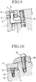
- FIG 10 depicts another type of the conventional insert-clamped cutting tool which comprises a tool body 10 having an insert receiving seat or recess 11 formed at its forward end and a bolt-receiving hole opening on the insert-receiving seat 11.
- a positioning block 12 with a bore formed therethrough is provided on the insert receiving seat 11, and a bolt 13 is inserted through the bore to engage the bolt therewith.
- a throwaway cutting insert 14 is mounted on the positioning block 12 and pressed against the seat 11 by clamping means including a clamp 15 and a clamping bolt 16.
- the positioning blocks 8 and 12 are made of materials such as cemented carbide, high speed steel or the like. Accordingly, these conventional blocks are characterized by their hardness which is lower than that of the cutting insert but higher than that of the surface of the seat to avoid wearing the insert down.
- the conventional positioning block is made of hard material and thus it is difficult to absorb severe vibration of the cutting insert during the milling process. Consequently, the conventional cutting tool using the above described positioning block has some problems i.e., slipping off of the insert from the insert-receiving seat, damaging the cutting edge of the insert, chipping the insert, or the like, caused by the vibration of the cutting insert.
- a cutting tool comprising (a) a tool body having a recess formed at a forward end thereof and defining a insert-receiving seat; (b) a cutting insert; (c) a positioning block to be placed between the cutting insert and the insert-receiving seat, having a top and bottom faces and having a hardness thereof which is lower than that of a surface of insert-receiving seat; and (d) clamp means for securing said cutting insert and the positioning block on said insert-receiving seat.
- the above described positioning block is able to absorb some extent of vibration of the cutting insert during the milling process.
- the cutting tool in which a positioning block has two layers.
- a hardness of a surface of the insert-receiving seat is higher than that of the first layer but lower than that of the second layer.
- a first preferred embodiment of the cutting tool in accordance with the present invention comprises a tool body 20 having recess formed at its forward end and defining an insert-receiving seat 21, a throwaway cutting insert 22 which can be fixed on the seat and replaced regularly, a positioning block 23 which is interposed between the insert-receiving seat 21 and the cutting insert 23, and clamp means including a clamp 24 and a bolt 25.
- the cutting insert 23 and top and bottom faces of the positioning block 22 have the same shape to each other.
- a hardness of the positioning block is lower than that of a surface of the insert-receiving seat for absorbing some extent of vibration of the cutting insert during the milling process.
- the cutting insert 23 is fixed on the insert-receiving seat 22 by clamp means 24 and 25.
- the clamp 24 is disposed at a position shifted rearward of the tool body 20 relative to the insert-receiving seat 21 and is connected with the tool body 20 via a bolt 25.
- the clamp bolt 25 when the clamp bolt 25 is tightened, the insert 23 and the positioning block are pressed by the clamp 24 against the insert-receiving seat 23.
- FIG. 2 shows a cutting tool of FIG 1 except that the positioning block 22 comprises two layers i.e., a first layer 22a which is on the side of the insert-receiving seat 21 and a second layer 22b which is on the side of the cutting insert 23.
- the first layer 22a is characterized by having a thickness lower than that of the second layer 22b and is made of a soft metal such as copper, aluminum or the like.
- This first layer 22a is not only responsible for absorbing undesirable vibrations and shocks which act on the cutting insert 23 during the milling operation by its elastic property but also for preventing the wear of the insert-receiving seat 21.
- the second layer 22b is made of a high-hardness material such as cemented carbide, high speed steel or the like, and is responsible for preventing the wear of the positioning block.
- a hardness of a surface of the insert-receiving seat 21 is higher than that of the first layer 22a but lower than that of the second layer 22b.
- FIG. 3 shows the third preferred embodiment of the same invention as illustrated in FIG. 2 except that the positioning block 30 has a first layer 30a with a thickness larger than that of a second layer 30b. Therefore, comparing with the second embodiment of the present invention, severe vibration of the insert 23 can be absorbed more effectively by the positioning block 22 having a thickness of the soft layer 30a which is thicker than that of the hard layer 30b.
- the positioning block 22 having a thickness of the soft layer 30a which is thicker than that of the hard layer 30b.
- a size change of the block 22 is hardly occurred, because a thickness of the soft layer 22a is smaller than that of the hard layer 22b and thus milling operation can be performed with accuracy.
- FIG. 4 shows a fourth preferred embodiment of the same invention as illustrated in FIGS. 1 - 3 except that the positioning block 40 comprises a first layer 40a which is on the side of the cutting insert 23 and a second layer 40b which is on the side of the insert-receiving seat 21.
- the first layer 40a is characterized by having a thickness smaller than that of the second layer 40b and is made of a soft metal such as copper, aluminum or the like.
- the second layer 40b is made of a high-hardness material such as cemented carbide, high speed steel or the like. It is noted that the first layer 40a of the block is easily formed into various shapes by means of press and thus this layer 40 also responsible to fit to the shape of the insert to be attached.
- the throwaway cutting insert 23 having top and bottom faces in the form of square. As shown in FIGS. 5 and 6, these faces are provided as rake faces where cutting edges 26 are formed on ridge lines thereof.
- the insert 23 can be attached on a surface of the first layer 40b by an attaching portion 28 thereof which is surrounded by the above mentioned grooves 27.
- the cutting tool according to the present invention has a positioning block including two different layers and a surface-modified cutting insert.
- the cutting tool of the present invention has the advantage of increasing the reliability of operation. It will be understood that other embodiments and modifications of the invention are contemplated. It is the intention to include all such embodiment and modifications within the scope of the invention as are defined by the appended claims.
Abstract
According to the present invention, there is also provided the cutting tool in which a positioning block (23) has two layers. A hardness of a surface of the insert-receiving seat is higher than that of the first layer but is lower than that of the second layer.
Description
- The present invention relates to cutting tools having a releasible and disposable cutting insert secured to an insert-receiving seat, including milling cutters and the like. Particularly, the present invention relates to a cutting tool having a positioning block between the cutting insert and the insert-receiving seat.
- There are two basic types of insert-clamped cutting tools provided with the disposable cutting inserts.
- For one type of conventional cutting tools, for example, a lever clamping type byte is depicted in FIG 9. In this figure, the cutting tool comprises a tool body 1 having an insert-receiving seat or recess 2 formed at its forward end. The tool body 1 also has a L-
shaped lever 3 provided in a hole opening to the insert-receiving seat 2 and abolt 4 provided in a hole adjoined to the first hole. In this example, a throwaway cutting insert 6 with a mounting bore 7 formed therethrough is received on the insert receiving seat 2, while the L-shaped lever 3 is received in the first hole so as to protrude itshead portion 5 from the seat 2 to engage with the mounting bore 7 of theinsert 6 when the end portion of thelever 3 is pushed downwardly by thebolt 4. In this example, apositioning block 8 is provided between theinsert 6 and the seat 2. - FIG 10 depicts another type of the conventional insert-clamped cutting tool which comprises a
tool body 10 having an insert receiving seat or recess 11 formed at its forward end and a bolt-receiving hole opening on the insert-receiving seat 11. Apositioning block 12 with a bore formed therethrough is provided on the insert receiving seat 11, and abolt 13 is inserted through the bore to engage the bolt therewith. Furthermore, athrowaway cutting insert 14 is mounted on thepositioning block 12 and pressed against the seat 11 by clamping means including aclamp 15 and aclamping bolt 16. - In general, the
positioning blocks - However, the conventional positioning block is made of hard material and thus it is difficult to absorb severe vibration of the cutting insert during the milling process. Consequently, the conventional cutting tool using the above described positioning block has some problems i.e., slipping off of the insert from the insert-receiving seat, damaging the cutting edge of the insert, chipping the insert, or the like, caused by the vibration of the cutting insert.
- It is therefore an object of the present invention to reduce or resolve the above described problems and to achieve an increase in reliability of operation by providing a particularly advantageous construction of the positioning block inserted between the cutting insert and the insert-receiving seat.
- According to the present invention, there is provided a cutting tool comprising (a) a tool body having a recess formed at a forward end thereof and defining a insert-receiving seat; (b) a cutting insert; (c) a positioning block to be placed between the cutting insert and the insert-receiving seat, having a top and bottom faces and having a hardness thereof which is lower than that of a surface of insert-receiving seat; and (d) clamp means for securing said cutting insert and the positioning block on said insert-receiving seat. The above described positioning block is able to absorb some extent of vibration of the cutting insert during the milling process.
- According to the present invention, there is also provided the cutting tool in which a positioning block has two layers. In this case, a hardness of a surface of the insert-receiving seat is higher than that of the first layer but lower than that of the second layer.
- In order that the invention may be readily carried into effect, it will now be described with reference to the accompanying drawings, wherein:
- FIG. 1 is a fragmentary cross sectional view of a cutting tool in accordance with the present invention;
- FIG. 2 is a fragmentary cross sectional view of the cutting tool as shown in FIG. 1 except that the positioning block comprises two layer;
- FIG. 3 is a fragmentary cross sectional view of the cutting tool as shown in FIGS. 1 and 2 except that the positioning block has a first layer with a thickness larger than that of a second layer;
- FIG. 4 is a fragmentary cross sectional view of the cutting tool as shown in FIGS. 1-3 except that the positioning block comprises a first layer on the side of the cutting insert;
- FIG. 5 is a plan view of a cutting insert having grooves on top and bottom faces thereof in accordance with the present invention;
- FIG. 6 is a plan view of another cutting insert as shown in FIG. 5 except that the insert has a different pattern of grooves;
- FIG. 7 is a fragmentary cross sectional view of the cutting tool having a cutting insert of FIG. 5 or 6 in accordance with the present invention;
- FIG. 8 is a fragmentary cross sectional view of the cutting tool as shown in FIG. 7 except that the positioning insert has
- FIG. 9 is a fragmentary cross sectional view of a conventional cutting tool, a lever clamping type bite; and
- FIG. 10 is a fragmentary cross sectional view of another type of the conventional cutting tool.
- Referring to FIG. 1, a first preferred embodiment of the cutting tool in accordance with the present invention comprises a
tool body 20 having recess formed at its forward end and defining an insert-receivingseat 21, athrowaway cutting insert 22 which can be fixed on the seat and replaced regularly, apositioning block 23 which is interposed between the insert-receivingseat 21 and thecutting insert 23, and clamp means including aclamp 24 and abolt 25. In this embodiment, the cutting insert 23 and top and bottom faces of thepositioning block 22 have the same shape to each other. In addition, a hardness of the positioning block is lower than that of a surface of the insert-receiving seat for absorbing some extent of vibration of the cutting insert during the milling process. - In the above described cutting tool as illustrated in FIG.1, the
cutting insert 23 is fixed on the insert-receivingseat 22 by clamp means 24 and 25. Theclamp 24 is disposed at a position shifted rearward of thetool body 20 relative to the insert-receivingseat 21 and is connected with thetool body 20 via abolt 25. In the cutting tool described above, when theclamp bolt 25 is tightened, theinsert 23 and the positioning block are pressed by theclamp 24 against the insert-receivingseat 23. - FIG. 2 shows a cutting tool of FIG 1 except that the
positioning block 22 comprises two layers i.e., a first layer 22a which is on the side of the insert-receivingseat 21 and a second layer 22b which is on the side of thecutting insert 23. In this embodiment, the first layer 22a is characterized by having a thickness lower than that of the second layer 22b and is made of a soft metal such as copper, aluminum or the like. This first layer 22a is not only responsible for absorbing undesirable vibrations and shocks which act on the cutting insert 23 during the milling operation by its elastic property but also for preventing the wear of the insert-receivingseat 21. On the other hand, the second layer 22b is made of a high-hardness material such as cemented carbide, high speed steel or the like, and is responsible for preventing the wear of the positioning block. - It is noted that a hardness of a surface of the insert-receiving
seat 21 is higher than that of the first layer 22a but lower than that of the second layer 22b. - FIG. 3 shows the third preferred embodiment of the same invention as illustrated in FIG. 2 except that the
positioning block 30 has a first layer 30a with a thickness larger than that of asecond layer 30b. Therefore, comparing with the second embodiment of the present invention, severe vibration of theinsert 23 can be absorbed more effectively by thepositioning block 22 having a thickness of the soft layer 30a which is thicker than that of thehard layer 30b. In the case of the second embodiment of the present invention, on the other hand, in spite of the fact that a shape of the first layer 22a is elastically changed by the vibration during the milling process, a size change of theblock 22 is hardly occurred, because a thickness of the soft layer 22a is smaller than that of the hard layer 22b and thus milling operation can be performed with accuracy. - FIG. 4 shows a fourth preferred embodiment of the same invention as illustrated in FIGS. 1 - 3 except that the
positioning block 40 comprises afirst layer 40a which is on the side of thecutting insert 23 and asecond layer 40b which is on the side of the insert-receivingseat 21. Thefirst layer 40a is characterized by having a thickness smaller than that of thesecond layer 40b and is made of a soft metal such as copper, aluminum or the like. On the other hand, thesecond layer 40b is made of a high-hardness material such as cemented carbide, high speed steel or the like. It is noted that thefirst layer 40a of the block is easily formed into various shapes by means of press and thus thislayer 40 also responsible to fit to the shape of the insert to be attached. - In the cutting tool according to the present invention, the throwaway cutting insert 23 having top and bottom faces in the form of square. As shown in FIGS. 5 and 6, these faces are provided as rake faces where
cutting edges 26 are formed on ridge lines thereof. For holding the cutting insert 23 on the insert-receivingseat 22, there are several grooves ornotches 27 formed along thecutting edges 26 on the surface. As shown in FIG. 7, theinsert 23 can be attached on a surface of thefirst layer 40b by an attachingportion 28 thereof which is surrounded by the above mentionedgrooves 27. When theinsert 23 of FIG. 5 or 6 is pressed by the clamp against thefirst layer 40a of thepositioning block 40, the surface of thefirst layer 40a can be deformed so as to be fitted to the shape of the bottom face of theinsert 23. Consequently, the substantial improvement of securing theinsert 23 on theseat 21 can be achieved. - Referring to FIG.8, on the other hand, when the
insert 23 of FIG. 5 or 6 is pressed by the clamp directly against thesecond layer 40b, there are some spaced portion between theinsert 23 and thesecond layer 40b remains. Therefore the distance L1 between a ridge of the top face and a portion coming into contact with a surface of thelayer 40b becomes larger than the distance L2 of FIG. 7. - As described above, the cutting tool according to the present invention has a positioning block including two different layers and a surface-modified cutting insert. Hence, the cutting tool of the present invention has the advantage of increasing the reliability of operation. It will be understood that other embodiments and modifications of the invention are contemplated. It is the intention to include all such embodiment and modifications within the scope of the invention as are defined by the appended claims.
Claims (11)
- A cutting tool comprising:(a) a tool body having a recess formed at a forward end thereof and defining a insert-receiving seat;(b) a disposable cutting insert;(c) a positioning block comprising a first layer to be placed between said cutting insert and said insert-receiving seat, having a top and bottom faces and having a hardness thereof which is lower than a hardness of a surface of insert-receiving seat; and(d) clamp means for securing said cutting insert and said positioning block on said insert-receiving seat.
- A cutting tool claimed in claim 1, wherein said first layer is made of a soft metal selected from the group consisting of copper and aluminum.
- A cutting tool claimed in claim 1, wherein said positioning block further comprises a second layer, in which a hardness of said second layer is higher than the hardness of the surface of the insert-receiving seat.
- A cutting tool claimed in claim 3, wherein said first layer is made of said second layer is made of a high-hardness material selected from the group of cemented carbide and high speed steel.
- A cutting tool claimed in claim 3 or 4, wherein said first layer is on the side of the insert-receiving seat, while said second layer is on the side of the cutting insert.
- A cutting tool claimed in claim 3 or 4, wherein said first layer is on the side of the cutting insert, while said second layer is on the side of the insert-receiving seat.
- A cutting tool claimed in one of claims 1 through 4 and 6, wherein a surface of said cutting insert contacting with first layer has at least one groove.
- A cutting tool claimed in one of claims 3 to 7, wherein said first layer is thicker than said second layer.
- A cutting tool claimed in one of claims 3 to 7, wherein said second layer is thicker than said first layer.
- A cutting tool claimed in one of the above claims, wherein said cutting insert having top and bottom faces in the form of square, and said faces are provided as rake faces where cutting edges are formed on ridge lines thereof.
- A cutting tool claimed in claim 11, wherein said top and bottom faces of cutting insert and said top and bottom faces have the same shape to each other.
Applications Claiming Priority (4)
| Application Number | Priority Date | Filing Date | Title |
|---|---|---|---|
| JP1991008879U JP2549492Y2 (en) | 1991-02-25 | 1991-02-25 | Cutting tools |
| JP008880U JPH0570807U (en) | 1991-02-25 | 1991-02-25 | Cutting tools |
| JP8879/91 | 1991-02-25 | ||
| JP8880/91 | 1991-02-25 |
Publications (2)
| Publication Number | Publication Date |
|---|---|
| EP0501410A1 true EP0501410A1 (en) | 1992-09-02 |
| EP0501410B1 EP0501410B1 (en) | 1995-08-09 |
Family
ID=26343487
Family Applications (1)
| Application Number | Title | Priority Date | Filing Date |
|---|---|---|---|
| EP92103157A Expired - Lifetime EP0501410B1 (en) | 1991-02-25 | 1992-02-25 | Cutting tool |
Country Status (3)
| Country | Link |
|---|---|
| US (1) | US5193945A (en) |
| EP (1) | EP0501410B1 (en) |
| DE (1) | DE69203890T2 (en) |
Cited By (2)
| Publication number | Priority date | Publication date | Assignee | Title |
|---|---|---|---|---|
| DE102006017074A1 (en) * | 2006-04-10 | 2007-10-11 | Walter Ag | Shim for double-sided indexable inserts |
| CN108778581A (en) * | 2016-02-12 | 2018-11-09 | 普拉斯玛特瑞克斯材料股份公司 | There is controlled elastic cutting tool component using elastic material |
Families Citing this family (8)
| Publication number | Priority date | Publication date | Assignee | Title |
|---|---|---|---|---|
| US5442981A (en) * | 1994-02-14 | 1995-08-22 | Vegh; William R. | Cutting tool |
| IL112818A (en) * | 1995-02-28 | 1999-10-28 | Iscar Ltd | Tool holder having a grooved seat |
| DE19653921B4 (en) * | 1995-12-27 | 2009-05-07 | Widia Gmbh | Cutting tool unit comprising a tool holder and an indexable insert |
| DE102008000430A1 (en) * | 2007-02-28 | 2008-09-04 | Ceramtec Ag | Clamp holder as support tool for cutting tool for drilling, milling and boring has replaceable plate seat adapter fixed in holding recess and in contact with lateral surfaces in recess with plate seat walls in contact with cutting body |
| SE532721C2 (en) * | 2007-10-01 | 2010-03-23 | Mircona Ab | Product with anti-vibration ceramic coating for chip removal during material processing and method of manufacture |
| US8123440B2 (en) * | 2009-02-19 | 2012-02-28 | Kennametal Inc. | Cutting tool components with wear-resistant cladding layer |
| AT13479U1 (en) * | 2012-10-01 | 2014-01-15 | Ceratizit Austria Gmbh | Cutting insert holder |
| CN102861942A (en) * | 2012-10-20 | 2013-01-09 | 无锡蠡湖叶轮制造有限公司 | Single-blade groove milling cutter |
Citations (2)
| Publication number | Priority date | Publication date | Assignee | Title |
|---|---|---|---|---|
| GB671005A (en) * | 1949-12-01 | 1952-04-30 | Walter Beesley | Improvements in or relating to metal cutting tools |
| US3800380A (en) * | 1971-04-01 | 1974-04-02 | M Wilkins | Composition for cutting tool |
Family Cites Families (8)
| Publication number | Priority date | Publication date | Assignee | Title |
|---|---|---|---|---|
| US1713273A (en) * | 1922-03-06 | 1929-05-14 | Farrington Thayer Boswell | Sectional milling cutter |
| US2704881A (en) * | 1950-04-19 | 1955-03-29 | Harry B Barrett | Carbide tipped cutting tools |
| JPS53116090A (en) * | 1977-03-22 | 1978-10-11 | Oki Electric Ind Co Ltd | Through-hole forming method for semiconductor integrated circuit |
| JPS5483085A (en) * | 1977-12-14 | 1979-07-02 | Nitto Chem Ind Co Ltd | Preparation of acrylamide polymer |
| JPS6029004A (en) * | 1983-07-28 | 1985-02-14 | Oki Electric Ind Co Ltd | Dc level automatic control circuit for fm demodulation |
| JPS60127803A (en) * | 1983-12-15 | 1985-07-08 | Shigeo Matsumura | Car antenna coupler for microwave band |
| SU1199468A1 (en) * | 1984-02-27 | 1985-12-23 | Chernavskij Feliks G | Cutting tool |
| JP2725031B2 (en) * | 1988-09-30 | 1998-03-09 | ナトコペイント株式会社 | Method for producing crosslinked polymer fine particles |
-
1992
- 1992-02-24 US US07/840,086 patent/US5193945A/en not_active Expired - Lifetime
- 1992-02-25 EP EP92103157A patent/EP0501410B1/en not_active Expired - Lifetime
- 1992-02-25 DE DE69203890T patent/DE69203890T2/en not_active Expired - Fee Related
Patent Citations (2)
| Publication number | Priority date | Publication date | Assignee | Title |
|---|---|---|---|---|
| GB671005A (en) * | 1949-12-01 | 1952-04-30 | Walter Beesley | Improvements in or relating to metal cutting tools |
| US3800380A (en) * | 1971-04-01 | 1974-04-02 | M Wilkins | Composition for cutting tool |
Non-Patent Citations (1)
| Title |
|---|
| SOVIET PATENTS ABSTRACTS Section PQ, Week 8630, 8 August 1986 Derwent Publications Ltd., London, GB; Class P54, AN 86-195791/30 & SU-A-1 199 468 (CHERNAVSKIT F G) 23 December 1985 * |
Cited By (4)
| Publication number | Priority date | Publication date | Assignee | Title |
|---|---|---|---|---|
| DE102006017074A1 (en) * | 2006-04-10 | 2007-10-11 | Walter Ag | Shim for double-sided indexable inserts |
| WO2007115883A1 (en) | 2006-04-10 | 2007-10-18 | Walter Ag | Substrate plate for double-sided indexable cutting inserts |
| US8568064B2 (en) | 2006-04-10 | 2013-10-29 | Walter Ag | Substrate plate for double-sided indexable cutting inserts |
| CN108778581A (en) * | 2016-02-12 | 2018-11-09 | 普拉斯玛特瑞克斯材料股份公司 | There is controlled elastic cutting tool component using elastic material |
Also Published As
| Publication number | Publication date |
|---|---|
| DE69203890T2 (en) | 1996-02-15 |
| US5193945A (en) | 1993-03-16 |
| DE69203890D1 (en) | 1995-09-14 |
| EP0501410B1 (en) | 1995-08-09 |
Similar Documents
| Publication | Publication Date | Title |
|---|---|---|
| EP1850992B1 (en) | A cutting insert with a varying chamfer angle at the nose cutting edge | |
| US5738468A (en) | Shim for cutting tool with replaceable cutting insert | |
| EP0202242B1 (en) | Gear cutter assembly | |
| US6655881B2 (en) | Throw-away tip | |
| EP1855828B1 (en) | A cutting insert with a small chamfer angle at the nose cutting edge | |
| US4512689A (en) | Cutting insert and cutting tool therefor | |
| US5820311A (en) | Lathe cutting tool | |
| EP1013364B1 (en) | Cutting tool assembly | |
| US3416209A (en) | Cutting tool | |
| US5193945A (en) | Cutting tool | |
| US5135336A (en) | Cutting-off tool | |
| US4957396A (en) | Cutting insert with chip control | |
| US4687383A (en) | Insert rotary cutter | |
| KR970004066Y1 (en) | Cutting tool | |
| JP2557569B2 (en) | Throw-away tip | |
| JPH0453855Y2 (en) | ||
| US4016634A (en) | Indexable insert type cutting toolholders | |
| JP2005271092A (en) | Throw-away threading tool and throw-away tip for threading | |
| US7011476B1 (en) | Double-ended grooving and turning tool with clamping surfaces | |
| JP3950380B2 (en) | Cutting tool for precision machining | |
| JP3638025B2 (en) | Broaching tool for machining hard materials | |
| JP2557737Y2 (en) | Cutting tool cutter body and cutting tool | |
| JPS6342966Y2 (en) | ||
| JP2822627B2 (en) | Indexable tip | |
| Wertheim | A Metal Cutting Tool |
Legal Events
| Date | Code | Title | Description |
|---|---|---|---|
| PUAI | Public reference made under article 153(3) epc to a published international application that has entered the european phase |
Free format text: ORIGINAL CODE: 0009012 |
|
| AK | Designated contracting states |
Kind code of ref document: A1 Designated state(s): DE FR GB IT |
|
| 17P | Request for examination filed |
Effective date: 19921016 |
|
| 17Q | First examination report despatched |
Effective date: 19931109 |
|
| GRAA | (expected) grant |
Free format text: ORIGINAL CODE: 0009210 |
|
| AK | Designated contracting states |
Kind code of ref document: B1 Designated state(s): DE FR GB IT |
|
| PG25 | Lapsed in a contracting state [announced via postgrant information from national office to epo] |
Ref country code: IT Free format text: LAPSE BECAUSE OF FAILURE TO SUBMIT A TRANSLATION OF THE DESCRIPTION OR TO PAY THE FEE WITHIN THE PRESCRIBED TIME-LIMIT;WARNING: LAPSES OF ITALIAN PATENTS WITH EFFECTIVE DATE BEFORE 2007 MAY HAVE OCCURRED AT ANY TIME BEFORE 2007. THE CORRECT EFFECTIVE DATE MAY BE DIFFERENT FROM THE ONE RECORDED. Effective date: 19950809 |
|
| REF | Corresponds to: |
Ref document number: 69203890 Country of ref document: DE Date of ref document: 19950914 |
|
| ET | Fr: translation filed | ||
| PLBE | No opposition filed within time limit |
Free format text: ORIGINAL CODE: 0009261 |
|
| STAA | Information on the status of an ep patent application or granted ep patent |
Free format text: STATUS: NO OPPOSITION FILED WITHIN TIME LIMIT |
|
| 26N | No opposition filed | ||
| PGFP | Annual fee paid to national office [announced via postgrant information from national office to epo] |
Ref country code: GB Payment date: 19970214 Year of fee payment: 6 |
|
| PGFP | Annual fee paid to national office [announced via postgrant information from national office to epo] |
Ref country code: FR Payment date: 19970226 Year of fee payment: 6 |
|
| PG25 | Lapsed in a contracting state [announced via postgrant information from national office to epo] |
Ref country code: GB Free format text: LAPSE BECAUSE OF NON-PAYMENT OF DUE FEES Effective date: 19980225 |
|
| PG25 | Lapsed in a contracting state [announced via postgrant information from national office to epo] |
Ref country code: FR Free format text: THE PATENT HAS BEEN ANNULLED BY A DECISION OF A NATIONAL AUTHORITY Effective date: 19980228 |
|
| GBPC | Gb: european patent ceased through non-payment of renewal fee |
Effective date: 19980225 |
|
| REG | Reference to a national code |
Ref country code: FR Ref legal event code: ST |
|
| PGFP | Annual fee paid to national office [announced via postgrant information from national office to epo] |
Ref country code: DE Payment date: 20010205 Year of fee payment: 10 |
|
| PG25 | Lapsed in a contracting state [announced via postgrant information from national office to epo] |
Ref country code: DE Free format text: LAPSE BECAUSE OF NON-PAYMENT OF DUE FEES Effective date: 20020903 |