EP0501313A1 - Combustion apparatus and control method therefor - Google Patents
Combustion apparatus and control method therefor Download PDFInfo
- Publication number
- EP0501313A1 EP0501313A1 EP92102875A EP92102875A EP0501313A1 EP 0501313 A1 EP0501313 A1 EP 0501313A1 EP 92102875 A EP92102875 A EP 92102875A EP 92102875 A EP92102875 A EP 92102875A EP 0501313 A1 EP0501313 A1 EP 0501313A1
- Authority
- EP
- European Patent Office
- Prior art keywords
- fuel
- burner
- controlling
- change
- supplied
- Prior art date
- Legal status (The legal status is an assumption and is not a legal conclusion. Google has not performed a legal analysis and makes no representation as to the accuracy of the status listed.)
- Granted
Links
Images


Classifications
-
- F—MECHANICAL ENGINEERING; LIGHTING; HEATING; WEAPONS; BLASTING
- F02—COMBUSTION ENGINES; HOT-GAS OR COMBUSTION-PRODUCT ENGINE PLANTS
- F02C—GAS-TURBINE PLANTS; AIR INTAKES FOR JET-PROPULSION PLANTS; CONTROLLING FUEL SUPPLY IN AIR-BREATHING JET-PROPULSION PLANTS
- F02C9/00—Controlling gas-turbine plants; Controlling fuel supply in air- breathing jet-propulsion plants
- F02C9/26—Control of fuel supply
- F02C9/40—Control of fuel supply specially adapted to the use of a special fuel or a plurality of fuels
-
- F—MECHANICAL ENGINEERING; LIGHTING; HEATING; WEAPONS; BLASTING
- F23—COMBUSTION APPARATUS; COMBUSTION PROCESSES
- F23R—GENERATING COMBUSTION PRODUCTS OF HIGH PRESSURE OR HIGH VELOCITY, e.g. GAS-TURBINE COMBUSTION CHAMBERS
- F23R3/00—Continuous combustion chambers using liquid or gaseous fuel
- F23R3/02—Continuous combustion chambers using liquid or gaseous fuel characterised by the air-flow or gas-flow configuration
- F23R3/26—Controlling the air flow
-
- F—MECHANICAL ENGINEERING; LIGHTING; HEATING; WEAPONS; BLASTING
- F23—COMBUSTION APPARATUS; COMBUSTION PROCESSES
- F23R—GENERATING COMBUSTION PRODUCTS OF HIGH PRESSURE OR HIGH VELOCITY, e.g. GAS-TURBINE COMBUSTION CHAMBERS
- F23R2900/00—Special features of, or arrangements for continuous combustion chambers; Combustion processes therefor
- F23R2900/00002—Gas turbine combustors adapted for fuels having low heating value [LHV]
Definitions
- This invention relates to improvements in combustion apparatus and controlling method therefore, and particularly it relates to a combustion apparatus suitable for application to a gas turbine and comprising a premix burner and a diffusion burner.
- the burners have been combined in two stages for the purpose of obtaining a combustion apparatus capable of effecting a low NOx and stable combustion due to the diffusion combustion which achieves a high combustion stability and the premix combustion which achieves a high reduction of NOx concentration although the stable combustion range therein is narrow.
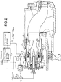
- This type of two-stage combustion apparatus comprises an antechamber (diffusion combustion chamber) l, F1 nozzles 2 for diffusion combustion, a main chamber (premix combustion chamber) 3, F2 nozzles 4 for premix combustion, and a combustion air supply section.
- a combustion air supply section Particularly, in order to control the flow rate of premixed air A2 through the F2 nozzles 4 the stable combustion range of which is narrow, an internal flow rate control (referred to as IFC, hereinafter) 5 is provided in this combustion air supply section.
- IFC internal flow rate control
- the fuel-air ratio (the ratio of fuel amount to air amount) be controlled to be kept at a constant value by changing the air flow rate in response to the fuel flow rate determined beforehand for the operation of the gas turbine as disclosed in Japanese Patent unexamined Publication No. 60-66020 as well. Namely, the fuel flow rate is changed in accordance with the change of load and the distribution of air in the burners is also changed in accordance with the change of this fuel flow rate so as to set the fuel-to-air ratio at the predetermined value, thereby realizing the stabilization of the combustion and the reduction of the NOx.
- Figure 3 shows the relationship between the fuel-air ratio and the NOx, in which the abscissa represents the fuel-air ratio and the ordinate represents the NOx relative value and which illustrates the difference between the diffusion combustion and the premix combustion.
- the theoretical fuel-air ratio of methane is 0.058, and gas turbine burners are usually used at fuel-air ratios smaller than 0.058.
- the diffusion combustion which is stable over the wide operation range is utilized from the start-up to the low-load operation of the gas turbine, and the premix combustion and the diffusion combustion are utilized simultaneously from the low-load operation to the rated-load operation, so as to reduce the NOx.
- the fuel-air ratio is set to be in the operation range by controlling the flow rate of air A2 by the IFC 5 of Figure 2.
- Total combustion air A of Figure 2 is divided into a flow rate of air A1 flowing through the antechamber 1, a flow rate of air A2 flowing through the main chamber 3 and a flow rate of air A3 flowing into through dilution holes 6.
- BOG gas blow-off gas
- the calorie of the BOG gas is lower than that of the LNG due to the difference in boiling points of the fuel components. If the BOG gas is not discharged to the outside periodically, the internal pressure of an LNG tank is increased to bring about damage. To cope with this, the BOG gas is treated as being mixed with the LNG in the existing circumstances. This results in a sudden change of the calorific value (calorie) in the LNG power plant. It is therefore difficult to realize the stable combustion and the reduction of the NOx by controlling the fuel flow alone in the conventional manner.
- An object of the present invention is to solve the above-described problems, and further, to provide a combustion apparatus capable of dealing with various kinds of fuel.
- the abscissa represents the fuel command signal correspondingly to the load ranging from the no load to the rated load and the ordinate represents the flow rate of fuel through the F1 and F2 nozzles 2 and 4 and the opening of the IFC 5.
- the flow rate of fuel is small and a lean combustion is effected, so that the diffusion combustion is utilized only due to the F1 nozzles 2.
- the IFC 5 is fully opened to reduce the air in the antechamber 1 so that the fuel-air ratio is increased to realize the stable combustion.
- the opening of the IFC 5 is increased, as the load is increased to the rated load in due order through A ⁇ B ⁇ C, so that the flow rate of air A2 through the main chamber 3 is increased and, at the same time, the fuel supplied from the F2 nozzles 4 is increased, thereby setting the fuel-air ratio to be in the operation range shown in Figure 3 so as to reduce the NOx.
- the fuel command signal is sent to an IFC opening setting device 7 so as to operate an IFC driving device 8 as shown in Figure 2.
- the composition or calorific value of the fuel is measured before it is supplied to the burners and the air distribution is changed so as to minimize the NOx in the premix combustion zone within the stable range, and the change of the load attributable to the change of the calorific value is controlled by the supply of the fuel to the diffusion combustion zone.
- the amount of air bypassed is so set as to minimize the NOx in the premix combustion zone in accordance with the change of the calorific value, the change of the load attributable to the change of the calorific value is controlled by the supply of the fuel to the diffusion combustion zone.
- the calorific value of the fuel is measured by a means or device for measuring the calorific value before the fuel flows into gas turbine burners. Further, a means or device for regulating the air flow rate distribution of the burners operates to change the distribution of air in accordance with the change of the flow rate of the design fuel so as to keep the fuel-air ratio at the design value. It is noted that the fuel is designed to be used in several conditions classified taking the calorific value as the parameter so as to control the flow rate of air to be changed in accordance with the measured calorific value while keeping the flow rate of the fuel constant.
- the same amount of the fuel as that supplied before the calorific value is changed is supplied to the premix combustion zone and the flow of the fuel supplied to the diffusion combustion zone is changed so as to increase/decrease the fuel used to correct the change of the load.
- the calorific value is decreased the amount of the fuel supplied is increased, and when the calorific value is increased the amount of the fuel supplied is decreased, thereby keeping the load constant.
- fuel is sampled on the upstream side of an F1 fuel control valve 12 and an F2 fuel control valve 13 and its calorific value is measured by a calorific value measuring device 9.
- Deviation from the design value is sent from the measuring device 9 to an IFC opening correcting device 10.
- a signal from the IFC opening correcting device 10 and a signal issued from an IFC opening setting device 7 based on the fuel control command are added by an adder 11 in which the fuel signal is corrected for the calorific value.
- an IFC driving device 8 is operated to open/close an IFC 5 so as to set the ratio of air A2 to the fuel through F2 fuel nozzles 2 at a target value.
- the signal from the calorific value measuring device 9 is also sent to a fuel distribution correcting device 17 so that the flow of fuel used for correcting increase/decrease of the output attributable to the change of the calorific value is so controlled as to be distributed only to the F1 nozzles 2 for the diffusion combustion, while the flow rate of the fuel F2 makes no contribution to the correction for the power.
- Figure 5 shows the relationship between the calorific value and the concentration of the NOx taking the IFC opening as a parameter, in which the abscissa represents the calorific value of the fuel and the ordinate represents the concentration of the NOx.
- the calorific value is changed at the design point during the operation, if only the flow rate of the fuel is controlled as conventionally done, the calorific value reaches the premix flame blowout limit when it is not greater than the minimum value because the IFC opening is not changed, resulting in a flame-out.
- the calorific value is increased, the NOx content is increased.
- the calorific value is further increased to reach the maximum, it exceeds the premix flame backfire limit so as to cause a backfire, resulting in the possibility of the burnout of the F2 nozzle 2.
- the IFC opening is shifted from the design IFC opening to the smaller side until it is set at A, thereby preventing the blowout.
- the calorific value is increased, the IFC opening is shifted to the larger side until it is set at B, thereby keeping the NOx content low as well as preventing the backfire.
- the abscissa represents the fuel command signal and the ordinate represents the IFC opening.
- the IFC opening is increased/decreased based on the measured value of the change of the calorific value.
- the IFC opening is controlled to be in the range of +K A to -K A as shown at A on the abscissa of Figure 6.
- the amount of correction for the flow of air required becomes larger even for the same change of the calorific value, and therefore, the amount of correction is increased as being in the range of +K B to -K B at B on the abscissa and in the range of +K C to -K C at C on the abscissa.
- Figure 10 shows the relationship between the power and the flow rate of fuel taking the calorific value as a parameter, in which the abscissa represents the power and the ordinate represents the flow rates of fuels F1 and F2.
- the fuel increased to control the change of the power attributable to the change of the calorific value is used for the stable F1 diffusion combustion alone, while for the F2 premix combustion, only the flow rate of air is changed at once when the calorific value is changed, thereby setting the fuel-air ratio properly at which the stable and low NOx combustion can be effected.
- Figure 9 shows the effect of this controlling method, in which the abscissa represents the fuel-air ratio and the ordinate represents the NOx relative value.
- the IFC 5 of Figure 1 is changed to the close position so as to reduce the flow of air A2 and increase the flow of air A1.
- the F2 premix combustion is shifted to the point E at which the stable and low NOx combustion can be effected.
- the F1 diffusion combustion is shifted, in correspondence to the increase of the air A1, from the point D to the point E which is nearer to the unstable range, and however, there arises no problem because the range of the stable fuel-air ratios is wider as compared with the F2 premix combustion.
- the amount of the fuel corresponding to the shortage required for keeping the power constant is appropriated for the F1 diffusion combustion zone, it is shifted from the point E to the point E' at which a more stable combustion can be effected.
- the abscissa represents the calorific value signal and the ordinate represents the IFC opening correction amount.
- the range of the fuel command signal is taken as parameter that is so set as being 1 between the points A and B, 2 between the points B and C and 3 between the point C and the point of the rated load, as shown in Figure 6, while giving consideration to the increase of the sensitivity in the amount of correction for the flow rate of air attributable to the increase of the flow rate of the fuel.
- FIG 8 is a control block diagram of the present invention.
- the IFC opening setting device 7 is the conventional setting device of Figure 4 and the IFC opening correcting device 10 is the one shown in Figure 7.
- the signal is sent to the adder 11 through a rate limit 14 provided additionally.
- the signal is passed through a limiter 15 before it serves as the IFC control signal so as to protect the issue of such command that is beyond the IFC full open position.
- the present invention it is possible to prevent the blowout and backfire of the premix flame, increase of the NOx concentration and the like which are caused due to the change of the calorific value of the fuel, and it is also possible to improve the reliability on the treatment of BOG gas in the LNG firing combined cycle power plant.
Abstract
Description
- This invention relates to improvements in combustion apparatus and controlling method therefore, and particularly it relates to a combustion apparatus suitable for application to a gas turbine and comprising a premix burner and a diffusion burner.
- Conventional combustion apparatus applied generally to the gas turbine has been usually equipped with a diffusion burner C₁ at the head thereof and with a premix burner C₂ downstream of this diffusion burner as shown in Figure 2.
- Thus, the burners have been combined in two stages for the purpose of obtaining a combustion apparatus capable of effecting a low NOx and stable combustion due to the diffusion combustion which achieves a high combustion stability and the premix combustion which achieves a high reduction of NOx concentration although the stable combustion range therein is narrow.
- This type of two-stage combustion apparatus comprises an antechamber (diffusion combustion chamber) l,
F₁ nozzles 2 for diffusion combustion, a main chamber (premix combustion chamber) 3,F₂ nozzles 4 for premix combustion, and a combustion air supply section. Particularly, in order to control the flow rate of premixed air A₂ through theF₂ nozzles 4 the stable combustion range of which is narrow, an internal flow rate control (referred to as IFC, hereinafter) 5 is provided in this combustion air supply section. - In the combustion apparatus having such construction, it has been the main current that the fuel-air ratio (the ratio of fuel amount to air amount) be controlled to be kept at a constant value by changing the air flow rate in response to the fuel flow rate determined beforehand for the operation of the gas turbine as disclosed in Japanese Patent unexamined Publication No. 60-66020 as well. Namely, the fuel flow rate is changed in accordance with the change of load and the distribution of air in the burners is also changed in accordance with the change of this fuel flow rate so as to set the fuel-to-air ratio at the predetermined value, thereby realizing the stabilization of the combustion and the reduction of the NOx.
- Figure 3 shows the relationship between the fuel-air ratio and the NOx, in which the abscissa represents the fuel-air ratio and the ordinate represents the NOx relative value and which illustrates the difference between the diffusion combustion and the premix combustion. The theoretical fuel-air ratio of methane is 0.058, and gas turbine burners are usually used at fuel-air ratios smaller than 0.058. In operation, the diffusion combustion which is stable over the wide operation range is utilized from the start-up to the low-load operation of the gas turbine, and the premix combustion and the diffusion combustion are utilized simultaneously from the low-load operation to the rated-load operation, so as to reduce the NOx. On that occasion, since the range of the fuel-air ratio in which the premix combustion is effected completely (operation range of F₂) is narrow, the fuel-air ratio is set to be in the operation range by controlling the flow rate of air A₂ by the
IFC 5 of Figure 2. Total combustion air A of Figure 2 is divided into a flow rate of air A₁ flowing through the antechamber 1, a flow rate of air A₂ flowing through themain chamber 3 and a flow rate of air A₃ flowing into through dilution holes 6. When the IFC 5 is opened, the amount of air A₂ is increased and the amounts of airs A₁ and A₃ are decreased, while when it is closed, the amount of air A₂ is decreased and the amounts of airs A₁ and A₃ are increased. - From the viewpoint of efficient use of energy, there arises a problem of the treatment of vaporized gas called BOG gas (boil-off gas) generated in power generation using LNG. The calorie of the BOG gas is lower than that of the LNG due to the difference in boiling points of the fuel components. If the BOG gas is not discharged to the outside periodically, the internal pressure of an LNG tank is increased to bring about damage. To cope with this, the BOG gas is treated as being mixed with the LNG in the existing circumstances. This results in a sudden change of the calorific value (calorie) in the LNG power plant. It is therefore difficult to realize the stable combustion and the reduction of the NOx by controlling the fuel flow alone in the conventional manner.
- In the above-described prior art, change of the fuel flow rate due to load change has been taken into consideration, and however, change of the fuel characteristics such as the calorific value has not been taken into consideration. Therefore, in case of effecting the lean premix combustion and the two-stage combustion including the diffusion combustion and the premix combustion with the low NOx burner or the like, if the calorific value is changed during the constant fuel flow operation, flame is made unstable so as to cause a flame-out, or conversely a backfire of premix flame, increase of the NOx and the like. Further, this gives rise to a problem that if the calorific value of the supplied fuel is changed drastically during the constant fuel flow rate operation or the constant load operation, the load is changed greatly. Change of the calorific value of the fuel is the problem caused at the time of treating a low-calorie gas called BOG gas (boil-off gas), which is vaporized to above the LNG, in the LNG (liquefied natural gas) plant.
- An object of the present invention is to solve the above-described problems, and further, to provide a combustion apparatus capable of dealing with various kinds of fuel.
- For this reason, in order to realize a stable combustion over the wide range from no-load operation to the rated-load operation, such control as shown in Figure 4 has been performed. In this diagram, the abscissa represents the fuel command signal correspondingly to the load ranging from the no load to the rated load and the ordinate represents the flow rate of fuel through the F₁ and
F₂ nozzles IFC 5. On the lower load side, the flow rate of fuel is small and a lean combustion is effected, so that the diffusion combustion is utilized only due to the F₁nozzles 2. The IFC 5 is fully opened to reduce the air in the antechamber 1 so that the fuel-air ratio is increased to realize the stable combustion. It is necessary to reduce the ignition load of theF₂ nozzles 4 for the purpose of expanding the range of the operation load. Therefore, by closing theIFC 5 from the point 1 to thepoint 2 as shown in Figure 4, the flow rate of air A₂ through themain chamber 3 is reduced so that the combustion can be effected in a stabilized manner with the fuel supplied from theF₂ nozzles 4 at the time of changing over the fuel. At that time, the flow rate of air A₁ through the antechamber 1 is increased so far as the combustion can be effected in a stabilized manner with the flow rate of the fuel flowing through theF₁ nozzles 2 at the time of the changing-over, and the load at that time is regarded as the minimum change-over load. - After the ignition at the
F₂ nozzles 4, the opening of theIFC 5 is increased, as the load is increased to the rated load in due order through A → B → C, so that the flow rate of air A₂ through themain chamber 3 is increased and, at the same time, the fuel supplied from theF₂ nozzles 4 is increased, thereby setting the fuel-air ratio to be in the operation range shown in Figure 3 so as to reduce the NOx. - In controlling the fuel, the fuel command signal is sent to an IFC
opening setting device 7 so as to operate anIFC driving device 8 as shown in Figure 2. - To this end, in case of distributing the diffusion combustion air and the premix combustion air, the composition or calorific value of the fuel is measured before it is supplied to the burners and the air distribution is changed so as to minimize the NOx in the premix combustion zone within the stable range, and the change of the load attributable to the change of the calorific value is controlled by the supply of the fuel to the diffusion combustion zone.
- Further, in case of controlling the fuel-air ratio by making the combustion air bypass to downstream of the burner outlet, the amount of air bypassed is so set as to minimize the NOx in the premix combustion zone in accordance with the change of the calorific value, the change of the load attributable to the change of the calorific value is controlled by the supply of the fuel to the diffusion combustion zone.
- The calorific value of the fuel is measured by a means or device for measuring the calorific value before the fuel flows into gas turbine burners. Further, a means or device for regulating the air flow rate distribution of the burners operates to change the distribution of air in accordance with the change of the flow rate of the design fuel so as to keep the fuel-air ratio at the design value. It is noted that the fuel is designed to be used in several conditions classified taking the calorific value as the parameter so as to control the flow rate of air to be changed in accordance with the measured calorific value while keeping the flow rate of the fuel constant.
- Namely, when the calorific value is changed to be decreased from its central value, the flow of air is decreased. To the contrary, when the calorific value is changed to be increased, the flow of air is increased.
- In controlling the distribution of the fuel, the same amount of the fuel as that supplied before the calorific value is changed is supplied to the premix combustion zone and the flow of the fuel supplied to the diffusion combustion zone is changed so as to increase/decrease the fuel used to correct the change of the load. When the calorific value is decreased the amount of the fuel supplied is increased, and when the calorific value is increased the amount of the fuel supplied is decreased, thereby keeping the load constant.
- The foregoing and other objects, features as well as advantages of the invention will be made clearer from the description hereafter of a preferred embodiment referring to the drawings.
-
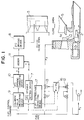
- Figure 1 is a diagrammatic view showing essential portions of a combustion apparatus according to a preferred embodiment of the present invention;
- Figure 2 is a vertically sectional side view of a conventional combustion apparatus;
- Figure 3 is a graph showing the relationship between the NOx and the fuel-air ratio of the combustion apparatus;
- Figure 4 is a graph showing the relationship between the fuel command signal and the flow rate of fuel as well as the flow rate of air in the conventional combustion apparatus;
- Figure 5 is a graph showing characteristic relationship between the calorific value and the NOx contained in the combustion;
- Figure 6 is a graph showing characteristic relationship between the fuel command signal and the flow rate of air in the combustion apparatus according to the preferred embodiment of the present invention;
- Figure 7 is a diagram showing the relationship between the IFC opening correction amount and the calorific value signal;
- Figure 8 is a block diagram for explanation of the operation of the combustion apparatus according to the preferred embodiment of the present invention;
- Figure 9 is an illustration showing the relationship between the fuel-air ratio and the NOx in the combustion apparatus according to the preferred embodiment of the present invention; and
- Figure 10 is an illustration showing the relationship between the power and the fuel distribution in the combustion apparatus according to the preferred embodiment of the present invention.
- Description will be given below of an embodiment of the present invention with reference to Figure 1.
- In the present embodiment, fuel is sampled on the upstream side of an F₁
fuel control valve 12 and an F₂fuel control valve 13 and its calorific value is measured by a calorificvalue measuring device 9. Deviation from the design value is sent from themeasuring device 9 to an IFC opening correcting device 10. A signal from the IFC opening correcting device 10 and a signal issued from an IFCopening setting device 7 based on the fuel control command are added by an adder 11 in which the fuel signal is corrected for the calorific value. Then, an IFCdriving device 8 is operated to open/close an IFC 5 so as to set the ratio of air A₂ to the fuel throughF₂ fuel nozzles 2 at a target value. - On the other hand, the signal from the calorific
value measuring device 9 is also sent to a fueldistribution correcting device 17 so that the flow of fuel used for correcting increase/decrease of the output attributable to the change of the calorific value is so controlled as to be distributed only to the F₁nozzles 2 for the diffusion combustion, while the flow rate of the fuel F₂ makes no contribution to the correction for the power. - Figure 5 shows the relationship between the calorific value and the concentration of the NOx taking the IFC opening as a parameter, in which the abscissa represents the calorific value of the fuel and the ordinate represents the concentration of the NOx. In case that the calorific value is changed at the design point during the operation, if only the flow rate of the fuel is controlled as conventionally done, the calorific value reaches the premix flame blowout limit when it is not greater than the minimum value because the IFC opening is not changed, resulting in a flame-out. To the contrary, in case that the calorific value is increased, the NOx content is increased. When the calorific value is further increased to reach the maximum, it exceeds the premix flame backfire limit so as to cause a backfire, resulting in the possibility of the burnout of the
F₂ nozzle 2. - According to the present invention, when the calorific value is shifted to the lower value, the IFC opening is shifted from the design IFC opening to the smaller side until it is set at A, thereby preventing the blowout. To the contrary, when the calorific value is increased, the IFC opening is shifted to the larger side until it is set at B, thereby keeping the NOx content low as well as preventing the backfire.
- In Figure 6, the abscissa represents the fuel command signal and the ordinate represents the IFC opening. For the same fuel command signal, the IFC opening is increased/decreased based on the measured value of the change of the calorific value. On the lower load side, since the flow rate of the fuel is small, the amount of correction for the flow rate of air attributable to the change of the calorific value is also small. In consequence, the IFC opening is controlled to be in the range of +KA to -KA as shown at A on the abscissa of Figure 6. As the load is increased and hence the flow rate of the fuel is increased, the amount of correction for the flow of air required becomes larger even for the same change of the calorific value, and therefore, the amount of correction is increased as being in the range of +KB to -KB at B on the abscissa and in the range of +KC to -KC at C on the abscissa.
- Figure 10 shows the relationship between the power and the flow rate of fuel taking the calorific value as a parameter, in which the abscissa represents the power and the ordinate represents the flow rates of fuels F₁ and F₂. When the calorific value is reduced at the time of 100% power, the power is reduced from the design point A to a point D. When it is intended to operate at constant power, it is necessary to increase the fuel by an amount corresponding to the reduction of the calorific value so as to reach a point E. According to the present invention, when this is the case, the fuel increased to control the change of the power attributable to the change of the calorific value is used for the stable F₁ diffusion combustion alone, while for the F₂ premix combustion, only the flow rate of air is changed at once when the calorific value is changed, thereby setting the fuel-air ratio properly at which the stable and low NOx combustion can be effected. Figure 9 shows the effect of this controlling method, in which the abscissa represents the fuel-air ratio and the ordinate represents the NOx relative value. In case that the calorific value of the fuel is reduced during the operation at the design point A, since the F₁, F₂ NOx is shifted to the point D in this control, the
IFC 5 of Figure 1 is changed to the close position so as to reduce the flow of air A₂ and increase the flow of air A₁. As shown in Figure 9, the F₂ premix combustion is shifted to the point E at which the stable and low NOx combustion can be effected. The F₁ diffusion combustion is shifted, in correspondence to the increase of the air A₁, from the point D to the point E which is nearer to the unstable range, and however, there arises no problem because the range of the stable fuel-air ratios is wider as compared with the F₂ premix combustion. Further, since the amount of the fuel corresponding to the shortage required for keeping the power constant is appropriated for the F₁ diffusion combustion zone, it is shifted from the point E to the point E' at which a more stable combustion can be effected. - In the way described above, it is possible to realize a stable and low NOx combustion even when the calorific value is changed.
- In Figure 7, the abscissa represents the calorific value signal and the ordinate represents the IFC opening correction amount. The range of the fuel command signal is taken as parameter that is so set as being 1 between the points A and B, 2 between the points B and C and 3 between the point C and the point of the rated load, as shown in Figure 6, while giving consideration to the increase of the sensitivity in the amount of correction for the flow rate of air attributable to the increase of the flow rate of the fuel.
- Figure 8 is a control block diagram of the present invention. The IFC
opening setting device 7 is the conventional setting device of Figure 4 and the IFC opening correcting device 10 is the one shown in Figure 7. In order to limit the IFC opening/closing speed, the signal is sent to the adder 11 through arate limit 14 provided additionally. The signal is passed through a limiter 15 before it serves as the IFC control signal so as to protect the issue of such command that is beyond the IFC full open position. - According to the present invention, it is possible to prevent the blowout and backfire of the premix flame, increase of the NOx concentration and the like which are caused due to the change of the calorific value of the fuel, and it is also possible to improve the reliability on the treatment of BOG gas in the LNG firing combined cycle power plant.
Claims (11)
- A method for controlling a combustion apparatus which has a premix burner and a diffusion burner, said method comprising the steps of:
controlling an amount of air supplied to the premix burner in accordance with a calorie of fuel to be supplied to said apparatus so as to achieve a low NOx within a range in which the premix burner effects a stable combustion; and
supplementing a change of a power of the combustion apparatus attributable to the control of the amount of air supplied to the premix burner by controlling an amount of the fuel supplied to the diffusion burner. - A method for controlling a combustion apparatus which has a premix burner and a diffusion burner, said method comprising the steps of:
controlling, when a calorie of fuel to be supplied to the premix burner is changed, an amount of air supplied to the premix burner in accordance with the amount of change of the calorie so as to achieve a low NOx within a range of stable combustion; and
supplementing a change of a power of the combustion apparatus attributable to the change of the calorie of the fuel by controlling an amount of the fuel supplied to the diffusion burner. - A method for controlling a combustion apparatus which has a premix burner and a diffusion burner which are both supplied with fuel from a same fuel supply system, said method comprising the steps of:
controlling, when a calorie of the fuel supplied is changed, a fuel-air ratio in the premix burner in accordance with the amount of change of the calorie so as to achieve a low NOx within a range in which the premix burner effects a stable combustion; and
supplementing a change of a power of the combustion apparatus attributable to the change of the calorie of the fuel by controlling an amount of the fuel supplied to the diffusion burner. - A method for controlling a combustion apparatus which has a premix burner and a diffusion burner which are both supplied with fuel from a same fuel supply system, said method comprising the steps of:
monitoring a calorific value possessed by the fuel;
controlling a fuel-air ratio of the premix burner in response to a detection of a change of the calorific value during the monitoring so as to allow the premix burner to effect a combustion within a range of stable combustion; and
supplementing a change of a power of the combustion apparatus attributable to the change of the calorific value of the fuel by controlling an amount of the fuel supplied to the diffusion burner. - A method for controlling a combustion apparatus which comprises a premix burner and a diffusion burner both of which effect combustion of same kind of fuel, said method comprising the steps of:
monitoring a calorific value possessed by the fuel;
controlling, when it is detected by this monitoring that the fuel supplied possesses a different calorific value, a fuel-air ratio of the premix burner in accordance with the change of the calorific value so as to be in a range in which the combustion is effected in a stabilized manner while achieving a low NOx; and
supplementing a change of a power of the combustion apparatus attributable to the change of the calorific value of the fuel by controlling an amount of the fuel supplied to the diffusion burner. - A method for controlling a combustion apparatus which has a premix burner and a diffusion burner both of which effect combustion of same kind of fuel, said method comprising the steps of:
monitoring a calorific value possessed by the fuel;
controlling, when it is detected by this monitoring that the fuel supplied possesses a different calorific value, an amount of air supplied to the premix burner in accordance with the change of the calorific value so as to allow the premix burner to effect a stable combustion while achieving a low NOx; and
supplementing a change of a power of the combustion apparatus attributable to the change of the calorific value of the fuel by controlling an amount of the fuel supplied to the diffusion burner. - A method for controlling a combustion apparatus which has a premix burner and a diffusion burner which are both supplied with fuel from a same fuel supply system with amounts of fuel and air supplied thereto being controlled in accordance with a load of the combustion apparatus, said method comprising the steps of:
monitoring a calorific value possessed by the fuel;
controlling, when it is detected by this monitoring that the fuel supplied possesses a different calorific value, an amount of air supplied to the premix burner in accordance with the change of the calorific value so as to allow the premix burner to effect a stable combustion while achieving a low NOx; and
supplementing a change of a power of the combustion apparatus attributable to the change of the calorific value of the fuel by controlling an amount of the fuel supplied to the diffusion burner. - A method for controlling a combustion apparatus which has a premix burner and a diffusion burner, said method comprising the steps of:
controlling, when a calorie of fuel to be supplied to the premix burner is changed, an amount of air supplied to the premix burner so as to allow the premix burner to effect a low NOx combustion within a range of stable combustion; and
supplementing a change of a power of the combustion apparatus attributable to the change of the calorie of the fuel by controlling an amount of the fuel supplied to the diffusion burner. - A combustion apparatus which has a premix burner and a diffusion burner, said apparatus comprising:
a calorific value measuring device for measuring a calorific value of fuel to be supplied to the combustion apparatus;
a control device for controlling an amount of air supplied to the premix burner in accordance with a detection value of the calorific value measuring device so as to allow the premix burner to effect a low NOx combustion within a range of stable combustion; and
another control device for controlling an amount of fuel supplied to the diffusion burner so as to supplement a change of a power of the combustion apparatus attributable to the change of said calorific value. - A combustion apparatus which has a diffusion burner and a premix burner and in which an air supply regulating device for regulating an amount of air supplied is provided in an air supply system for the premix burner, said apparatus comprising:
a fuel composition monitoring device provided in a fuel supply system for the premix burner for measuring a calorific value possessed by a fuel supplied and for issuing a command signal in accordance with the calorific value thus measured;
a control device disposed in the air supply regulating device of the premix burner for receiving the command signal and controlling in accordance with this command signal the air supply regulating device so as to determine an amount of air supplied that allows the premix burner to effect combustion within a stable range while achieving a low NOx; and
a fuel control device disposed in a fuel supply system for the diffusion burner for controlling fuel to be supplied to the diffusion burner so as to supplement a change of a power of the combustion apparatus attributable to the change of the calorific value. - A combustion apparatus which has a diffusion burner and a premix burner and in which an air supply regulating device for regulating an amount of air supplied is provided in an air supply system for the premix burner, said apparatus comprising:
a fuel composition monitoring device provided in a fuel supply system for the premix burner for measuring a calorie possessed by a fuel supplied and issue a signal corresponding to the calorie thus measured;
a control device disposed in the air supply regulating device for the premix burner for receiving the signal and for controlling in accordance with this signal the air supply regulating device so as to determine an amount of air supplied that allows the premix burner to effect combustion within a stable range while achieving a low NOx; and
a fuel control device disposed in a fuel supply system for the diffusion burner for controlling a fuel supplied so as to supplement a change of a power of the combustion apparatus attributable to the change of the calorie.
Applications Claiming Priority (2)
| Application Number | Priority Date | Filing Date | Title |
|---|---|---|---|
| JP30655/91 | 1991-02-26 | ||
| JP3030655A JP2961913B2 (en) | 1991-02-26 | 1991-02-26 | Combustion device and control method thereof |
Publications (2)
| Publication Number | Publication Date |
|---|---|
| EP0501313A1 true EP0501313A1 (en) | 1992-09-02 |
| EP0501313B1 EP0501313B1 (en) | 1997-01-29 |
Family
ID=12309794
Family Applications (1)
| Application Number | Title | Priority Date | Filing Date |
|---|---|---|---|
| EP92102875A Expired - Lifetime EP0501313B1 (en) | 1991-02-26 | 1992-02-20 | Combustion apparatus and control method therefor |
Country Status (4)
| Country | Link |
|---|---|
| US (1) | US5281129A (en) |
| EP (1) | EP0501313B1 (en) |
| JP (1) | JP2961913B2 (en) |
| DE (1) | DE69217093T2 (en) |
Cited By (8)
| Publication number | Priority date | Publication date | Assignee | Title |
|---|---|---|---|---|
| WO1996000364A1 (en) * | 1994-06-24 | 1996-01-04 | United Technologies Corporation | Pilot injector for gas turbine engines |
| EP0915242A3 (en) * | 1997-11-04 | 2001-02-21 | Hitachi, Ltd. | Gas turbine |
| EP1174606A2 (en) * | 2000-07-21 | 2002-01-23 | Mitsubishi Heavy Industries, Ltd. | Method of controlling a gas turbine plant |
| EP1524423A1 (en) * | 2003-10-13 | 2005-04-20 | Siemens Aktiengesellschaft | Method and device for levelling out the fluctuation of fuel composition in a gas turbine |
| WO2008092252A1 (en) * | 2007-01-30 | 2008-08-07 | Pratt & Whitney Canada Corp. | Gas turbine engine fuel control system |
| RU2482393C2 (en) * | 2007-05-23 | 2013-05-20 | Нуово Пиньоне С.п.А. | Method and device to control combustion in gas turbine |
| EP1703102A3 (en) * | 2005-02-23 | 2015-02-18 | Kabushiki Kaisha Toshiba | Liquefied natural gas power plant and operation method thereof |
| EP1788309A3 (en) * | 2005-11-22 | 2015-06-03 | General Electric Company | Methods and apparatus for operating gas turbine engine systems |
Families Citing this family (10)
| Publication number | Priority date | Publication date | Assignee | Title |
|---|---|---|---|---|
| US5987875A (en) * | 1997-07-14 | 1999-11-23 | Siemens Westinghouse Power Corporation | Pilot nozzle steam injection for reduced NOx emissions, and method |
| EP1112461B1 (en) * | 1998-09-10 | 2004-04-14 | Siemens Aktiengesellschaft | Method for operating a burner and burner arrangement |
| US6250063B1 (en) * | 1999-08-19 | 2001-06-26 | General Electric Co. | Fuel staging apparatus and methods for gas turbine nozzles |
| JP4495971B2 (en) * | 2002-01-25 | 2010-07-07 | アルストム テクノロジー リミテッド | Method for operating a gas turbine group |
| JP4563242B2 (en) * | 2005-04-19 | 2010-10-13 | 三菱重工業株式会社 | Fuel gas calorie control method and apparatus |
| JP4745940B2 (en) * | 2006-11-09 | 2011-08-10 | 三菱重工業株式会社 | Coal gasification combined power generation system and operation control method thereof |
| US8151740B2 (en) * | 2009-06-02 | 2012-04-10 | General Electric Company | System and method for controlling the calorie content of a fuel |
| JP5159741B2 (en) * | 2009-09-30 | 2013-03-13 | 株式会社日立製作所 | Control device for gas turbine combustor and control method for gas turbine combustor |
| JP6190670B2 (en) * | 2013-08-30 | 2017-08-30 | 三菱日立パワーシステムズ株式会社 | Gas turbine combustion system |
| US10281140B2 (en) | 2014-07-15 | 2019-05-07 | Chevron U.S.A. Inc. | Low NOx combustion method and apparatus |
Citations (4)
| Publication number | Priority date | Publication date | Assignee | Title |
|---|---|---|---|---|
| US3766734A (en) * | 1972-03-01 | 1973-10-23 | Gen Electric | Dual fuel control system for a gas turbine |
| EP0055852A1 (en) * | 1980-12-27 | 1982-07-14 | Hitachi, Ltd. | Method and apparatus for controlling combustion of gasified fuel |
| EP0222173A1 (en) * | 1985-10-11 | 1987-05-20 | Hitachi, Ltd. | Combustor for gas turbine |
| WO1988008075A1 (en) * | 1987-04-09 | 1988-10-20 | Solar Turbines Incorporated | Wide range gaseous fuel combustion system for gas turbine engines |
Family Cites Families (10)
| Publication number | Priority date | Publication date | Assignee | Title |
|---|---|---|---|---|
| US4111637A (en) * | 1977-03-10 | 1978-09-05 | Phillips Petroleum Company | Control system for plurality of gas supplies |
| US4369026A (en) * | 1980-02-21 | 1983-01-18 | Phillips Petroleum Company | Control of the fuel/oxygen ratio for a combustion process |
| IT1131905B (en) * | 1980-07-04 | 1986-06-25 | Snam Spa | METHOD FOR REGULATING THE THERMAL FLOW RATE OF A NATURAL GAS-POWERED SYSTEM WITH VARIABLE POWER AND DENSITY AND APPARATUS SUITABLE FOR THE PURPOSE |
| US4815965A (en) * | 1983-05-12 | 1989-03-28 | Applied Automation, Inc. | Monitoring and control of a furnace |
| JPS6066020A (en) * | 1983-09-21 | 1985-04-16 | Hitachi Ltd | Control method of air for combustion apparatus |
| DE3408397A1 (en) * | 1984-03-08 | 1985-09-19 | Ruhrgas Ag, 4300 Essen | METHOD AND ARRANGEMENT FOR DETERMINING THE MIXING RATIO OF A MIXTURE CONTAINING OXYGEN CARRIER GAS AND A FUEL |
| JPS6140432A (en) * | 1984-08-01 | 1986-02-26 | Hitachi Ltd | Fuel control device in gas turbine |
| JPS63194111A (en) * | 1987-02-06 | 1988-08-11 | Hitachi Ltd | Combustion method for gas fuel and equipment thereof |
| JPH0674892B2 (en) * | 1987-06-10 | 1994-09-21 | 株式会社日立製作所 | Combustion control method and apparatus for multi-stage combustor |
| JPH0653023B2 (en) * | 1987-08-12 | 1994-07-20 | 株式会社クボタ | The second reducing device of the thresher |
-
1991
- 1991-02-26 JP JP3030655A patent/JP2961913B2/en not_active Expired - Lifetime
-
1992
- 1992-02-20 DE DE69217093T patent/DE69217093T2/en not_active Expired - Lifetime
- 1992-02-20 EP EP92102875A patent/EP0501313B1/en not_active Expired - Lifetime
- 1992-02-25 US US07/840,813 patent/US5281129A/en not_active Expired - Lifetime
Patent Citations (4)
| Publication number | Priority date | Publication date | Assignee | Title |
|---|---|---|---|---|
| US3766734A (en) * | 1972-03-01 | 1973-10-23 | Gen Electric | Dual fuel control system for a gas turbine |
| EP0055852A1 (en) * | 1980-12-27 | 1982-07-14 | Hitachi, Ltd. | Method and apparatus for controlling combustion of gasified fuel |
| EP0222173A1 (en) * | 1985-10-11 | 1987-05-20 | Hitachi, Ltd. | Combustor for gas turbine |
| WO1988008075A1 (en) * | 1987-04-09 | 1988-10-20 | Solar Turbines Incorporated | Wide range gaseous fuel combustion system for gas turbine engines |
Cited By (15)
| Publication number | Priority date | Publication date | Assignee | Title |
|---|---|---|---|---|
| WO1996000364A1 (en) * | 1994-06-24 | 1996-01-04 | United Technologies Corporation | Pilot injector for gas turbine engines |
| US5755090A (en) * | 1994-06-24 | 1998-05-26 | United Technologies Corporation | Pilot injector for gas turbine engines |
| EP0915242A3 (en) * | 1997-11-04 | 2001-02-21 | Hitachi, Ltd. | Gas turbine |
| EP1174606A3 (en) * | 2000-07-21 | 2006-04-19 | Mitsubishi Heavy Industries, Ltd. | Method of controlling a gas turbine plant |
| EP1174606A2 (en) * | 2000-07-21 | 2002-01-23 | Mitsubishi Heavy Industries, Ltd. | Method of controlling a gas turbine plant |
| EP1524423A1 (en) * | 2003-10-13 | 2005-04-20 | Siemens Aktiengesellschaft | Method and device for levelling out the fluctuation of fuel composition in a gas turbine |
| WO2005038214A1 (en) * | 2003-10-13 | 2005-04-28 | Siemens Aktiengesellschaft | Method and device for compensating variations in fuel composition in a gas turbine system |
| US7472540B2 (en) | 2003-10-13 | 2009-01-06 | Siemens Aktiengesellschaft | Method and device for compensating variations in fuel composition in a gas turbine system |
| EP1703102A3 (en) * | 2005-02-23 | 2015-02-18 | Kabushiki Kaisha Toshiba | Liquefied natural gas power plant and operation method thereof |
| EP1788309A3 (en) * | 2005-11-22 | 2015-06-03 | General Electric Company | Methods and apparatus for operating gas turbine engine systems |
| WO2008092252A1 (en) * | 2007-01-30 | 2008-08-07 | Pratt & Whitney Canada Corp. | Gas turbine engine fuel control system |
| US7950216B2 (en) | 2007-01-30 | 2011-05-31 | Pratt & Whitney Canada Corp. | Gas turbine engine fuel control system |
| US9127596B2 (en) | 2007-01-30 | 2015-09-08 | Pratt & Whitney Canada Corp. | Gas turbine engine fuel control system |
| US10145309B2 (en) | 2007-01-30 | 2018-12-04 | Pratt & Whitney Canada Corp. | Gas turbine fuel control system |
| RU2482393C2 (en) * | 2007-05-23 | 2013-05-20 | Нуово Пиньоне С.п.А. | Method and device to control combustion in gas turbine |
Also Published As
| Publication number | Publication date |
|---|---|
| DE69217093D1 (en) | 1997-03-13 |
| JP2961913B2 (en) | 1999-10-12 |
| US5281129A (en) | 1994-01-25 |
| JPH04270821A (en) | 1992-09-28 |
| DE69217093T2 (en) | 1997-08-07 |
| EP0501313B1 (en) | 1997-01-29 |
Similar Documents
| Publication | Publication Date | Title |
|---|---|---|
| EP0501313B1 (en) | Combustion apparatus and control method therefor | |
| EP0509496B1 (en) | A control apparatus and a control method of a gas turbine combustor | |
| US6715295B2 (en) | Gas turbine pilot burner water injection and method of operation | |
| US4716719A (en) | Method of and apparatus for controlling fuel of gas turbine | |
| EP0222173B1 (en) | Combustor for gas turbine | |
| US20010047650A1 (en) | Method of operating a gas-turbine chamber with gaseous fuel | |
| US7003939B1 (en) | Method for the adaption of the operation of a staged combustion chamber for gas turbines | |
| JP3771677B2 (en) | Pilot ratio automatic adjustment device | |
| JPH0544537B2 (en) | ||
| JP4418124B2 (en) | Sub-chamber differential pressure control device for gas engine | |
| JPH05187271A (en) | Control method for gas turbine combustor | |
| JPH0115775B2 (en) | ||
| JPH074267A (en) | Fuel gas supply device for gas turbine | |
| JP2899294B2 (en) | Gas turbine control device | |
| JP3131804B2 (en) | Fuel distribution control device for gas turbine combustor | |
| JP3472424B2 (en) | Gas turbine and method of operating gas turbine | |
| EP4116554A1 (en) | Method for operating a gas turbine and method for retrofitting a gas turbine | |
| JPS58145820A (en) | Method for controlling air flow rate when boiler is operated under low load | |
| JP3181122B2 (en) | Gas turbine combustor control method | |
| JP2783638B2 (en) | Gas turbine combustion equipment | |
| JPH07119492A (en) | Combustion device for gas turbine and control method therefor | |
| JPS6340245B2 (en) | ||
| JPH0461168B2 (en) | ||
| JPS6198930A (en) | Fuel controller for gas turbine | |
| JPH0610426B2 (en) | Gas turbine control device |
Legal Events
| Date | Code | Title | Description |
|---|---|---|---|
| PUAI | Public reference made under article 153(3) epc to a published international application that has entered the european phase |
Free format text: ORIGINAL CODE: 0009012 |
|
| AK | Designated contracting states |
Kind code of ref document: A1 Designated state(s): CH DE FR GB IT LI |
|
| 17P | Request for examination filed |
Effective date: 19930225 |
|
| 17Q | First examination report despatched |
Effective date: 19940627 |
|
| GRAG | Despatch of communication of intention to grant |
Free format text: ORIGINAL CODE: EPIDOS AGRA |
|
| GRAH | Despatch of communication of intention to grant a patent |
Free format text: ORIGINAL CODE: EPIDOS IGRA |
|
| GRAH | Despatch of communication of intention to grant a patent |
Free format text: ORIGINAL CODE: EPIDOS IGRA |
|
| GRAA | (expected) grant |
Free format text: ORIGINAL CODE: 0009210 |
|
| AK | Designated contracting states |
Kind code of ref document: B1 Designated state(s): CH DE FR GB IT LI |
|
| REG | Reference to a national code |
Ref country code: CH Ref legal event code: NV Representative=s name: TROESCH SCHEIDEGGER WERNER AG Ref country code: CH Ref legal event code: EP |
|
| REF | Corresponds to: |
Ref document number: 69217093 Country of ref document: DE Date of ref document: 19970313 |
|
| ITF | It: translation for a ep patent filed |
Owner name: 0508;04MIFMODIANO & ASSOCIATI S.R.L. |
|
| ET | Fr: translation filed | ||
| PLBE | No opposition filed within time limit |
Free format text: ORIGINAL CODE: 0009261 |
|
| STAA | Information on the status of an ep patent application or granted ep patent |
Free format text: STATUS: NO OPPOSITION FILED WITHIN TIME LIMIT |
|
| 26N | No opposition filed | ||
| REG | Reference to a national code |
Ref country code: GB Ref legal event code: IF02 |
|
| PGFP | Annual fee paid to national office [announced via postgrant information from national office to epo] |
Ref country code: DE Payment date: 20110216 Year of fee payment: 20 Ref country code: FR Payment date: 20110218 Year of fee payment: 20 Ref country code: CH Payment date: 20110214 Year of fee payment: 20 Ref country code: IT Payment date: 20110216 Year of fee payment: 20 |
|
| PGFP | Annual fee paid to national office [announced via postgrant information from national office to epo] |
Ref country code: GB Payment date: 20110216 Year of fee payment: 20 |
|
| REG | Reference to a national code |
Ref country code: DE Ref legal event code: R071 Ref document number: 69217093 Country of ref document: DE |
|
| REG | Reference to a national code |
Ref country code: DE Ref legal event code: R071 Ref document number: 69217093 Country of ref document: DE |
|
| REG | Reference to a national code |
Ref country code: CH Ref legal event code: PL |
|
| REG | Reference to a national code |
Ref country code: GB Ref legal event code: PE20 Expiry date: 20120219 |
|
| PG25 | Lapsed in a contracting state [announced via postgrant information from national office to epo] |
Ref country code: DE Free format text: LAPSE BECAUSE OF EXPIRATION OF PROTECTION Effective date: 20120221 |
|
| PG25 | Lapsed in a contracting state [announced via postgrant information from national office to epo] |
Ref country code: GB Free format text: LAPSE BECAUSE OF EXPIRATION OF PROTECTION Effective date: 20120219 |