EP0501114A1 - Emetteur d'arrosage goutte à goutte avec dispositif de compensation de pression incrémentale - Google Patents
Emetteur d'arrosage goutte à goutte avec dispositif de compensation de pression incrémentale Download PDFInfo
- Publication number
- EP0501114A1 EP0501114A1 EP92100446A EP92100446A EP0501114A1 EP 0501114 A1 EP0501114 A1 EP 0501114A1 EP 92100446 A EP92100446 A EP 92100446A EP 92100446 A EP92100446 A EP 92100446A EP 0501114 A1 EP0501114 A1 EP 0501114A1
- Authority
- EP
- European Patent Office
- Prior art keywords
- fluid
- pipe
- passageway
- channel
- pressure
- Prior art date
- Legal status (The legal status is an assumption and is not a legal conclusion. Google has not performed a legal analysis and makes no representation as to the accuracy of the status listed.)
- Granted
Links
Images


Classifications
-
- A—HUMAN NECESSITIES
- A01—AGRICULTURE; FORESTRY; ANIMAL HUSBANDRY; HUNTING; TRAPPING; FISHING
- A01G—HORTICULTURE; CULTIVATION OF VEGETABLES, FLOWERS, RICE, FRUIT, VINES, HOPS OR SEAWEED; FORESTRY; WATERING
- A01G25/00—Watering gardens, fields, sports grounds or the like
- A01G25/02—Watering arrangements located above the soil which make use of perforated pipe-lines or pipe-lines with dispensing fittings, e.g. for drip irrigation
- A01G25/023—Dispensing fittings for drip irrigation, e.g. drippers
-
- A—HUMAN NECESSITIES
- A01—AGRICULTURE; FORESTRY; ANIMAL HUSBANDRY; HUNTING; TRAPPING; FISHING
- A01G—HORTICULTURE; CULTIVATION OF VEGETABLES, FLOWERS, RICE, FRUIT, VINES, HOPS OR SEAWEED; FORESTRY; WATERING
- A01G25/00—Watering gardens, fields, sports grounds or the like
- A01G2025/006—Tubular drip irrigation dispensers mounted coaxially within water feeding tubes
-
- Y—GENERAL TAGGING OF NEW TECHNOLOGICAL DEVELOPMENTS; GENERAL TAGGING OF CROSS-SECTIONAL TECHNOLOGIES SPANNING OVER SEVERAL SECTIONS OF THE IPC; TECHNICAL SUBJECTS COVERED BY FORMER USPC CROSS-REFERENCE ART COLLECTIONS [XRACs] AND DIGESTS
- Y02—TECHNOLOGIES OR APPLICATIONS FOR MITIGATION OR ADAPTATION AGAINST CLIMATE CHANGE
- Y02A—TECHNOLOGIES FOR ADAPTATION TO CLIMATE CHANGE
- Y02A40/00—Adaptation technologies in agriculture, forestry, livestock or agroalimentary production
- Y02A40/10—Adaptation technologies in agriculture, forestry, livestock or agroalimentary production in agriculture
- Y02A40/22—Improving land use; Improving water use or availability; Controlling erosion
-
- Y—GENERAL TAGGING OF NEW TECHNOLOGICAL DEVELOPMENTS; GENERAL TAGGING OF CROSS-SECTIONAL TECHNOLOGIES SPANNING OVER SEVERAL SECTIONS OF THE IPC; TECHNICAL SUBJECTS COVERED BY FORMER USPC CROSS-REFERENCE ART COLLECTIONS [XRACs] AND DIGESTS
- Y10—TECHNICAL SUBJECTS COVERED BY FORMER USPC
- Y10T—TECHNICAL SUBJECTS COVERED BY FORMER US CLASSIFICATION
- Y10T137/00—Fluid handling
- Y10T137/2496—Self-proportioning or correlating systems
- Y10T137/2559—Self-controlled branched flow systems
- Y10T137/2562—Dividing and recombining
-
- Y—GENERAL TAGGING OF NEW TECHNOLOGICAL DEVELOPMENTS; GENERAL TAGGING OF CROSS-SECTIONAL TECHNOLOGIES SPANNING OVER SEVERAL SECTIONS OF THE IPC; TECHNICAL SUBJECTS COVERED BY FORMER USPC CROSS-REFERENCE ART COLLECTIONS [XRACs] AND DIGESTS
- Y10—TECHNICAL SUBJECTS COVERED BY FORMER USPC
- Y10T—TECHNICAL SUBJECTS COVERED BY FORMER US CLASSIFICATION
- Y10T137/00—Fluid handling
- Y10T137/7722—Line condition change responsive valves
- Y10T137/7837—Direct response valves [i.e., check valve type]
- Y10T137/7838—Plural
- Y10T137/7839—Dividing and recombining in a single flow path
- Y10T137/784—Integral resilient member forms plural valves
Definitions
- the present invention relates generally to emitters for drip irrigation systems, and more particularly, to such emitters that are pressure compensating to apply controlled water distribution to vegetation at relatively low rates of flow while automatically compensating for varying pressures in the water supply system.
- the amount of water emitted remains substantially constant despite fluctuations in the supplied water pressure.
- a drip irrigation system provides application of water to specific plant or root zone locations in controlled quantities. It is thereby possible to irrigate planted areas with substantially less water than is used by general broadcast sprinkler or flooding methods. However, if the same non-pressure-compensating emitter is used at all drip locations, those emitters in the irrigation system which are subject to higher water pressure release more water. There is thus uneven water distribution.
- pressure-compensating emitters have been developed which allow a fairly uniform water flow over a range of water pressures within the irrigation system. This allows an irrigation system to be constructed having longer drip lines and fewer distribution or sub main lines. A substantial number of these use a deformable material, such as a resilient web, which restricts a flow path or distorts water outlets in order to limit flow rates.
- This emitter has a cylindrical member positioned in a sleeve, with a labyrinth formed between the cylinder and sleeve.
- a non-fluid-restricting chamber exists at one end of the cylinder so that the cylinder can slide in and out of the sleeve, and thereby vary the length of the labyrinth.
- the position of the cylinder is adjusted according to the water pressure, so that a longer labyrinth exists at higher pressures.
- That emitter solved the problem of clogged passageways, since the passageway cross-sectional area is constant, but is relatively expensive to produce.
- Benson et al. disclose an emitter that has various flow paths. The emitter is manually adjusted to control the number of flow paths. Once set, there is no compensation for changes in fluid pressure.
- Prassas in U.S. Pat. No. 4,917,535 also discloses an externally adjustable emitter.
- a valve is manually adjustable for bypassing a restricted flow path to allow flushing the fluid outlet.
- an emitter having valves that are used to control the length of a fluid-flow-limiting passageway, such as a labyrinth, rather than the cross-sectional area of the passageway. Further, it is provided in an embodiment that is relatively inexpensive to make.
- the invention provides a drip irrigation emitter for use with an irrigation pipe containing pressurized fluid.
- a labyrinth couples the interior of the pipe to the exterior of the pipe and has a maximum fluid-flow path length.
- a valve is coupled to the labyrinth, and is operable between a fluid-flow restricting state and a fluid-flow nonrestricting state. In response to the fluid pressure inside the pipe, the valve operates in one of the operating states when the pressure inside the pipe is less then a predetermined pressure and operates in the other of the operating states when the pressure inside the pipe is more than the predetermined pressure. When the valve is operating in the one state, the length of the path of fluid flowing through the labyrinth is less than the maximum length.
- an outer wall member such as the wall of a tube, connectable to or integral with the pipe, has an opening in communication with the exterior of the pipe.
- An inner member is fixedly positioned against the inside of the outer member for separating the opening from the fluid path through the pipe.
- the inner member has an inner surface defining at least a portion of an inner chamber in communication with the pipe fluid path.
- the inner and outer members define a labyrinth having an effective cross-sectional area, an inlet end for receiving pressurized fluid from the pipe, and an outlet end in communication with the pipe opening for emitting fluid.
- a channel couples an intermediate portion of the labyrinth directly to the opening, thereby bypassing part of the labyrinth.
- a resilient wall functioning as a valve, forms a barrier between the channel and the inner chamber and is responsive to the pressure in the inner chamber for restricting the channel when the pressure exceeds a first predetermined pressure. This prevents the fluid from bypassing part of the labyrinth, and thereby reduces the flow that would otherwise take place at the higher pressure.
- the emitter may be made with as many bypasses as desired along a single labyrinth, and achieve substantially constant fluid flow over any desired range of fluid pressures. Further, in its preferred form, there is no restriction of the labyrinth, thereby preventing its becoming clogged. Any clogging that occurs in the channels when they are closed easily washes away when the pressure is reduced, such as when an irrigation system is turned off or on. Additionally, with no separate free-flow passage required to flush out the emitter, no increase in system power is required to operate large irrigation systems.
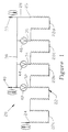
- FIG. 1 is a general schematic of an emitter made according to the present invention.
- FIG. 2 is a partially cut away view of a longitudinal section of an emitter made according to the schematic of FIG. 1.
- FIG. 3 is a partially cut away, mirror-image view of the reverse side of the emitter of FIG. 2.
- FIG. 4 is a cross section view of the emitter of FIG. 2 taken in the plane of that figure.
- FIG. 5 is a cross section view taken along line 5-5 of FIG. 2, which view is orthogonal to the view of FIG. 4.
- FIG. 6 is a cross section view taken along line 6-6 of FIG. 2.
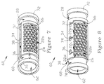
- FIG. 7 is a perspective view of an insert portion of the emitter of FIG. 2.
- FIG. 8 is a rear, mirror-image perspective view of the insert of FIG. 7.
- FIG. 9 is a partial fragmentary perspective view (not to scale) of the insert of FIG. 7 illustrating operation under low fluid-pressure conditions.
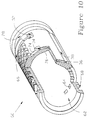
- FIG. 10 is view similar to FIG. 9 illustrating operation under higher fluid-pressure conditions.
- FIG. 11 is a view similar to FIG. 6 also illustrating operation under higher fluid-pressure conditions.
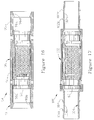
- FIG. 12 is a view similar to FIG. 4 showing an alternative embodiment operating under low fluid-pressure conditions.
- FIG. 13 is a view similar to FIG. 5 of the embodiment of FIG. 12.
- FIG. 14 is a view similar to FIG. 6 of the embodiment of FIG. 12.
- FIG. 15 is a view similar to FIG. 11 of the embodiment of FIG. 12 operating under higher fluid-pressure conditions.
- FIG. 16 is a view similar to FIG. 2 showing a third embodiment of the invention.
- FIG. 17 is a view similar to FIG. 3 showing a fourth embodiment of the invention.
- Emitter 20 has an extended fluid-turbulence passageway or labyrinth 22 having an inlet end 24, an outlet end 26, and respective sections 22a, 22b, 22c and 22d.
- the inlet end receives pressurized fluid from an irrigation pipe or conduit.
- the outlet end is coupled via an outlet line or chamber 28 to a low-pressure opening represented by arrow 30 to the exterior of the irrigation conduit in which, or attached to which, the emitter is operatively positioned.
- the labyrinth outlet end may also be directly connected to opening 30.
- Relatively free-flow fluid control channels 32, 34 and 36 are distributed along and in communication with labyrinth 22.
- Channel 32 is closest to the inlet end, and channel 36 is closest to the outlet end, as shown.
- Each control channel is also in communication with opening 30 via a bypass channel 38.
- Bypass channel 38 is also preferably coupled to a second conduit opening 40.
- valves 42, 44 and 46 Positioned at channels 32, 34 and 36 are valves 42, 44 and 46, respectively. Each of these is responsive to the fluid pressure at the inlet end of the labyrinth for selectively closing and opening the channels. At low fluid pressures, all of the valves are open. Fluid will primarily flow in the path of least resistance. This is the shortest labyrinth section 22a. As the pressure increases to a first predetermined value, valve 42 closes, preventing fluid flow in channel 32. This forces the fluid in the labyrinth to then flow through section 22b and out through channel 34.
- valve 44 closes, forcing the fluid to flow through an even longer labyrinth, represented by labyrinth sections 22a, 22b and 22c.
- valve 46 also closes, requiring the fluid to flow through the entire, and therefore maximum, length of labyrinth 22.
- Emitter 20 is preferably formed of an outer member, such as sleeve 50, which may be integral with an irrigation conduit 52. It may also be a member formed in or attached to a portion of a conduit and does not need to be a complete sleeve.
- Sleeve 50 has a plurality of openings, such as openings 30 and 40, discussed above, as well as openings 53 and 54 shown in FIGs. 2-4, and openings 55, 56, 57 and 58 shown in FIG. 5. These openings assure that the fluid pressure at the outputs of control channels 32, 34 and 36 are at atmospheric pressure. The function of the valves is then only dependent on the internal pressure of the fluid in the conduit.
- insert 60 Disposed within outer member 50 is an inner member formed as a generally tubular inner insert 60.
- insert 60 has an inner surface 61 that defines, at least in part, an inner chamber 62 that preferably provides an uninterrupted continuation of the fluid flow inside conduit 52.
- a series of inlet openings shown generally at 64 provide communication between chamber 62 and inlet end 24 of labyrinth 22.
- Labyrinth section 22a follows a serpentine path from inlet end 24 to an intermediate annular channel 66 that is in communication with control channel 32, as shown in FIG. 3.
- FIG. 3 is shown as a mirror image of the reverse side of insert 60 as shown in FIG. 2 in order to align the functional portions of the insert. That is, intermediate channel 66 is on the right in both figures as shown.
- the labyrinth extends from the inlet end on the left end of the insert in FIG. 2, to the right through section 22a until channel 66 is reached.
- the labyrinth then continues from the right at channel 66 in FIG. 3, through sections 22b, 22c and 22d, to outlet end 26 shown at the left.
- fluid flow through the labyrinth is readily visualized.
- a second annular outlet chamber 68 substantially the same as outlet chamber 28, extends circumferentially around the left end of the insert, as shown in FIGs. 2-5. Shoulders 70 and 72 at the respective left and right ends of insert 60 seal the outlet chambers from the internal conduit fluid flow.
- FIG. 6 shows insert 60 in cross section.
- Labyrinth section 22a is shown at the left and an end portion of section 22b is shown at the right of the figure.
- a channel arm 74 shown in dashed lines, connects labyrinth section 22b to channel 34, shown along the top.
- a wall 76 formed integrally in insert 60, is disposed between inner chamber 62 and channel 34.
- Insert 60 in this embodiment is made of a synthetic resilient material, so wall 76 is a resilient web that is deformable under the pressure of fluid in the inner chamber to extend into channel 34. The wall therefore functions as a valve, as represented by valve 44 shown in FIG. 1.
- Each of channels 32 and 36 also have walls similar to wall 76. By making these walls progressively thicker, from channel 32 to 36, or by making the width of the channels progressively narrower, the pressure required to deform the walls sufficiently to close the channels, as shown in FIG. 11, increases with each channel along the labyrinth. The operation of emitter 20 is therefore as was described with reference to the schematic of FIG. 1.
- FIGs. 9-11 are partial fragmentary perspective views (not to scale) of insert 60.
- Control channels 34 and 36 are shown in partial cross section. In FIG. 9, these channels are open, such as would be the case when the conduit fluid pressure is low.
- FIG. 10 illustrates the control channels in a closed condition or state, as they would be under higher conduit fluid pressure conditions.
- FIG. 11 also shows channel 34 in a closed condition. When the fluid pressure in the conduit is high enough to close all of the control channels, the fluid is forced to travel the length of the entire labyrinth.
- the controlled rate of flow through emitter 20 is directly related to:
- FIGs. 12-15 An emitter 78 mounted in a conduit 52 has fluid passageways the same as emitter 20, which passageways are given the same reference numbers to simplify discussions.
- the control channels 32, 34 and 36 are the same in shape.
- tapered apertures 82, 84 and 86, respectively, exist between the channels and inner chamber 62, as particularly shown in FIGs. 14 and 15.
- Each of the apertures has inserted in it a conformably shaped flexible membrane 88, 90 or 92.
- These membranes are structured to deform at predetermined pressures, as was the case for the walls associated with insert 60.
- insert 80 may be made of a rigid thermoplastic material.
- each of tapered apertures 88, 90 and 92 are corresponding access apertures 89, 91 and 93, respectively. These apertures are required during manufacture of insert 80 to provide access to the tapered apertures, and do not affect the functionality of the emitter.
- membranes 88, 90 and 92 and the shapes of apertures 82, 84 and 86 are used to determine the pressures at which the associated control channels will close. By proper coordination of these and other mentioned parameters, a substantially constant flow condition is feasible.
- the membranes be structured in a way that results in the rapid closing of the associated control channels.
- One way that this can be done is to form the membrane with a slight curvature (not shown) into the inner chamber. When the requisite pressure is reached, the membrane will snap into the channel, blocking the fluid flow therein. Other designs may also be used.
- FIGs. 16 and 17 show two other ways that inserts 60 or 80 could be mounted in an outer sleeve to form an emitter.
- FIG. 16 shows an emitter 94 in which the insert is mounted in an outer sleeve 96 having a first section 96a sized to receive snugly insert 60 and a second section 96b sized slightly less than the outer diameter of the insert, in order to form a shoulder 96c that limits the travel of the insert.
- a cap member 98 has a tubular extension 98a with an outer diameter conforming to that of section 96a, and an inner diameter conforming generally to that of section 96b. When fixedly mounted in section 96a, as shown, cap member 98 captures the insert in sleeve 96.
- sleeve 96 and cap member 98 have inwardly tapered openings with ridges 96d and 98b that grasp the mating ends of an irrigation pipe conduit in which the emitter is positioned.
- FIG. 17 shows an emitter 100, similar to emitter 94, in which insert 60 is mounted in an outer sleeve 102, and is held there by a cap member 104, as shown.
- the ends 102a and 104a of the sleeve and cap member, respectively, are formed with a reduced diameter and exterior ridges, such as ridges 102b and 102c, and 104b and 104c. These ends are matingly and sealingly received in associated ends of irrigation conduit.
- FIGs. 16 and 17 an embodiment similar to those of FIGs. 16 and 17 could be made in which one end of the insert is sealed to prevent fluid flowing through the inner chamber, with the opposite end of the fluid chamber connected to a separate uninterrupted irrigation conduit through a tube extending into the conduit.
- Such an emitter can be used as an attachment to the conduit, rather than being built into it, as is the case of emitter 20, or rather than being inserted between adjacent ends of conduit, as is the case with emitters 94 and 100.
- the invention could be formed of non-tubular members attached along a portion of a conduit wall.
Landscapes
- Life Sciences & Earth Sciences (AREA)
- Soil Sciences (AREA)
- Engineering & Computer Science (AREA)
- Water Supply & Treatment (AREA)
- Environmental Sciences (AREA)
- Infusion, Injection, And Reservoir Apparatuses (AREA)
- Nozzles (AREA)
- Check Valves (AREA)
- Safety Valves (AREA)
- Pipe Accessories (AREA)
- Measuring Fluid Pressure (AREA)
Applications Claiming Priority (2)
| Application Number | Priority Date | Filing Date | Title |
|---|---|---|---|
| US661880 | 1991-02-27 | ||
| US07/661,880 US5111996A (en) | 1991-02-27 | 1991-02-27 | Incremental pressure-compensating drip irrigation emitter |
Publications (2)
| Publication Number | Publication Date |
|---|---|
| EP0501114A1 true EP0501114A1 (fr) | 1992-09-02 |
| EP0501114B1 EP0501114B1 (fr) | 1996-03-27 |
Family
ID=24655490
Family Applications (1)
| Application Number | Title | Priority Date | Filing Date |
|---|---|---|---|
| EP92100446A Expired - Lifetime EP0501114B1 (fr) | 1991-02-27 | 1992-01-13 | Emetteur d'arrosage goutte à goutte avec dispositif de compensation de pression incrémentale |
Country Status (21)
| Country | Link |
|---|---|
| US (1) | US5111996A (fr) |
| EP (1) | EP0501114B1 (fr) |
| JP (1) | JPH04317758A (fr) |
| CN (1) | CN1046400C (fr) |
| AU (1) | AU647870B2 (fr) |
| BR (1) | BR9200598A (fr) |
| CA (1) | CA2061846C (fr) |
| DE (1) | DE69209343D1 (fr) |
| DZ (1) | DZ1561A1 (fr) |
| EC (1) | ECSP920816A (fr) |
| EG (1) | EG19710A (fr) |
| ES (1) | ES2084843T3 (fr) |
| GR (1) | GR3019467T3 (fr) |
| IL (1) | IL100912A (fr) |
| JO (1) | JO1700B1 (fr) |
| MA (1) | MA22451A1 (fr) |
| MX (1) | MX9200792A (fr) |
| NZ (1) | NZ241165A (fr) |
| TN (1) | TNSN92018A1 (fr) |
| TR (1) | TR26698A (fr) |
| ZA (1) | ZA92154B (fr) |
Cited By (5)
| Publication number | Priority date | Publication date | Assignee | Title |
|---|---|---|---|---|
| EP0620966A1 (fr) * | 1991-03-15 | 1994-10-26 | Lego M. Lemelshtrich Ltd. | Appareil d'irrigation goutte à goutte |
| GR1002496B (el) * | 1995-05-31 | 1996-12-13 | Giuffre Carmelo | Συσκευη αρδευσης με διδυμες οπες εκροης. |
| ES2137825A1 (es) * | 1996-02-16 | 1999-12-16 | Twin Drops Iberica S A | Gotero autocompensante y antidescarga para riegos uniformes. |
| WO2006038246A1 (fr) * | 2004-10-08 | 2006-04-13 | Agriplast S.R.L. | Tuyau d'irrigation goutte a goutte dote d'elements d'egouttement interne, et elements d'egouttement destines a ce tuyau |
| WO2016071722A2 (fr) | 2014-11-04 | 2016-05-12 | Emmanuil Dermitzakis | Émetteur cylindrique à filtre à eau et procédé |
Families Citing this family (69)
| Publication number | Priority date | Publication date | Assignee | Title |
|---|---|---|---|---|
| GR1000745B (el) * | 1991-08-01 | 1992-12-30 | Eurodrip A V E G E Anonymos Vi | Σταλλακτης μεσα σε αγωγο ποτισματος σε σταγονες, αντισταθμιζων με αυτορρυθμιση την πιεση του νερου. |
| US5332160A (en) * | 1992-10-26 | 1994-07-26 | Agrifim Irrigation International N.V. | Multi-layer drip irrigation conduit |
| WO1995013882A1 (fr) * | 1992-10-26 | 1995-05-26 | Agrifim Irrigation International N.V. | Conduite a couches multiples pour l'irrigation au goutte a goutte |
| IL106572A0 (en) * | 1992-11-19 | 1993-12-08 | Paskal Avizarey Kshira Ltd | Outlet connector for irrigation pipe |
| US6394412B2 (en) * | 1993-04-02 | 2002-05-28 | Netafim (A.C.S.) Ltd. | Controlled valve |
| US5400973A (en) * | 1993-07-30 | 1995-03-28 | Cohen; Amir | Pressure responsive regulated flow restrictor useful for drip irrigation |
| US5615838A (en) * | 1995-03-10 | 1997-04-01 | Drip Irrigation Systems, Ltd. | In-line retention drip emitter |
| IL118377A (en) * | 1996-05-22 | 2001-12-23 | Cohen Amir | Irrigation emitters having reduced sensitivity to clogging |
| WO2000030433A1 (fr) | 1998-11-20 | 2000-06-02 | T-Systems International, Inc. | Tuyau d'irrigation au goutte a goutte avec emetteurs a debits multiples |
| US6238081B1 (en) | 1999-03-23 | 2001-05-29 | Hydro Systems Company | Ultra-lean dilution apparatus |
| US20020104902A1 (en) | 2001-02-08 | 2002-08-08 | Eran Eckstein | Inline dripper with micro-tube connector |
| WO2002074444A2 (fr) | 2001-03-16 | 2002-09-26 | The Toro Company | Emetteur |
| US6817548B2 (en) * | 2001-09-05 | 2004-11-16 | R.M. Wade & Co. | Fluid distribution emitter and system |
| US6821928B2 (en) * | 2001-11-06 | 2004-11-23 | Rodney Ruskin | Method to reduce the rate of diffusion of slow-release materials through polymers and process for making drip irrigation devices with long-term control of root growth |
| US6695231B2 (en) | 2002-02-15 | 2004-02-24 | Dramm Corporation | Irrigation system for growing plants at a growing facility |
| WO2003106041A1 (fr) * | 2002-06-13 | 2003-12-24 | Sergey Stanislavovich Morozov | Dispositif de regulation d'un flux de milieu s'ecoulant d'un recipient de stockage de milieu |
| US6752795B2 (en) * | 2002-06-24 | 2004-06-22 | Bausch & Lomb Incorporated | Adjustable fluid flow resistor cassette |
| US20050284966A1 (en) * | 2004-06-23 | 2005-12-29 | Defrank Michael | Emitter |
| US7108205B1 (en) * | 2005-03-01 | 2006-09-19 | D.R.T.S. Enterprises Ltd. | Drip irrigation system employing parallel adjacent flowpaths |
| WO2006105364A2 (fr) * | 2005-03-31 | 2006-10-05 | Rain Bird Corporation | Emetteur d'egouttement |
| US7360814B2 (en) * | 2005-12-02 | 2008-04-22 | Castagno Leo L | Interior space expansion system |
| US20070189852A1 (en) * | 2006-01-31 | 2007-08-16 | Greg Wolfley | Modular network irrigation system |
| US7648085B2 (en) | 2006-02-22 | 2010-01-19 | Rain Bird Corporation | Drip emitter |
| US20100024280A1 (en) * | 2008-08-04 | 2010-02-04 | Subterranean Termite Solutions, LLC | Termite Control System and Method |
| US8628032B2 (en) * | 2008-12-31 | 2014-01-14 | Rain Bird Corporation | Low flow irrigation emitter |
| US8439282B2 (en) * | 2009-02-06 | 2013-05-14 | Rain Bird Corporation | Low flow irrigation emitter |
| US20100282873A1 (en) * | 2009-05-06 | 2010-11-11 | Mattlin Jeffrey L | Drip Emitter and Methods of Assembly and Mounting |
| BR112012020305B1 (pt) | 2010-02-18 | 2018-05-08 | Netafim Ltd | emissor de irrigação por gotas |
| JP5960148B2 (ja) | 2010-11-08 | 2016-08-02 | アクティヴパック, インコーポレイテッド | 有益薬品分配器 |
| US8511586B2 (en) | 2011-04-20 | 2013-08-20 | Deere & Company | Disc shaped regulated drip irrigation emitter |
| GB2496832B (en) | 2011-05-16 | 2013-11-13 | Uri Alkalay | Cylindrical drip irrigation emitter |
| CN102698897A (zh) * | 2011-11-29 | 2012-10-03 | 新疆惠利灌溉科技有限公司 | 内嵌式滴灌管滴头 |
| US9877440B2 (en) | 2012-03-26 | 2018-01-30 | Rain Bird Corporation | Elastomeric emitter and methods relating to same |
| US20130248622A1 (en) | 2012-03-26 | 2013-09-26 | Jae Yung Kim | Drip line and emitter and methods relating to same |
| US10440903B2 (en) | 2012-03-26 | 2019-10-15 | Rain Bird Corporation | Drip line emitter and methods relating to same |
| US9485923B2 (en) | 2012-03-26 | 2016-11-08 | Rain Bird Corporation | Elastomeric emitter and methods relating to same |
| CN102806155B (zh) * | 2012-08-21 | 2015-02-04 | 兰州兰泰天翼节水器材有限公司 | 圆柱体锯齿形迷宫式双流道灌水器 |
| CN103026949B (zh) * | 2013-01-17 | 2014-03-26 | 中国农业大学 | 一种调压性能稳定的毛管压力调节器 |
| CN103026948B (zh) * | 2013-01-17 | 2014-03-26 | 中国农业大学 | 一种毛管压力调节器 |
| US9173353B2 (en) | 2013-03-11 | 2015-11-03 | International Business Machines Corporation | Irrigation system |
| US9149011B2 (en) | 2013-03-11 | 2015-10-06 | International Business Machines Corporation | Controllable emitter |
| US9167757B2 (en) | 2013-03-11 | 2015-10-27 | International Business Machines Corporation | Irrigation system and method |
| US9872444B2 (en) | 2013-03-15 | 2018-01-23 | Rain Bird Corporation | Drip emitter |
| US9258949B2 (en) | 2013-06-19 | 2016-02-16 | National Diversified Sales, Inc. | Adjustable drip emitter |
| CN103301963B (zh) * | 2013-07-10 | 2016-08-10 | 安徽省(水利部淮河水利委员会)水利科学研究院 | 迷宫式超低压滴灌滴头 |
| US10285342B2 (en) | 2013-08-12 | 2019-05-14 | Rain Bird Corporation | Elastomeric emitter and methods relating to same |
| US10631473B2 (en) | 2013-08-12 | 2020-04-28 | Rain Bird Corporation | Elastomeric emitter and methods relating to same |
| USD811179S1 (en) | 2013-08-12 | 2018-02-27 | Rain Bird Corporation | Emitter part |
| US9883640B2 (en) | 2013-10-22 | 2018-02-06 | Rain Bird Corporation | Methods and apparatus for transporting elastomeric emitters and/or manufacturing drip lines |
| CN103861752B (zh) * | 2014-03-03 | 2016-01-13 | 西安交通大学 | 基于文丘里原理的抗堵灌水器 |
| US10330559B2 (en) | 2014-09-11 | 2019-06-25 | Rain Bird Corporation | Methods and apparatus for checking emitter bonds in an irrigation drip line |
| CN104303957B (zh) * | 2014-10-21 | 2017-01-11 | 河北雨燕灌溉设备有限公司 | 一种微孔迷宫防堵滴灌管 |
| CN104455527A (zh) * | 2014-11-21 | 2015-03-25 | 苏州福润机械有限公司 | 一种内置弯道防回流球阀 |
| JP6532763B2 (ja) * | 2015-02-25 | 2019-06-19 | 株式会社エンプラス | エミッタおよび点滴灌漑用チューブ |
| CN105104109B (zh) * | 2015-09-06 | 2017-04-12 | 新疆农垦科学院 | 一种密植作物灌水器 |
| CN105123433B (zh) * | 2015-09-06 | 2017-04-12 | 新疆农垦科学院 | 一种稀植作物灌水器 |
| CN106895614B (zh) * | 2015-12-18 | 2022-07-08 | 珠海凌达压缩机有限公司 | 压缩机及其分液器 |
| JP6689634B2 (ja) * | 2016-03-17 | 2020-04-28 | 株式会社エンプラス | エミッタおよび点滴灌漑用チューブ |
| CN106171848B (zh) * | 2016-06-22 | 2022-05-24 | 青岛新大成塑料机械有限公司 | 内镶片式压力补偿滴头、滴灌带及滴灌方法 |
| US10375904B2 (en) | 2016-07-18 | 2019-08-13 | Rain Bird Corporation | Emitter locating system and related methods |
| US11051466B2 (en) | 2017-01-27 | 2021-07-06 | Rain Bird Corporation | Pressure compensation members, emitters, drip line and methods relating to same |
| US10440904B2 (en) * | 2017-04-19 | 2019-10-15 | Sgt Co., Ltd. | Drip emitter |
| US10626998B2 (en) | 2017-05-15 | 2020-04-21 | Rain Bird Corporation | Drip emitter with check valve |
| CN107143674B (zh) * | 2017-07-11 | 2023-03-17 | 新疆水利水电科学研究院 | 压力平衡装置和压力平衡系统 |
| USD883048S1 (en) | 2017-12-12 | 2020-05-05 | Rain Bird Corporation | Emitter part |
| US11985924B2 (en) | 2018-06-11 | 2024-05-21 | Rain Bird Corporation | Emitter outlet, emitter, drip line and methods relating to same |
| CN109699457A (zh) * | 2019-02-26 | 2019-05-03 | 甘肃省林业科学研究院 | 可拆卸压力补偿式滴头 |
| CN111264349A (zh) * | 2020-04-01 | 2020-06-12 | 秦春明 | 农业用防堵滴灌供水管及其加工方法 |
| CN111527856B (zh) * | 2020-05-28 | 2021-06-25 | 安徽省益丰生态农业科技有限公司 | 用于水肥一体化的滴灌装置 |
Citations (2)
| Publication number | Priority date | Publication date | Assignee | Title |
|---|---|---|---|---|
| US4008853A (en) * | 1975-10-31 | 1977-02-22 | Vernay Laboratories, Inc. | Pressure responsive self-purging emitter |
| US4824025A (en) * | 1987-05-26 | 1989-04-25 | Miller David B | One-piece in-line pressure compensating drip irrigation emitter |
Family Cites Families (15)
| Publication number | Priority date | Publication date | Assignee | Title |
|---|---|---|---|---|
| US3815636A (en) * | 1971-06-23 | 1974-06-11 | Iplex Plastic Ind Pty Ltd | Pressure reducing valve and flow control device |
| US3998244A (en) * | 1975-08-08 | 1976-12-21 | Clarence Bentley | Drip irrigation valve with helical flow path |
| IL67824A (en) * | 1977-11-24 | 1985-08-30 | Hydro Plan Eng Ltd | Irrigation drip emitter unit |
| US4354639A (en) * | 1977-12-16 | 1982-10-19 | Delmer William M | Multiple chamber drip irrigation hose |
| US4382549A (en) * | 1979-02-05 | 1983-05-10 | Christy Mark H | Irrigation emitter |
| US4344576A (en) * | 1980-09-15 | 1982-08-17 | Smith Allan L | Trickle flow irrigation valve |
| US4506423A (en) * | 1980-12-24 | 1985-03-26 | Hitachi, Ltd. | Method of producing a fluid pressure reducing device |
| US4473191A (en) * | 1982-04-01 | 1984-09-25 | Chapin Richard D | Drip irrigation system employing flow regulation |
| US4600152A (en) * | 1983-06-06 | 1986-07-15 | Samuel Samueli | Multiple intersection dripper |
| US4613080A (en) * | 1984-06-29 | 1986-09-23 | Rain Bird Sprinkler Mfg. Corp. | Multiple outlet trickle irrigation unit |
| GB8431405D0 (en) * | 1984-12-12 | 1985-01-23 | Sanville F E | Fluid power valves |
| US4653695A (en) * | 1985-09-11 | 1987-03-31 | Drip Irrigation Systems, Ltd. | Pressure compensating drip irrigation emitter |
| IL76553A (en) * | 1985-10-03 | 1993-01-31 | Naan Mech Works | Drip irrigation apparatus |
| FR2625544A1 (fr) * | 1987-12-31 | 1989-07-07 | Rolland Gilbert | Conduit de forme particuliere destine a la micro-irrigation des sols par des appareils distributeurs ou goutteurs |
| US4917535A (en) * | 1989-04-19 | 1990-04-17 | Aquapore Moisture Systems | Pressure compensating flow rate control device with dual operating modes |
-
1991
- 1991-02-27 US US07/661,880 patent/US5111996A/en not_active Expired - Lifetime
- 1991-12-23 NZ NZ241165A patent/NZ241165A/xx unknown
-
1992
- 1992-01-09 ZA ZA92154A patent/ZA92154B/xx unknown
- 1992-01-09 AU AU10123/92A patent/AU647870B2/en not_active Ceased
- 1992-01-13 EP EP92100446A patent/EP0501114B1/fr not_active Expired - Lifetime
- 1992-01-13 ES ES92100446T patent/ES2084843T3/es not_active Expired - Lifetime
- 1992-01-13 DE DE69209343T patent/DE69209343D1/de not_active Expired - Lifetime
- 1992-01-25 EG EG4492A patent/EG19710A/xx active
- 1992-02-10 IL IL10091292A patent/IL100912A/en not_active IP Right Cessation
- 1992-02-12 JP JP4025061A patent/JPH04317758A/ja active Pending
- 1992-02-19 TR TR92/0172A patent/TR26698A/xx unknown
- 1992-02-24 JO JO19921700A patent/JO1700B1/en active
- 1992-02-24 BR BR929200598A patent/BR9200598A/pt not_active IP Right Cessation
- 1992-02-25 MX MX9200792A patent/MX9200792A/es unknown
- 1992-02-25 CA CA002061846A patent/CA2061846C/fr not_active Expired - Fee Related
- 1992-02-26 MA MA22739A patent/MA22451A1/fr unknown
- 1992-02-26 DZ DZ920019A patent/DZ1561A1/fr active
- 1992-02-27 TN TNTNSN92018A patent/TNSN92018A1/fr unknown
- 1992-02-27 EC EC1992000816A patent/ECSP920816A/es unknown
- 1992-02-27 CN CN92101386A patent/CN1046400C/zh not_active Expired - Fee Related
-
1996
- 1996-03-29 GR GR960400846T patent/GR3019467T3/el unknown
Patent Citations (2)
| Publication number | Priority date | Publication date | Assignee | Title |
|---|---|---|---|---|
| US4008853A (en) * | 1975-10-31 | 1977-02-22 | Vernay Laboratories, Inc. | Pressure responsive self-purging emitter |
| US4824025A (en) * | 1987-05-26 | 1989-04-25 | Miller David B | One-piece in-line pressure compensating drip irrigation emitter |
Cited By (5)
| Publication number | Priority date | Publication date | Assignee | Title |
|---|---|---|---|---|
| EP0620966A1 (fr) * | 1991-03-15 | 1994-10-26 | Lego M. Lemelshtrich Ltd. | Appareil d'irrigation goutte à goutte |
| GR1002496B (el) * | 1995-05-31 | 1996-12-13 | Giuffre Carmelo | Συσκευη αρδευσης με διδυμες οπες εκροης. |
| ES2137825A1 (es) * | 1996-02-16 | 1999-12-16 | Twin Drops Iberica S A | Gotero autocompensante y antidescarga para riegos uniformes. |
| WO2006038246A1 (fr) * | 2004-10-08 | 2006-04-13 | Agriplast S.R.L. | Tuyau d'irrigation goutte a goutte dote d'elements d'egouttement interne, et elements d'egouttement destines a ce tuyau |
| WO2016071722A2 (fr) | 2014-11-04 | 2016-05-12 | Emmanuil Dermitzakis | Émetteur cylindrique à filtre à eau et procédé |
Also Published As
| Publication number | Publication date |
|---|---|
| JPH04317758A (ja) | 1992-11-09 |
| ZA92154B (en) | 1992-10-28 |
| CN1046400C (zh) | 1999-11-17 |
| CA2061846C (fr) | 2001-06-19 |
| BR9200598A (pt) | 1992-10-27 |
| TR26698A (tr) | 1995-05-15 |
| DE69209343D1 (de) | 1996-05-02 |
| EG19710A (en) | 1995-12-31 |
| CA2061846A1 (fr) | 1992-08-28 |
| IL100912A (en) | 1994-05-30 |
| JO1700B1 (en) | 1992-12-15 |
| AU647870B2 (en) | 1994-03-31 |
| US5111996A (en) | 1992-05-12 |
| ES2084843T3 (es) | 1996-05-16 |
| IL100912A0 (en) | 1992-11-15 |
| EP0501114B1 (fr) | 1996-03-27 |
| TNSN92018A1 (fr) | 1993-06-08 |
| GR3019467T3 (en) | 1996-06-30 |
| MX9200792A (es) | 1992-08-01 |
| MA22451A1 (fr) | 1992-10-01 |
| CN1064189A (zh) | 1992-09-09 |
| ECSP920816A (es) | 1992-12-21 |
| NZ241165A (en) | 1993-05-26 |
| AU1012392A (en) | 1992-09-03 |
| DZ1561A1 (fr) | 2002-02-17 |
Similar Documents
| Publication | Publication Date | Title |
|---|---|---|
| US5111996A (en) | Incremental pressure-compensating drip irrigation emitter | |
| EP0295400B1 (fr) | Dispositif d'irrigation goutte à goutte en une seule pièce avec compensation de pression et étant inséré dans un tuyau | |
| US6302338B1 (en) | Drip irrigation lines | |
| EP0709020B1 (fr) | Bande d'irrigation à débit constant et procédé de production d'une telle bande | |
| US5829686A (en) | Irrigation emitters having reduced sensitivity to clogging | |
| EP0730822B1 (fr) | Dispositif de retenue avec une conduite inserrée dans un tube pour la distribution pour l'irrigation goutte à goutte | |
| EP1435196B1 (fr) | Distributeur d'arrosage goutte-à-goutte amélioré | |
| EP0241836A1 (fr) | Appareil d'irrigation goutte à goutte | |
| US4984739A (en) | Drip irrigation hose | |
| US3998244A (en) | Drip irrigation valve with helical flow path | |
| AU779778B2 (en) | Pressure compensating drip tape | |
| US6764029B2 (en) | Water irrigation system and method, and control unit useful therein | |
| BG96932A (bg) | Емитиращи поток приспособления и матрици , използвани за тяхното производство | |
| US3797754A (en) | Continuous tube trickle irrigation | |
| HUT68353A (en) | Regulated drip irrigation emitter | |
| GB1589529A (en) | Irrigation system | |
| US3908694A (en) | Emitter valve for subterranean irrigation systems | |
| US6260769B1 (en) | Irrigation assembly | |
| US4715543A (en) | Flow restrictor device particularly useful for drip irrigation | |
| US10869434B2 (en) | Elliptical in line button dripper with extended bonding zones | |
| GB1582890A (en) | Valve for an irrigation system | |
| IL97577A (en) | Flexible pipe for drip irrigation provided with integrated emitters | |
| KR0125797B1 (ko) | 큰 직경 파이프의 관개노즐 | |
| JPS6255034B2 (fr) | ||
| JPS62524B2 (fr) |
Legal Events
| Date | Code | Title | Description |
|---|---|---|---|
| PUAI | Public reference made under article 153(3) epc to a published international application that has entered the european phase |
Free format text: ORIGINAL CODE: 0009012 |
|
| AK | Designated contracting states |
Kind code of ref document: A1 Designated state(s): CH DE ES FR GB GR IT LI |
|
| 17P | Request for examination filed |
Effective date: 19930212 |
|
| 17Q | First examination report despatched |
Effective date: 19940303 |
|
| GRAA | (expected) grant |
Free format text: ORIGINAL CODE: 0009210 |
|
| AK | Designated contracting states |
Kind code of ref document: B1 Designated state(s): CH DE ES FR GB GR IT LI |
|
| PG25 | Lapsed in a contracting state [announced via postgrant information from national office to epo] |
Ref country code: LI Effective date: 19960327 Ref country code: CH Effective date: 19960327 |
|
| ITF | It: translation for a ep patent filed |
Owner name: ING. A. GIAMBROCONO & C. S.R.L. |
|
| REF | Corresponds to: |
Ref document number: 69209343 Country of ref document: DE Date of ref document: 19960502 |
|
| REG | Reference to a national code |
Ref country code: ES Ref legal event code: FG2A Ref document number: 2084843 Country of ref document: ES Kind code of ref document: T3 |
|
| REG | Reference to a national code |
Ref country code: GR Ref legal event code: FG4A Free format text: 3019467 |
|
| ET | Fr: translation filed | ||
| PG25 | Lapsed in a contracting state [announced via postgrant information from national office to epo] |
Ref country code: DE Effective date: 19960628 |
|
| REG | Reference to a national code |
Ref country code: CH Ref legal event code: PL |
|
| PLBE | No opposition filed within time limit |
Free format text: ORIGINAL CODE: 0009261 |
|
| STAA | Information on the status of an ep patent application or granted ep patent |
Free format text: STATUS: NO OPPOSITION FILED WITHIN TIME LIMIT |
|
| 26N | No opposition filed | ||
| PGFP | Annual fee paid to national office [announced via postgrant information from national office to epo] |
Ref country code: FR Payment date: 20001228 Year of fee payment: 10 |
|
| PGFP | Annual fee paid to national office [announced via postgrant information from national office to epo] |
Ref country code: GR Payment date: 20010102 Year of fee payment: 10 |
|
| PGFP | Annual fee paid to national office [announced via postgrant information from national office to epo] |
Ref country code: GB Payment date: 20010110 Year of fee payment: 10 |
|
| REG | Reference to a national code |
Ref country code: GB Ref legal event code: IF02 |
|
| PG25 | Lapsed in a contracting state [announced via postgrant information from national office to epo] |
Ref country code: GB Free format text: LAPSE BECAUSE OF NON-PAYMENT OF DUE FEES Effective date: 20020113 |
|
| PG25 | Lapsed in a contracting state [announced via postgrant information from national office to epo] |
Ref country code: GR Free format text: LAPSE BECAUSE OF NON-PAYMENT OF DUE FEES Effective date: 20020812 |
|
| GBPC | Gb: european patent ceased through non-payment of renewal fee |
Effective date: 20020113 |
|
| PG25 | Lapsed in a contracting state [announced via postgrant information from national office to epo] |
Ref country code: FR Free format text: LAPSE BECAUSE OF NON-PAYMENT OF DUE FEES Effective date: 20020930 |
|
| REG | Reference to a national code |
Ref country code: FR Ref legal event code: ST |
|
| PG25 | Lapsed in a contracting state [announced via postgrant information from national office to epo] |
Ref country code: IT Free format text: LAPSE BECAUSE OF NON-PAYMENT OF DUE FEES;WARNING: LAPSES OF ITALIAN PATENTS WITH EFFECTIVE DATE BEFORE 2007 MAY HAVE OCCURRED AT ANY TIME BEFORE 2007. THE CORRECT EFFECTIVE DATE MAY BE DIFFERENT FROM THE ONE RECORDED. Effective date: 20050113 |
|
| PGFP | Annual fee paid to national office [announced via postgrant information from national office to epo] |
Ref country code: ES Payment date: 20060130 Year of fee payment: 15 |
|
| REG | Reference to a national code |
Ref country code: ES Ref legal event code: FD2A Effective date: 20070115 |
|
| PG25 | Lapsed in a contracting state [announced via postgrant information from national office to epo] |
Ref country code: ES Free format text: LAPSE BECAUSE OF NON-PAYMENT OF DUE FEES Effective date: 20070115 |