EP0501002B1 - Optic rotation sensing apparatus and related method - Google Patents
Optic rotation sensing apparatus and related method Download PDFInfo
- Publication number
- EP0501002B1 EP0501002B1 EP91113045A EP91113045A EP0501002B1 EP 0501002 B1 EP0501002 B1 EP 0501002B1 EP 91113045 A EP91113045 A EP 91113045A EP 91113045 A EP91113045 A EP 91113045A EP 0501002 B1 EP0501002 B1 EP 0501002B1
- Authority
- EP
- European Patent Office
- Prior art keywords
- phase
- signal
- light
- detecting
- reference signal
- Prior art date
- Legal status (The legal status is an assumption and is not a legal conclusion. Google has not performed a legal analysis and makes no representation as to the accuracy of the status listed.)
- Expired - Lifetime
Links
Images


Classifications
-
- G—PHYSICS
- G01—MEASURING; TESTING
- G01C—MEASURING DISTANCES, LEVELS OR BEARINGS; SURVEYING; NAVIGATION; GYROSCOPIC INSTRUMENTS; PHOTOGRAMMETRY OR VIDEOGRAMMETRY
- G01C19/00—Gyroscopes; Turn-sensitive devices using vibrating masses; Turn-sensitive devices without moving masses; Measuring angular rate using gyroscopic effects
- G01C19/58—Turn-sensitive devices without moving masses
- G01C19/64—Gyrometers using the Sagnac effect, i.e. rotation-induced shifts between counter-rotating electromagnetic beams
- G01C19/72—Gyrometers using the Sagnac effect, i.e. rotation-induced shifts between counter-rotating electromagnetic beams with counter-rotating light beams in a passive ring, e.g. fibre laser gyrometers
- G01C19/721—Details, e.g. optical or electronical details
Definitions
- This invention relates to an optic rotation sensing apparatus such as a fiber-optic gyroscope. This invention also relates to a method related to an optic rotation detecting apparatus.
- US-A-4,013,365 discloses a basic fiber-optic gyroscope.
- US-A-4,998,822 discloses an advanced fiber-optic gyroscope.
- Signal processing used in fiber-optic gyroscopes is of the phase-difference bias type, the two-input type, the phase-modulation type, the frequency-modulation type, and others.
- a prior art fiber-optic gyroscope includes a light source 1 such as a semiconductor laser. Light emitted from the light source 1 is transmitted via a first fiber-optic coupler 2 to a polarizer 4. After the light passes through the polarizer 4, the light is transmitted via a fiber-optic mode filter to a second fiber-optic coupler 5 forming a beam splitter.
- a light source 1 such as a semiconductor laser.
- the light is separated by the beam splitter 5 into two beams which couple with two ends of an optical fiber 6 respectively.
- the optical fiber 6 forms a sensing loop.
- a part of the optical fiber 6 which extends between one end and the sensing loop is associated with to a phase modulator 7 including a piezoelectric element.
- One of the two light beams propagates through the sensing loop 6 in the clockwise (CW) direction, and the other light beam propagates through the sensing loop 6 in the counterclockwise (CCW) direction.
- the two light beams are combined by the beam splitter 5 into a single return light beam.
- the return light beam is transmitted via the polarizer 4 and the first fiber-optic coupler 2 to a photodetector 3 such as a photodiode, being converted by the photodetector 3 into a corresponding electric signal.
- a reference signal generator 23 outputs a reference signal of a predetermined frequency fm to a drive circuit 33.
- the drive circuit 33 generates a phase modulating signal in correspondence with the reference signal, and feeds the phase modulating signal to the phase modulator 7.
- the phases of the light beams propagating through the optical fiber are modulated by the phase modulator 7 in accordance with the phase modulating signal.
- the output signal from the photodetector 3 is fed via a preamplifier 21 to a lock-in amplifier 24.
- the lock-in amplifier 24 receives the reference signal from the reference signal generator 23.
- the lock-in amplifier 24 subjects the photodetector output signal to a synchronous detection process by using the reference signal.
- the output signal from the lock-in amplifier 24 is converted by a signal processor 26 into a signal directly representing the angular velocity of the fiber-optic gyroscope.
- the signal processor 26 generates a feedback signal on the basis of the output signal from the lock-in amplifier 24.
- the feedback signal is fed to a drive circuit 25.
- the drive circuit 25 drives the light source 1 in response to the feedback signal.
- the light wave traveling in the direction of a rotation of the sensing loop has a longer transit time through the sensing loop than the light wave traveling opposite to the direction of the rotation.
- This difference in transit time is seen as a shift in the relative phases of the two light waves.
- a rotation of the fiber-optic gyroscope causes a difference in phase between the two light waves, that is, the CW light and the CCW light.
- the CW light and the CCW light are combined while interfering with each other.
- the resulting interference light causes a corresponding component of the output signal from the photodetector 3.
- the phase difference between the CW light and the CCW light is detected by analyzing the component of the output signal from the photodetector 3 which corresponds to the interference light.
- fm c/(2nL) where "c” denotes the speed of light in a vacuum, and "n” denotes the effective refractive index of the optical fiber 6 and "L” denotes the length of the sensing loop.
- a dual phase modulator is employed therein, consisting of two identical phase modulators placed at the opposite ends of the sensing loop and excited 180° out-of-phase. Thereby, environmental effects that undesirably excite both modulators are cancelled, since they excite both modulators in phase with nearly equal amplitudes and consequently do not produce any net modulation.
- the dual phase modulation requires identical phase modulators having identical lengths of coiled optical fibers, identical winding tensions and an identical bonding structure.
- the US-A-4 712 306 suggests to use a single-phase modulator which is connected to a driver by a switch such that the driving signal may alternately be supplied directly or via a 180° phase delay circuit in order to suppress environmental effects.
- the single-phase modulator suffers from the drawback that the sensing loop is unsymmetrically heated which results in a bias drift. Therefore, the use of a matched peir of symmetrically placed phase modulators is suggested.
- document GB-A-2 089 976 discloses a ring interferometer which, however, does not comprise any phase modulator at all, and wherein no considerations with regard to a reduction of bias noise components due to environmental effects are made.
- an effective noise reduction can be achieved simply by controlling the output signal of the photodetector at a certain noise minimizing phase, which is determined by the zero point phase values of the noise-phase responsive characteristic of the output signal of the fiber-optic gyroscope.
- Fig. 1 is a diagram of a prior art fiber-optic gyroscope.
- Fig. 2 is a diagram of a fiber-optic gyroscope.
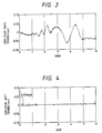
- Fig. 3 is a time-domain diagram showing drift characteristics of a zero-point output which is obtained in the absence of a depolarizer.
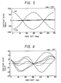
- Fig. 4 is a time-domain diagram showing drift characteristics of a zero-point output which is obtained in the presence of a depolarizer.
- Figs. 5-11 are diagrams showing the relation between a phase shift amount and a zero-point output level.
- Fig. 12 is a diagram of a fiber-optic gyroscope according to a first embodiment of this invention.
- Fig. 13 is a diagram showing time-domain variations of a zero-point output level in the fiber-optic gyroscope of Fig. 12.
- Fig. 14 is a diagram of a fiber-optic gyroscope according to a second embodiment of this invention.
- Fig. 15 is a diagram of a fiber-optic gyroscope according to a third embodiment of this invention.
- Fig. 16 is a diagram of a fiber-optic gyroscope according to a fourth embodiment of this invention.
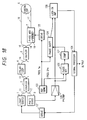
- Fig. 17 is a diagram of a fiber-optic gyroscope according to a fifth embodiment of this invention.
- Fig. 18 is a diagram of a fiber-optic gyroscope according to a sixth embodiment of this invention.
- Fig. 19 is a diagram of a fiber-optic gyroscope according to an seventh embodiment of this invention.
- Fig. 20 is a diagram of a fiber-optic gyroscope according to a eighth embodiment of this invention.
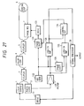
- Fig. 21 is a diagram of a fiber-optic gyroscope according to a ninth embodiment of this invention.
- Fig. 22 is a diagram of a fiber-optic gyroscope according to an tenth embodiment of this invention.
- Fig. 23 is a sectional view of a part of the sensing loop arrangement of Fig. 22.
- Fig. 24 is a block diagram of the control circuit of Fig. 17.
- a fiber-optic gyroscope includes a light source 1 using a super luminescence diode (an SLD).
- Light emitted from the light source 1 is guided to a first optical coupler 2 along an optical path 11 defined by an optical fiber.
- the first coupler 2 serves as a beam splitter.
- the light is separated by the first coupler 2 into two light beams having equal intensities.
- One of the light beams travels from the first coupler 2 to a laminated-type polarizer 4 via an optical path 13 defined by an optical fiber.
- the polarizer 4 confines the direction of the polarization of the light, and outputs light polarized in one direction.
- After passing through the polarizer 4, the light travels to a second optical coupler 5 via an optical path 14 defined by an optical fiber.
- the second coupler 5 serves as a beam splitter.
- the light is separated by the beam splitter 5 into two beams, which travel to a depolarizer 8 and a phase modulator 7 via optical paths 15 and 19 defined by optical fibers respectively.
- the depolarizer 8 serves to convert the polarized light into natural light.
- the light beam After passing through the depolarizer 8, the light beam enters a sensing loop 6 via an optical path 16 and then propagates through the sensing loop 6 in the clockwise (CW) direction.
- the light traveling through the sensing loop 6 in the CW direction will be referred to as the CW light hereinafter.
- the optical path 16 and the sensing loop 6 are defined by optical fibers.
- the CW light exits from the sensing loop 6, and then travels to the phase modulator 7 via an optical path 17 defined by an optical fiber.
- the CW light propagates through an optical path 18 defined by an optical fiber wound on a piezoelectric element of the phase modulator 7. After exiting from the phase modulator 7, the CW light travels to the second coupler 5 via the optical path 19. The other light beam passes through the optical path 18 within the phase modulator 7, and then travels to the sensing loop 6 via the optical path 17. The light beam enters the sensing loop 6 and propagates through the sensing loop 6 in the counterclockwise (CCW) direction. The light traveling through the sensing loop 6 in the CCW direction will be referred to as the CCW light.
- the CCW light exits from the sensing loop 6, and then travels to the depolarizer 8 via the optical path 16.
- the depolarizer 8 converts the light into natural light. After passing through the depolarizer 8, the CCW light travels to the second coupler 5 via the optical path 15.
- the CW light and the CCW light are combined by the second coupler 5 into a single return light beam while interfering with each other.
- the return light propagates to the first coupler 2 via the optical path 14, the polarizer 4, and the optical path 13.
- the return light is separated by the first coupler 2 into two light beams, one of which travels from the first coupler 2 to a photodiode 3 via an optical path 12 defined by an optical fiber.
- the light beam is converted by the photodiode 3 into a corresponding electric signal.
- the polarizer 4 is provided for the reason as follows.
- two modes of light waves which have orthogonal polarization directions can propagate in an optical fiber.
- the nonaxisymmetric characteristics of the optical fiber causes an energy coupling between the two orthogonal modes. If the energy coupling conditions change due to a temperature variation or other factors, an error is induced in the output signal from the fiber-optic gyroscope. Specifically, the error causes an drift in the output signal from the fiber-optic gyroscope.
- a good way of reducing such a drift in the output signal from the fiber-optic gyroscope is to equalize the transfer functions for the CW light and the CCW light.
- the polarizer 4 introduces a single polarization component of the forward light into the sensing loop 6, and the introduced light component is separated into the CW light and the CCW light. After traveling through the sensing loop 6, the CW light and the CCW light are combined into the return light. The polarizer 4 passes only a single polarization component of the return light which corresponds to the selected polarization component of the forward light.
- the depolarizer 8 is of the Lyot fiber type, including two polarization-plane conservative optical fibers having different lengths.
- the length of the longer optical fiber is twice the length of the shorter optical fiber.
- the two optical fibers are connected in such a manner that the main axes of the optical fibers incline to each other at an angle of 45 degrees.
- the depolarizer 8 produces a difference in optical path length between the orthogonal polarization modes, decreasing an interference between the orthogonal polarization modes.
- the depolarizer 8 depolarizes the CW light beam and the CCW light beam into natural light beams, removing unnecessary interference noise component caused by a variation in the polarization conditions in the sensing loop 6. As a result, it is possible to further reduce the drift in the output signal from the fiber-optic gyroscope.
- the phase modulator 7 provides an optical phase difference between the CW light and the CCW light.
- the phase modulator 7 includes a cylindrical piezoelectric element, and the optical fiber wound around the piezoelectric element and defining the optical path 18. While passing through the optical path 18 in the phase modulator 7, the CW light and the CCW light are subjected to phase modulation.
- This phase modulation is to increase the sensitivity in the detection of a Sagnac phase difference between the CW light and the CCW light which is caused by a rotation of the fiber-optic gyroscope.
- the optical fibers defining the optical paths 11, 12, 13, 14, 15, 16, 17, and 19 are of the single-mode type.
- the optical fiber defining the optical path 18 is preferably of the polarization-plane conservative type for the following reason.
- the piezoelectric element in the phase modulator 7 expands and contracts.
- the expansion and contraction of the piezoelectric element causes a stress in the optical fiber defining the optical path 18.
- the stress in the optical fiber unsettles the polarization conditions and the intensity of the light beams.
- the optical fiber defining the optical path 18 may be of the single-mode type.
- Fig. 3 shows the experimental results of the time-domain variations in the zero point of the output signal from the fiber-optic gyroscope which were obtained in the absence of the depolarizer 8.
- the drift quantity of the zero point of the output signal from the fiber-optic gyroscope was equal to about 0.1 degree/second in the absence of the depolarizer 8.
- FIG. 4 shows the experimental results of the time-domain variations in the zero point of the output signal from the fiber-optic gyroscope which were obtained in the presence of the depolarizer 8. As shown in Fig. 4, the drift quantity of the zero point of the output signal from the fiber-optic gyroscope was equal to about 0.005 degree/second in the absence of the depolarizer 8.
- the light source 1 may be composed of a semiconductor layer, a He-Ne laser, or others.
- optical fibers defining the optical paths 11, 12, 13, 14, 15, 16, 17, and 19 may be of the polarization-plane conservative type, or other types.
- the optical fiber defining the sensing loop 6 is preferably of the single-mode type.
- the optical fiber defining the sensing loop 6 may be of the polarization-plane conservative type.
- the first and second optical couplers 2 and 5 are preferably of the fiber-optic type. In this case, all the optical paths in the fiber-optic gyroscope can be formed by optical fibers.
- the optical fibers used in the first and second couplers 2 and 5 are of the single-mode type or the polarization-plane conservative type.
- the polarizer 4 may be of the fiber-optic type.
- the polarizer 4 may also be of the type including an optical waveguide directly clad with metal.
- the polarizer 4 may be of the waveguide type including an optical waveguide substrate made of an anisotropic optical crystal such as LiNbO3.
- the depolarizer 8 may be located between the optical paths 18 and 19.
- the depolarizer 8 may also be located between the optical paths 17 and 18.
- the depolarizer 8 may be located in the major part of the sensing loop 6.
- the depolarizer 8 may be of the bulk Lyot type using a birefringent crystal.
- a depolarizer or depolarizers may be provided in addition to the depolarizer 8.
- the additional depolarizer or polarizers are located in suitable positions such as a position between the optical paths 18 and 19, a position between the optical paths 17 and 18, and a position in the sensing loop 6.
- the phase modulator 7 may be of the waveguide type, or other types.
- a first embodiment of this invention uses the results of experiments.
- the noise phase-responsive characteristics of the zero point of the output signal from the fiber-optic gyroscope of Fig. 2 were measured by using sync detection under conditions where the fiber-optic gyroscope remained stationary and the temperature of the fiber-optic gyroscope was 25°C.
- Fig. 5 shows the result of the measurement. In Fig.
- the abscissa denotes the amount of a phase shift which was provided to a reference signal for the sync detection
- the ordinate denotes the level of the zero point of the output signal from the fiber-optic gyroscope, that is, the zero bias value of the output signal from the fiber-optic gyroscope, which is represented in unit of angular velocity (degree/hour).
- the amplitude in the direction of the ordinate virtually denotes a value of the zero-point drift, that is, a value of the noise component.
- This noise component agreed with an AM noise component, having a fixed characteristic with respect to a variation in the phase shift amount. Specifically, the variation amount of the output signal was minimized to zero for a given phase shift amount.
- the level of the output signal from the fiber-optic gyroscope was measured for varying phase shift amounts.
- the measured levels are plotted as the curve CW in Fig. 5.
- the level of the output signal from the fiber-optic gyroscope was measured at varying phase shift amounts.
- the measured levels are plotted as the curve CCW in Fig. 5.
- the sensitivity of the fiber-optic gyroscope was maximized at phase shift amounts of 0 degree, 180 degrees, and 360 degrees.
- the AM noise phase-responsive characteristics have nodes at phase shift amounts near the sensitivity-maximizing phase shift amounts. Accordingly, in cases where the phase shift amount is set so as to minimize the level of the AM noise, both a high sensitivity of the fiber-optic gyroscope and a good S/N ratio of the output signal from the fiber-optic gyroscope can be attained.
- Fig. 6 shows the relation between the AM noise and the phase shift amount of the reference signal with enlarged scales of the level of the AM noise in the output signal from the fiber-optic gyroscope.
- the AM noise had a node at a phase shift amount of about 180 degrees.
- the AM noise is caused by the modulation of the intensity of the CW light and the CCW light which occurs simultaneously with the phase modulation of the CW light and the CCW light by the phase modulator 7.
- the node of the AM noise components was substantially fixed at a point corresponding to a phase shift amount of about 180 degrees.
- the AM noise characteristics of the output signal from the fiber-optic gyroscope in response to the phase shift amount of the reference signal were measured also at temperatures of 60°C, 40°C, 25°C, 0°C, and -20°C.
- Figs. 7, 8, 9, 10, and 11 show the results of the measurement at temperatures of 60°C, 40°C, 25°C, 0°C, and -20°C respectively.
- the node of the AM noise components was substantially fixed, independent of the temperature of the fiber-optic gyroscope, at a point corresponding to a phase shift amount of about 180 degrees.
- Fig. 12 shows the first embodiment of this invention which is similar to the embodiment of Fig. 2 except for an additional arrangement explained later.
- the first embodiment includes a reference signal generator 23 which outputs a reference signal of a predetermined frequency to a drive circuit 33.
- the drive circuit 33 generates a phase modulating signal in correspondence with the reference signal, and feeds the phase modulating signal to the phase modulator 7.
- the phases of the CW and CCW light beams are modulated by the phase modulator 7 in accordance with the phase modulating signal.
- the reference signal generator 23 also outputs the reference signal to a variable phase shifter 22.
- the phase shifter 22 shifts the input reference signal by an adjustable amount, converting the input reference signal into a second reference signal.
- the output signal from the photodiode 3 is fed via a preamplifier 21 to a lock-in amplifier 24.
- the lock-in amplifier 24 receives the second reference signal from the phase shifter 22.
- the lock-in amplifier 24 subjects the photodiode output signal to a synchronous detection process by using the second reference signal.
- the output signal from the lock-in amplifier 24 is converted by a signal processor 26A into a signal directly representing the angular velocity of the fiber-optic gyroscope.
- the information of the angular velocity is transmitted from the signal processor 26A to an external device (not shown) via a signal controller 27.
- the signal processor 26 also generates a feedback signal on the basis of the output signal from the lock-in amplifier 24.
- the feedback signal is fed to a drive circuit 25.
- the drive circuit 25 drives the light source 1 in response to the feedback signal.
- the drive of the light source 1 in response to the feedback signal is designed so that the intensity of the light emitted from the light source 1 can be held essentially constant.
- the signal processor 26A generates a feedback signal on the basis of the output signal from the lock-in amplifier 24.
- the feedback signal is fed to the reference signal generator 23 so that the level of the output from the reference signal generator 23, that is, the degree of the phase modulation, can be held essentially constant.
- the amount of the reference-signal phase shift by the phase shifter 22 is set to an amount at which the level of the AM noise in the rotation-representing signal in the signal processor 26A can be minimized.
- the phase of the second reference signal fed to the lock-in amplifier 24 can be held at the noise-minimizing phase by the application of the feedback signal from the signal processor 26A to the reference signal generator 23.
- the output signal from the signal processor 26A can be highly accurate and can be drift-free.
- the results of the measurement of the phase-responsive noise characteristics which are obtained in a temperature range from-20°C to 60°C may be previously fed to the signal processor 26 so that good zero-point drift characteristics of the rotation-representing output signal can be attained for a wide temperature range.
- the phase of the reference signal may be controlled so that the sensitivity of the fiber-optic gyroscope can be maximized.
- Fig. 14 shows a second embodiment of this invention which is similar to the embodiment of Fig. 12 except for design changes indicated hereinafter.
- the second embodiment includes a reference signal generator 122 which outputs a first reference signal of a predetermined frequency fm to a drive circuit 123.
- the drive circuit 123 generates a phase modulating signal in correspondence with the first reference signal, and feeds the phase modulating signal to a phase modulator 7.
- the phases of the CW and CCW light beams are modulated by the phase modulator 7 in accordance with the phase modulating signal.
- the CW and CCW light beams are phase-modulated at a frequency equal to the frequency fm of the first reference signal.
- the reference signal generator 122 also outputs the first reference signal to a variable phase shifter 124.
- the phase shifter 124 shifts the first reference signal by an adjustable amount, converting the first reference signal into a second reference signal.
- the output signal from the photodiode 3 is fed via a preamplifier 125 to a lock-in amplifier 128.
- the lock-in amplifier 128 receives the second reference signal from the phase shifter 124.
- the lock-in amplifier 128 subjects the photodiode output signal to a synchronous detection process by using the second reference signal.
- the output signal from the lock-in amplifier 128 is converted by a signal processor 126 into a signal directly representing the angular velocity of the fiber-optic gyroscope.
- the signal processor 126 also generates a feedback signal on the basis of the output signal from the lock-in amplifier 128.
- the feedback signal is fed to a drive circuit 121.
- the drive circuit 121 drives the light source 1 in response to the feedback signal.
- the drive of the light source 1 in response to the feedback signal is designed so that the intensity of the light emitted from the light source 1 can be held essentially constant.
- the reference signal generator 122 outputs a third reference signal of a predetermined frequency 2fm to a phase detector 120.
- the frequency 2fm of the third reference signal is twice the frequency fm of the first reference signal.
- the output signal from the photodiode 3 is transmitted via the preamplifier 125 to the phase detector 120.
- the phase detector 120 subjects the photodiode output signal to a phase detection process by using the third reference signal, and detects the phase of the components of the photodiode output signal which have a frequency twice the frequency fm of the first reference signal. In other words, the phase detector 120 detects the phase of a second-harmonic component of the photodiode output signal.
- a compensation circuit 127 following the phase detector 120 generates a control signal on the basis of the output signal from the phase detector 120, and outputs the control signal to the phase shifter 124.
- the amount of the phase shift of the first reference signal by the phase shifter 124 is controlled in response to the control signal fed from the compensation circuit 127.
- the compensation circuit 127 compensates for the gain and the response time so that the amount of the phase shift by the phase shifter 124 can be equal to a predetermined fraction, for example, a half, of the phase detected by the phase detector 120.
- phase of the second reference signal fed to the lock-in amplifier 128 is controlled by the phase shifter 124.
- the control of the phase of the second reference signal is designed so that the phase of the second reference signal can remain in a predetermined relation with the phase of the components of the photodiode output signal which have the given frequency fm, and that the lock-in amplifier 128 can execute the sync detection with the given phase of the second reference signal at which the level of the AM noise is minimized.
- the phase detector 120 and the reference signal generator 122 may be designed so that a phase detection will be given of the components of the photodiode output signal which have a frequency equal to four times the frequency fm of the first reference signal.
- the phase shifter 124 may be moved to a position between the preamplifier 125 and the lock-in amplifier 128.
- Fig. 15 shows a third embodiment of this invention which is similar to the embodiment of Fig. 14 except for design changes indicated hereinafter.
- the third embodiment includes a reference signal generator 122 which outputs a first reference signal of a predetermined frequency fm to a variable phase shifter 124.
- the phase shifter 124 shifts the first reference signal by an adjustable amount, converting the first reference signal into a second reference signal.
- the phase shifter 124 outputs the second reference signal to a drive circuit 123.
- the drive circuit 123 generates a phase modulating signal in correspondence with the second reference signal, and feeds the phase modulating signal to the phase modulator 7.
- the phases of the CW and CCW light beams are modulated by the phase modulator 7 in accordance with the phase modulating signal.
- the CW and CCW light beams are phase-modulated at a frequency equal to the frequency fm of the first reference signal.
- the reference signal generator 122 also outputs the first reference signal to a fixed phase shifter 129.
- the phase shifter 129 shifts the first reference signal by a predetermined amount, converting the first reference signal into a third reference signal.
- the output signal from the photodiode 3 is fed via a preamplifier 125 to a lock-in amplifier 128.
- the lock-in amplifier 128 receives the third reference signal from the phase shifter 129.
- the lock-in amplifier 128 subjects the photodiode output signal to a synchronous detection process by using the third reference signal.
- the output signal from the lock-in amplifier 128 is converted by a signal processor 126 into a signal directly representing the angular velocity of the fiber-optic gyroscope.
- the signal processor 126 also generates a feedback signal on the basis of the output signal from the lock-in amplifier 128.
- the feedback signal is fed to a drive circuit 121.
- the drive circuit 121 drives the light source 1 in response to the feedback signal.
- the drive of the light source 1 in response to the feedback signal is designed so that the intensity of the light emitted from the light source 1 can be held essentially constant.
- the reference signal generator 122 outputs a fourth reference signal of a predetermined frequency 2fm to a phase detector 120.
- the frequency 2fm of the fourth reference signal is twice the frequency fm of the first reference signal.
- the output signal from the photodiode 3 is transmitted via the preamplifier 125 to the phase detector 120.
- the phase detector 120 subjects the photodiode output signal to a phase detection process by using the fourth reference signal, and detects the phase of the components of the photodiode output signal which have a frequency twice the frequency fm of the first reference signal. In other words, the phase detector 120 detects the phase of a second-harmonic component of the photodiode output signal.
- a compensation circuit 127 following the phase detector 120 generates a control signal on the basis of the output signal from the phase detector 120, and outputs the control signal to the phase shifter 124.
- the amount of the phase shift of the first reference signal by the phase shifter 124 is controlled in response to the control signal fed from the compensation circuit 127.
- the compensation circuit 127 compensates for the gain and the response time so that the amount of the phase shift by the phase shifter 124 can be equal to a predetermined fraction, for example, a half, of the phase detected by the phase detector 120.
- phase of the second reference signal fed to the phase modulation drive circuit 123 is controlled by the phase shifter 124.
- the phase of the components of the photodiode output signal which have a frequency equal to the frequency fm of the first reference signal is controlled by the phase shifter 124 relative to the phase of the third reference signal fed to the lock-in amplifier 128.
- This phase control is designed so that the phase of the third reference signal can remain in a predetermined relation with the phase of the components of the photodiode output signal which have the given frequency fm, and that the lock-in amplifier 128 can execute the sync detection with the given phase of the third reference signal at which the level of the AM noise is minimized.
- Fig. 16 shows a fourth embodiment of this invention which is similar to the embodiment of Fig. 15 except for design changes indicated hereinafter.
- the fourth embodiment includes a phase detector 120 which receives the output signal from a photodiode 3 via a preamplifier 125.
- the components of the photodiode output signal which have a frequency 2fm twice a given frequency fm are subjected to a phase detection process by the phase detector 120 in response to an output signal from a voltage-controlled oscillator (VCO) 130.
- VCO voltage-controlled oscillator
- the output signal from the phase detector 120 is processed by a compensation circuit 127.
- the compensation circuit 127 compensates for the gain and the response time.
- the output signal from the compensation circuit 127 is fed to the VCO 130 as a control signal.
- the output signal from the VCO 130 is fed back to the phase detector 120.
- the loop formed by the phase detector 120, the compensation circuit 127, and the VCO 130 generates a signal which is locked in frequency and phase to the 2fm-frequency components of the photodiode output signal.
- This generated signal is outputted from the loop to a frequency divider 131.
- the frequency divider 131 halves the frequency of the received signal, converting the received signal into a reference signal of the given frequency fm.
- the reference signal is transmitted from the frequency divider 131 to a drive circuit 123 and a fixed phase shifter 129 via a filter 132.
- the filter 132 removes signal components having frequencies different from the given frequency fm.
- the drive circuit 123 generates a phase modulating signal in correspondence with the reference signal, and feeds the phase modulating signal to the phase modulator 7.
- the phases of the CW and CCW light beams are modulated by the phase modulator 7 in accordance with the phase modulating signal.
- the CW and CCW light beams are phase-modulated at a frequency equal to the frequency fm of the first reference signal.
- the phase shifter 129 shifts the first reference signal by a predetermined amount, converting the first reference signal into a second reference signal.
- the output signal from the photodiode 3 is fed via the preamplifier 125 to a lock-in amplifier 128.
- the lock-in amplifier 128 receives the second reference signal from the phase shifter 129.
- the lock-in amplifier 128 subjects the photodiode output signal to a synchronous detection process by using the second reference signal.
- the output signal from the lock-in amplifier 128 is converted by a signal processor 126 into a signal directly representing the angular velocity of the fiber-optic gyroscope.
- the signal processor 126 also generates a feedback signal on the basis of the output signal from the lock-in amplifier 128.
- the feedback signal is fed to a drive circuit 121.
- the drive circuit 121 drives the light source 1 in response to the feedback signal.
- the drive of the light source 1 in response to the feedback signal is designed so that the intensity of the light emitted from the light source 1 can be held essentially constant.
- the phase shifter 129 provides a predetermined phase difference between the second reference signal and the photodiode output signal fed to the lock-in amplifier 128.
- This provision of the phase difference is designed so that the phase of the second reference signal can remain in a predetermined relation with the phase of the components of the photodiode output signal which have the given frequency fm, and that the lock-in amplifier 128 can execute the sync detection with the given phase of the second reference signal at which the level of the AM noise is minimized.
- Fig. 17 shows a fifth embodiment of this invention which is similar to the embodiment of Fig. 15 except for design changes indicated hereinafter.
- the fifth embodiment includes a reference signal generator 122 which outputs a first reference signal of a predetermined frequency fm to a variable phase shifter 124.
- the phase shifter 124 shifts the first reference signal by an adjustable amount, converting the first reference signal into a second reference signal.
- the phase shifter 124 outputs the second reference signal to a drive circuit 123.
- the drive circuit 123 generates a phase modulating signal in correspondence with the second reference signal, and feeds the phase modulating signal to the phase modulator 7.
- the phases of the CW and CCW light beams are modulated by the phase modulator 7 in accordance with the phase modulating signal.
- the CW and CCW light beams are phase-modulated at a frequency equal to the frequency fm of the first reference signal.
- the reference signal generator 122 also outputs the first reference signal to a lock-in amplifier 128.
- the output signal from the photodiode 3 is fed via a preamplifier 125 to the lock-in amplifier 128.
- the lock-in amplifier 128 subjects the photodiode output signal to a synchronous detection process by using the first reference signal.
- the output signal from the lock-in amplifier 128 is converted by a signal processor 126 into a signal directly representing the angular velocity of the fiber-optic gyroscope.
- the signal processor 126 also generates a feedback signal on the basis of the output signal from the lock-in amplifier 128.
- the feedback signal is fed to a drive circuit 121.
- the drive circuit 121 drives the light source 1 in response to the feedback signal.
- the drive of the light source 1 in response to the feedback signal is designed so that the intensity of the light emitted from the light source 1 can be held essentially constant.
- the reference signal generator 122 also outputs the first reference signal to a fixed phase shifter 129.
- the phase shifter 129 shifts the first reference signal by a predetermined amount, converting the first reference signal into a third reference signal.
- the phase shifter 129 outputs the third reference signal to a lock-in amplifier 133.
- the output signal from the photodiode 3 is fed via the preamplifier 125 to the lock-in amplifier 133.
- the lock-in amplifier 133 subjects the photodiode output signal to a synchronous detection process by using the third reference signal.
- the output signal from the lock-in amplifier 133 is fed to a control circuit 134.
- the output signal from the lock-in amplifier 128 is fed to the control circuit 134.
- the control circuit 134 generates a control signal on the basis of the output signals from the lock-in amplifiers 128 and 133, and outputs the control signal to the phase shifter 124.
- the amount of the phase shift of the first reference signal by the phase shifter 124 is controlled in response to the control signal fed from the control circuit 134.
- the phase shifter 129 provides a predetermined phase difference between the first reference signal and the third reference signal fed to the lock-in amplifiers 128 and 133.
- the predetermined phase shift by the phase shifter 129 and the control of the phase shift of the first reference signal by the phase shifter 124 are designed so that the output signal from the lock-in amplifier 134 which corresponds to a rotation of the fiber-optic gyroscope will remain nullified, and that the lock-in amplifier 128 can execute the sync detection with a given phase of the first reference signal at which the level of the AM noise is minimized.
- the control circuit 134 includes a multiplier 134A and an integrator 134B.
- the multiplier 134A multiplies the output signals from the lock-in amplifiers 128 and 133.
- the integrator 134B integrates the output signal from the multiplier 134A into the control signal fed to the phase shifter 124.
- the control circuit 134 detects a correlation between the output signals from the lock-in amplifiers 128 and 133, and generates the control signal which represents the detected correlation.
- phase control of the reference signal by the phase shifters 124 and 129 may be designed so that the output signals from the lock-in amplifiers 128 and 133 will have opposite polarities but equal absolute values.
- the phase shifter 124 may be moved to a position between the preamplifier 125 and the lock-in amplifier 128, a position between the preamplifier 125 and the lock-in amplifier 133, a position between the reference signal generator 122 and the lock-in amplifier 128, or a position between the reference signal generator 122 and the lock-in amplifier 133.
- Fig. 18 shows a sixth embodiment of this invention which is similar to the embodiment of Fig. 14 except that the depolarizer 8 (see Fig. 14) is removed.
- Fig. 19 shows a seventh embodiment of this invention which is similar to the embodiment of Fig. 15 except that the depolarizer 8 (see Fig. 15) is removed.
- Fig. 20 shows an eighth embodiment of this invention which is similar to the embodiment of Fig. 16 except that the depolarizer 8 (see Fig. 16) is removed.
- Fig. 21 shows a ninth embodiment of this invention which is similar to the embodiment of Fig. 17 except that the depolarizer 8 (see Fig. 17) is removed.
- a fiber-optic gyroscope includes a light source 1 using a super luminescence diode (an SLD).
- Light emitted from the fight source 1 is guided to a first optical coupler 52 along an optical path 11 defined by an optical fiber.
- the first coupler 52 serves as a beam splitter.
- the first coupler 52 is of the fiber-optic type, using single-mode optical fibers.
- the light is separated by the first coupler 52 into two light beams having equal intensities.
- One of the light beams travels from the first coupler 52 to a laminated-type polarizer 54 via an optical path 13 defined by an optical fiber.
- the polarizer 54 confines the direction of the polarization of the light, and outputs light polarized in one direction.
- the second coupler 55 serves as a beam splitter.
- the second coupler 55 is of the fiber-optic type, using single-mode optical fibers.
- the light is separated by the beam splitter 55 into two beams, which travel to a depolarizer 58 and a phase modulator 57 via optical paths 15 and 19 defined by optical fibers respectively.
- the depolarizer 58 serves to convert the polarized light into natural light.
- the light beam After passing through the depolarizer 58, the light beam enters a sensing loop 56 via an optical path 16 and then propagates through the sensing loop 56 in the clockwise (CW) direction.
- the light traveling through the sensing loop 56 in the CW direction will be referred to as the CW light hereinafter.
- the optical path 16 and the sensing loop 6 are defined by optical fibers.
- the CW light exits from the sensing loop 56, and then travels to the phase modulator 57 via an optical path 17 defined by an optical fiber.
- the CW light propagates through an optical path 18 defined by an optical fiber wound around a piezoelectric element of the phase modulator 57. After exiting from the phase modulator 57, the CW light travels to the second coupler 55 via the optical path 19. The other light beam passes through the optical path 18 within the phase modulator 57, and then travels to the sensing loop 56 via the optical path 17. The light beam enters the sensing loop 56 and propagates through the sensing loop 56 in the counterclockwise (CCW) direction. The light traveling through the sensing loop 56 in the CCW direction will be referred to as the CCW light. The CCW light exits from the sensing loop 56, and then travels to the depolarizer 58 via the optical path 16. The depolarizer 58 converts the polarized light into natural light. After passing through the depolarizer 58, the CCW light travels to the second coupler 55 via the optical path 15.
- CCW counterclockwise
- the CW light and the CCW light are combined by the second coupler 55 into a single return light beam while interfering with each other.
- the return light After exiting from the second coupler 55, the return light propagates to the first coupler 52 via the optical path 14, the polarizer 54, and the optical path 13.
- the return light is separated by the first coupler 52 into two light beams, one of which travels from the first coupler 52 to a photodiode 3 via an optical path 12 defined by an optical fiber.
- the light beam is converted by the photodiode 3 into a corresponding electric signal.
- the polarizer 54 is provided for the reason as follows.
- two modes of light waves which have orthogonal polarization directions can propagate in an optical fiber.
- the nonaxisymmetric characteristics of the optical fiber causes an energy coupling between the two orthogonal modes. If the energy coupling conditions change due to a temperature variation or other factors, an error is induced in the output signal from the fiber-optic gyroscope. Specifically, the error causes an drift in the output signal from the fiber-optic gyroscope.
- a good way of reducing such a drift in the output signal from the fiber-optic gyroscope is to equalize the transfer functions for the CW light and the CCW light.
- the polarizer 54 introduces a single polarization component of the forward light into the sensing loop 56, and the introduced light component is separated into the CW light and the CCW light. After traveling through the sensing loop 56, the CW light and the CCW light are combined into the return light.
- the polarizer 54 passes only a single polarization component of the return light which corresponds to the selected polarization component of the forward light.
- the characteristics of the laminated-type polarizer 54 have substantially a negligible variation responsive to a temperature variation, it is possible to suppress a drift in the zero-point level of the output signal from the fiber-optic gyroscope which would be caused by a temperature variation of the characteristics of the polarizer 54.
- the depolarizer 58 is of the Lyot fiber type, including two polarization-plane conservative optical fibers having different lengths.
- the length of the longer optical fiber is twice the length of the shorter optical fiber.
- the two optical fibers are connected in such a manner that the main axes of the optical fibers incline to each other at an angle of 45 degrees.
- the depolarizer 58 produces a difference in optical path length between the orthogonal polarization modes, decreasing an interference between the orthogonal polarization modes.
- the depolarizer 58 depolarizes the CW light beam and the CCW light beam into natural light beams, removing unnecessary interference noise component caused by a variation in the polarization conditions in the sensing loop 56. As a result, it is possible to further reduce the drift in the output signal from the fiber-optic gyroscope.
- the sensing loop 56 includes an optical fiber of the single-mode type which is wound symmetrically in a multi-layer configuration.
- a sensing loop arrangement includes a bobbin 300.
- a region extending around the circumferential surface of the bobbin 300 is divided into halves 62 and 63 by a central plane 61 perpendicular to the main axis 60 of the bobbin 300.
- a central part 64 of a length of a single-mode optical fiber forming the sensing loop 56 is placed on the bobbin 300 around the central plane 61, and is made into a central portion of an innermost winding layer.
- Halves 65 and 66 of the optical fiber are wound around the bobbin 300 in the regions 62 and 63 respectively.
- both the halves 65 and 66 of the optical fiber are wound spirally and extend from the central plane 61 toward the ends of the bobbin 300 respectively.
- both the halves 65 and 66 of the optical fiber are wound spirally and extend from the ends of the bobbin 300 toward the central plane 61.
- the sensing loop 56 is in a point symmetry with respect to the point O of the intersection between the main axis 60 and the central plane 61.
- the phase modulator 57 provides an optical phase difference between the CW light and the CCW light.
- the phase modulator 57 includes a cylindrical piezoelectric element, and the optical fiber wound around the piezoelectric element and defining the optical path 18. While passing through the optical path 18 in the phase modulator 57, the CW light and the CCW light are subjected to phase modulation. This phase modulation is to increase the sensitivity in the detection of a Sagnac phase difference between the CW light and the CCW light which is caused by a rotation of the fiber-optic gyroscope.
- the optical fibers defining the optical paths 11, 12, 13, 14, 15, 16, 17, and 19 are of the single-mode type.
- the optical fiber defining the optical path 18 is preferably of the polarization-plane conservative type for the following reason.
- the piezoelectric element in the phase modulator 57 expands and contracts.
- the expansion and contraction of the piezoelectric element causes a stress in the optical fiber defining the optical path 18.
- the stress in the optical fiber unsettles the polarization conditions and the intensity of the light beams.
- the optical fiber defining the optical path 18 may be of the single-mode type.
Landscapes
- Physics & Mathematics (AREA)
- Engineering & Computer Science (AREA)
- Optics & Photonics (AREA)
- Electromagnetism (AREA)
- Power Engineering (AREA)
- General Physics & Mathematics (AREA)
- Radar, Positioning & Navigation (AREA)
- Remote Sensing (AREA)
- Gyroscopes (AREA)
Description
- This invention relates to an optic rotation sensing apparatus such as a fiber-optic gyroscope. This invention also relates to a method related to an optic rotation detecting apparatus.
- Various fiber-optic gyroscopes have been developed. For example, US-A-4,013,365 discloses a basic fiber-optic gyroscope. In addition, US-A-4,998,822 discloses an advanced fiber-optic gyroscope. Signal processing used in fiber-optic gyroscopes is of the phase-difference bias type, the two-input type, the phase-modulation type, the frequency-modulation type, and others.
- With reference to Fig. 1, a prior art fiber-optic gyroscope includes a
light source 1 such as a semiconductor laser. Light emitted from thelight source 1 is transmitted via a first fiber-optic coupler 2 to apolarizer 4. After the light passes through thepolarizer 4, the light is transmitted via a fiber-optic mode filter to a second fiber-optic coupler 5 forming a beam splitter. - The light is separated by the
beam splitter 5 into two beams which couple with two ends of anoptical fiber 6 respectively. Theoptical fiber 6 forms a sensing loop. A part of theoptical fiber 6 which extends between one end and the sensing loop is associated with to aphase modulator 7 including a piezoelectric element. One of the two light beams propagates through thesensing loop 6 in the clockwise (CW) direction, and the other light beam propagates through thesensing loop 6 in the counterclockwise (CCW) direction. Then, the two light beams are combined by thebeam splitter 5 into a single return light beam. The return light beam is transmitted via thepolarizer 4 and the first fiber-optic coupler 2 to aphotodetector 3 such as a photodiode, being converted by thephotodetector 3 into a corresponding electric signal. - A
reference signal generator 23 outputs a reference signal of a predetermined frequency fm to adrive circuit 33. Thedrive circuit 33 generates a phase modulating signal in correspondence with the reference signal, and feeds the phase modulating signal to thephase modulator 7. The phases of the light beams propagating through the optical fiber are modulated by thephase modulator 7 in accordance with the phase modulating signal. The output signal from thephotodetector 3 is fed via apreamplifier 21 to a lock-inamplifier 24. The lock-inamplifier 24 receives the reference signal from thereference signal generator 23. The lock-inamplifier 24 subjects the photodetector output signal to a synchronous detection process by using the reference signal. The output signal from the lock-inamplifier 24 is converted by asignal processor 26 into a signal directly representing the angular velocity of the fiber-optic gyroscope. In addition, thesignal processor 26 generates a feedback signal on the basis of the output signal from the lock-inamplifier 24. The feedback signal is fed to adrive circuit 25. Thedrive circuit 25 drives thelight source 1 in response to the feedback signal. - According to the Sagnac effect, the light wave traveling in the direction of a rotation of the sensing loop has a longer transit time through the sensing loop than the light wave traveling opposite to the direction of the rotation. This difference in transit time is seen as a shift in the relative phases of the two light waves. In this way, a rotation of the fiber-optic gyroscope causes a difference in phase between the two light waves, that is, the CW light and the CCW light. The CW light and the CCW light are combined while interfering with each other. The resulting interference light causes a corresponding component of the output signal from the
photodetector 3. The phase difference between the CW light and the CCW light is detected by analyzing the component of the output signal from thephotodetector 3 which corresponds to the interference light. - It is thought that one noise factor of the fiber-optic gyroscope results from the
phase detector 7. To remove this noise factor, the frequency fm of the reference signal or the frequency of the phase modulating signal fed to thephase modulator 7 is generally required to satisfy the following equation.
optical fiber 6 and "L" denotes the length of the sensing loop. - As understood from the previously-mentioned equation, a decrease in the length of the sensing loop requires an increase in the frequency fm of the phase modulating signal. In general, increasing the frequency fm of the phase modulating signal is considerably limited. Thus, in the prior art fiber-optic gyroscope of Fig. 1, the length L of the sensing loop tends to be long.
- Further, in the prior art fiber-optic gyroscope of Fig. 1, to maintain the direction of the polarization of the incident light, it is desirable that all the optical paths are defined by expensive optical fibers of the polarization-plane conservative type.
- Document US-A-4 712 306 discloses an optic rotation sensing apparatus and method according to the preamble of
claims - A dual phase modulator is employed therein, consisting of two identical phase modulators placed at the opposite ends of the sensing loop and excited 180° out-of-phase. Thereby, environmental effects that undesirably excite both modulators are cancelled, since they excite both modulators in phase with nearly equal amplitudes and consequently do not produce any net modulation.
- However, the dual phase modulation requires identical phase modulators having identical lengths of coiled optical fibers, identical winding tensions and an identical bonding structure.
- Alternatively, the US-A-4 712 306 suggests to use a single-phase modulator which is connected to a driver by a switch such that the driving signal may alternately be supplied directly or via a 180° phase delay circuit in order to suppress environmental effects.
- Nevertheless, the single-phase modulator suffers from the drawback that the sensing loop is unsymmetrically heated which results in a bias drift. Therefore, the use of a matched peir of symmetrically placed phase modulators is suggested.
- Thus, according to this prior art, two phase modulators are required to achieve an effective reduction of environmental noise components. This, however, leads to increased costs and complexity of the optical rotation sensing apparatus.
- Additionally, document GB-A-2 089 976 discloses a ring interferometer which, however, does not comprise any phase modulator at all, and wherein no considerations with regard to a reduction of bias noise components due to environmental effects are made.
- It is therefore an object of the present invention to provide an improved optic rotation sensing apparatus and method by means of which noise components are minimized without requiring an additional phase modulator.
- This object is achieved by an optic rotation sensing apparatus and method as claimed in
claims - Accordingly, an effective noise reduction can be achieved simply by controlling the output signal of the photodetector at a certain noise minimizing phase, which is determined by the zero point phase values of the noise-phase responsive characteristic of the output signal of the fiber-optic gyroscope.
- Fig. 1 is a diagram of a prior art fiber-optic gyroscope.
- Fig. 2 is a diagram of a fiber-optic gyroscope.
- Fig. 3 is a time-domain diagram showing drift characteristics of a zero-point output which is obtained in the absence of a depolarizer.
- Fig. 4 is a time-domain diagram showing drift characteristics of a zero-point output which is obtained in the presence of a depolarizer.
- Figs. 5-11 are diagrams showing the relation between a phase shift amount and a zero-point output level.
- Fig. 12 is a diagram of a fiber-optic gyroscope according to a first embodiment of this invention.
- Fig. 13 is a diagram showing time-domain variations of a zero-point output level in the fiber-optic gyroscope of Fig. 12.
- Fig. 14 is a diagram of a fiber-optic gyroscope according to a second embodiment of this invention.
- Fig. 15 is a diagram of a fiber-optic gyroscope according to a third embodiment of this invention.
- Fig. 16 is a diagram of a fiber-optic gyroscope according to a fourth embodiment of this invention.
- Fig. 17 is a diagram of a fiber-optic gyroscope according to a fifth embodiment of this invention.
- Fig. 18 is a diagram of a fiber-optic gyroscope according to a sixth embodiment of this invention.
- Fig. 19 is a diagram of a fiber-optic gyroscope according to an seventh embodiment of this invention.
- Fig. 20 is a diagram of a fiber-optic gyroscope according to a eighth embodiment of this invention.
- Fig. 21 is a diagram of a fiber-optic gyroscope according to a ninth embodiment of this invention.
- Fig. 22 is a diagram of a fiber-optic gyroscope according to an tenth embodiment of this invention.
- Fig. 23 is a sectional view of a part of the sensing loop arrangement of Fig. 22.
- Fig. 24 is a block diagram of the control circuit of Fig. 17.
- With reference to Fig. 2, a fiber-optic gyroscope includes a
light source 1 using a super luminescence diode (an SLD). Light emitted from thelight source 1 is guided to a firstoptical coupler 2 along anoptical path 11 defined by an optical fiber. Thefirst coupler 2 serves as a beam splitter. The light is separated by thefirst coupler 2 into two light beams having equal intensities. One of the light beams travels from thefirst coupler 2 to a laminated-type polarizer 4 via anoptical path 13 defined by an optical fiber. Thepolarizer 4 confines the direction of the polarization of the light, and outputs light polarized in one direction. After passing through thepolarizer 4, the light travels to a secondoptical coupler 5 via anoptical path 14 defined by an optical fiber. Thesecond coupler 5 serves as a beam splitter. - The light is separated by the
beam splitter 5 into two beams, which travel to adepolarizer 8 and aphase modulator 7 viaoptical paths depolarizer 8 serves to convert the polarized light into natural light. After passing through thedepolarizer 8, the light beam enters asensing loop 6 via anoptical path 16 and then propagates through thesensing loop 6 in the clockwise (CW) direction. The light traveling through thesensing loop 6 in the CW direction will be referred to as the CW light hereinafter. Theoptical path 16 and thesensing loop 6 are defined by optical fibers. The CW light exits from thesensing loop 6, and then travels to thephase modulator 7 via anoptical path 17 defined by an optical fiber. The CW light propagates through anoptical path 18 defined by an optical fiber wound on a piezoelectric element of thephase modulator 7. After exiting from thephase modulator 7, the CW light travels to thesecond coupler 5 via theoptical path 19. The other light beam passes through theoptical path 18 within thephase modulator 7, and then travels to thesensing loop 6 via theoptical path 17. The light beam enters thesensing loop 6 and propagates through thesensing loop 6 in the counterclockwise (CCW) direction. The light traveling through thesensing loop 6 in the CCW direction will be referred to as the CCW light. The CCW light exits from thesensing loop 6, and then travels to thedepolarizer 8 via theoptical path 16. Thedepolarizer 8 converts the light into natural light. After passing through thedepolarizer 8, the CCW light travels to thesecond coupler 5 via theoptical path 15. - The CW light and the CCW light are combined by the
second coupler 5 into a single return light beam while interfering with each other. Alter exiting from thesecond coupler 2, the return light propagates to thefirst coupler 2 via theoptical path 14, thepolarizer 4, and theoptical path 13. The return light is separated by thefirst coupler 2 into two light beams, one of which travels from thefirst coupler 2 to aphotodiode 3 via anoptical path 12 defined by an optical fiber. The light beam is converted by thephotodiode 3 into a corresponding electric signal. - The
polarizer 4 is provided for the reason as follows. Generally, two modes of light waves which have orthogonal polarization directions can propagate in an optical fiber. The nonaxisymmetric characteristics of the optical fiber causes an energy coupling between the two orthogonal modes. If the energy coupling conditions change due to a temperature variation or other factors, an error is induced in the output signal from the fiber-optic gyroscope. Specifically, the error causes an drift in the output signal from the fiber-optic gyroscope. A good way of reducing such a drift in the output signal from the fiber-optic gyroscope is to equalize the transfer functions for the CW light and the CCW light. This is realized by the provision of thepolarizer 4 in the optical path between thefirst coupler 2 and thesecond coupler 5. Thepolarizer 4 introduces a single polarization component of the forward light into thesensing loop 6, and the introduced light component is separated into the CW light and the CCW light. After traveling through thesensing loop 6, the CW light and the CCW light are combined into the return light. Thepolarizer 4 passes only a single polarization component of the return light which corresponds to the selected polarization component of the forward light. - The
depolarizer 8 is of the Lyot fiber type, including two polarization-plane conservative optical fibers having different lengths. The length of the longer optical fiber is twice the length of the shorter optical fiber. The two optical fibers are connected in such a manner that the main axes of the optical fibers incline to each other at an angle of 45 degrees. Thedepolarizer 8 produces a difference in optical path length between the orthogonal polarization modes, decreasing an interference between the orthogonal polarization modes. In other words, thedepolarizer 8 depolarizes the CW light beam and the CCW light beam into natural light beams, removing unnecessary interference noise component caused by a variation in the polarization conditions in thesensing loop 6. As a result, it is possible to further reduce the drift in the output signal from the fiber-optic gyroscope. - The
phase modulator 7 provides an optical phase difference between the CW light and the CCW light. Thephase modulator 7 includes a cylindrical piezoelectric element, and the optical fiber wound around the piezoelectric element and defining theoptical path 18. While passing through theoptical path 18 in thephase modulator 7, the CW light and the CCW light are subjected to phase modulation. This phase modulation is to increase the sensitivity in the detection of a Sagnac phase difference between the CW light and the CCW light which is caused by a rotation of the fiber-optic gyroscope. - The optical fibers defining the
optical paths optical path 18 is preferably of the polarization-plane conservative type for the following reason. As thephase modulator 7 receives a phase modulation signal, the piezoelectric element in thephase modulator 7 expands and contracts. The expansion and contraction of the piezoelectric element causes a stress in the optical fiber defining theoptical path 18. The stress in the optical fiber unsettles the polarization conditions and the intensity of the light beams. In the case where thedepolarizer 8 adequately depolarizes the CW light and the CCW light, the optical fiber defining theoptical path 18 may be of the single-mode type. - Experiments were performed on the effect of the
depolarizer 8. During the experiments, zero-point drift characteristics of the output signal from the fiber-optic gyroscope were measured in the presence of thedepolarizer 8 and in the absence of thedepolarizer 8. Fig. 3 shows the experimental results of the time-domain variations in the zero point of the output signal from the fiber-optic gyroscope which were obtained in the absence of thedepolarizer 8. As shown in Fig. 3, the drift quantity of the zero point of the output signal from the fiber-optic gyroscope was equal to about 0.1 degree/second in the absence of thedepolarizer 8. Fig. 4 shows the experimental results of the time-domain variations in the zero point of the output signal from the fiber-optic gyroscope which were obtained in the presence of thedepolarizer 8. As shown in Fig. 4, the drift quantity of the zero point of the output signal from the fiber-optic gyroscope was equal to about 0.005 degree/second in the absence of thedepolarizer 8. - The
light source 1 may be composed of a semiconductor layer, a He-Ne laser, or others. - The optical fibers defining the
optical paths - The optical fiber defining the
sensing loop 6 is preferably of the single-mode type. The optical fiber defining thesensing loop 6 may be of the polarization-plane conservative type. - The first and second
optical couplers second couplers - The
polarizer 4 may be of the fiber-optic type. Thepolarizer 4 may also be of the type including an optical waveguide directly clad with metal. In addition, thepolarizer 4 may be of the waveguide type including an optical waveguide substrate made of an anisotropic optical crystal such as LiNbO₃. - The
depolarizer 8 may be located between theoptical paths depolarizer 8 may also be located between theoptical paths depolarizer 8 may be located in the major part of thesensing loop 6. Thedepolarizer 8 may be of the bulk Lyot type using a birefringent crystal. A depolarizer or depolarizers may be provided in addition to thedepolarizer 8. The additional depolarizer or polarizers are located in suitable positions such as a position between theoptical paths optical paths sensing loop 6. - The
phase modulator 7 may be of the waveguide type, or other types. - A first embodiment of this invention uses the results of experiments. During the experiments, the noise phase-responsive characteristics of the zero point of the output signal from the fiber-optic gyroscope of Fig. 2 were measured by using sync detection under conditions where the fiber-optic gyroscope remained stationary and the temperature of the fiber-optic gyroscope was 25°C. Fig. 5 shows the result of the measurement. In Fig. 5, the abscissa denotes the amount of a phase shift which was provided to a reference signal for the sync detection, and the ordinate denotes the level of the zero point of the output signal from the fiber-optic gyroscope, that is, the zero bias value of the output signal from the fiber-optic gyroscope, which is represented in unit of angular velocity (degree/hour). In Fig. 5, the amplitude in the direction of the ordinate virtually denotes a value of the zero-point drift, that is, a value of the noise component. This noise component agreed with an AM noise component, having a fixed characteristic with respect to a variation in the phase shift amount. Specifically, the variation amount of the output signal was minimized to zero for a given phase shift amount. Under conditions where the fiber-optic gyroscope was rotated in the clockwise (CW) direction at an angular velocity of 0.2 degree/second, the level of the output signal from the fiber-optic gyroscope, that is, the sensitivity of the fiber-optic gyroscope, was measured for varying phase shift amounts. The measured levels are plotted as the curve CW in Fig. 5. Under conditions where the fiber-optic gyroscope was rotated in the counterclockwise (CCW) direction at an angular velocity of 0.2 degree/second, the level of the output signal from the fiber-optic gyroscope, that is, the sensitivity of the fiber-optic gyroscope, was measured at varying phase shift amounts. The measured levels are plotted as the curve CCW in Fig. 5. As understood from the CW curve and the CCW curve of Fig. 5, the sensitivity of the fiber-optic gyroscope was maximized at phase shift amounts of 0 degree, 180 degrees, and 360 degrees. As understood from Fig. 5, the AM noise phase-responsive characteristics have nodes at phase shift amounts near the sensitivity-maximizing phase shift amounts. Accordingly, in cases where the phase shift amount is set so as to minimize the level of the AM noise, both a high sensitivity of the fiber-optic gyroscope and a good S/N ratio of the output signal from the fiber-optic gyroscope can be attained.
- Fig. 6 shows the relation between the AM noise and the phase shift amount of the reference signal with enlarged scales of the level of the AM noise in the output signal from the fiber-optic gyroscope. As shown in Fig. 6, the AM noise had a node at a phase shift amount of about 180 degrees. As understood from Figs. 5 and 6, there was an interval of about 90 degrees between the phase shift amount at which the rotation-dependent signal was minimized and the phase shift amount at which the level of the AM noise was minimized. It is thought that the AM noise is caused by the modulation of the intensity of the CW light and the CCW light which occurs simultaneously with the phase modulation of the CW light and the CCW light by the
phase modulator 7. As shown in Fig. 6, although the amplitude of the AM noise components varied greatly, the node of the AM noise components was substantially fixed at a point corresponding to a phase shift amount of about 180 degrees. - The AM noise characteristics of the output signal from the fiber-optic gyroscope in response to the phase shift amount of the reference signal were measured also at temperatures of 60°C, 40°C, 25°C, 0°C, and -20°C. Figs. 7, 8, 9, 10, and 11 show the results of the measurement at temperatures of 60°C, 40°C, 25°C, 0°C, and -20°C respectively. As understood from Figs. 6-11, the node of the AM noise components was substantially fixed, independent of the temperature of the fiber-optic gyroscope, at a point corresponding to a phase shift amount of about 180 degrees.
- Fig. 12 shows the first embodiment of this invention which is similar to the embodiment of Fig. 2 except for an additional arrangement explained later.
- As shown in Fig. 12, the first embodiment includes a
reference signal generator 23 which outputs a reference signal of a predetermined frequency to adrive circuit 33. Thedrive circuit 33 generates a phase modulating signal in correspondence with the reference signal, and feeds the phase modulating signal to thephase modulator 7. The phases of the CW and CCW light beams are modulated by thephase modulator 7 in accordance with the phase modulating signal. Thereference signal generator 23 also outputs the reference signal to avariable phase shifter 22. Thephase shifter 22 shifts the input reference signal by an adjustable amount, converting the input reference signal into a second reference signal. The output signal from thephotodiode 3 is fed via apreamplifier 21 to a lock-inamplifier 24. The lock-inamplifier 24 receives the second reference signal from thephase shifter 22. The lock-inamplifier 24 subjects the photodiode output signal to a synchronous detection process by using the second reference signal. The output signal from the lock-inamplifier 24 is converted by asignal processor 26A into a signal directly representing the angular velocity of the fiber-optic gyroscope. The information of the angular velocity is transmitted from thesignal processor 26A to an external device (not shown) via asignal controller 27. Thesignal processor 26 also generates a feedback signal on the basis of the output signal from the lock-inamplifier 24. The feedback signal is fed to adrive circuit 25. Thedrive circuit 25 drives thelight source 1 in response to the feedback signal. The drive of thelight source 1 in response to the feedback signal is designed so that the intensity of the light emitted from thelight source 1 can be held essentially constant. - Furthermore, the
signal processor 26A generates a feedback signal on the basis of the output signal from the lock-inamplifier 24. The feedback signal is fed to thereference signal generator 23 so that the level of the output from thereference signal generator 23, that is, the degree of the phase modulation, can be held essentially constant. - In view of the fact that the level of the AM noise components is minimized at a given amount of the phase shift of the reference signal as shown in Figs. 5 and 6, the amount of the reference-signal phase shift by the
phase shifter 22 is set to an amount at which the level of the AM noise in the rotation-representing signal in thesignal processor 26A can be minimized. The phase of the second reference signal fed to the lock-inamplifier 24 can be held at the noise-minimizing phase by the application of the feedback signal from thesignal processor 26A to thereference signal generator 23. Thus, the output signal from thesignal processor 26A can be highly accurate and can be drift-free. - Experiments were performed on the zero-point drift characteristics of the output signal from the fiber-optic gyroscope of this embodiment. During the experiments, the zero-point level of the output signal from the fiber-optic gyroscope was measured for a long time. Fig. 13 shows the results of the measurement. As shown in Fig. 13, the zero-point level of the output signal from the fiber-optic gyroscope remained substantially constant for a long time such as more than 100 hours.
- The results of the measurement of the phase-responsive noise characteristics which are obtained in a temperature range from-20°C to 60°C may be previously fed to the
signal processor 26 so that good zero-point drift characteristics of the rotation-representing output signal can be attained for a wide temperature range. - The phase of the reference signal may be controlled so that the sensitivity of the fiber-optic gyroscope can be maximized.
- Fig. 14 shows a second embodiment of this invention which is similar to the embodiment of Fig. 12 except for design changes indicated hereinafter.
- As shown in Fig. 14, the second embodiment includes a
reference signal generator 122 which outputs a first reference signal of a predetermined frequency fm to adrive circuit 123. Thedrive circuit 123 generates a phase modulating signal in correspondence with the first reference signal, and feeds the phase modulating signal to aphase modulator 7. The phases of the CW and CCW light beams are modulated by thephase modulator 7 in accordance with the phase modulating signal. Thus, the CW and CCW light beams are phase-modulated at a frequency equal to the frequency fm of the first reference signal. Thereference signal generator 122 also outputs the first reference signal to avariable phase shifter 124. Thephase shifter 124 shifts the first reference signal by an adjustable amount, converting the first reference signal into a second reference signal. The output signal from thephotodiode 3 is fed via apreamplifier 125 to a lock-inamplifier 128. The lock-inamplifier 128 receives the second reference signal from thephase shifter 124. The lock-inamplifier 128 subjects the photodiode output signal to a synchronous detection process by using the second reference signal. The output signal from the lock-inamplifier 128 is converted by asignal processor 126 into a signal directly representing the angular velocity of the fiber-optic gyroscope. Thesignal processor 126 also generates a feedback signal on the basis of the output signal from the lock-inamplifier 128. The feedback signal is fed to adrive circuit 121. Thedrive circuit 121 drives thelight source 1 in response to the feedback signal. The drive of thelight source 1 in response to the feedback signal is designed so that the intensity of the light emitted from thelight source 1 can be held essentially constant. - Furthermore, the
reference signal generator 122 outputs a third reference signal of a predetermined frequency 2fm to aphase detector 120. The frequency 2fm of the third reference signal is twice the frequency fm of the first reference signal. The output signal from thephotodiode 3 is transmitted via thepreamplifier 125 to thephase detector 120. Thephase detector 120 subjects the photodiode output signal to a phase detection process by using the third reference signal, and detects the phase of the components of the photodiode output signal which have a frequency twice the frequency fm of the first reference signal. In other words, thephase detector 120 detects the phase of a second-harmonic component of the photodiode output signal. Acompensation circuit 127 following thephase detector 120 generates a control signal on the basis of the output signal from thephase detector 120, and outputs the control signal to thephase shifter 124. The amount of the phase shift of the first reference signal by thephase shifter 124 is controlled in response to the control signal fed from thecompensation circuit 127. Thecompensation circuit 127 compensates for the gain and the response time so that the amount of the phase shift by thephase shifter 124 can be equal to a predetermined fraction, for example, a half, of the phase detected by thephase detector 120. - As understood from the previous description, the phase of the second reference signal fed to the lock-in
amplifier 128 is controlled by thephase shifter 124. The control of the phase of the second reference signal is designed so that the phase of the second reference signal can remain in a predetermined relation with the phase of the components of the photodiode output signal which have the given frequency fm, and that the lock-inamplifier 128 can execute the sync detection with the given phase of the second reference signal at which the level of the AM noise is minimized. - The
phase detector 120 and thereference signal generator 122 may be designed so that a phase detection will be given of the components of the photodiode output signal which have a frequency equal to four times the frequency fm of the first reference signal. - The
phase shifter 124 may be moved to a position between thepreamplifier 125 and the lock-inamplifier 128. - Fig. 15 shows a third embodiment of this invention which is similar to the embodiment of Fig. 14 except for design changes indicated hereinafter.
- As shown in Fig. 15, the third embodiment includes a
reference signal generator 122 which outputs a first reference signal of a predetermined frequency fm to avariable phase shifter 124. Thephase shifter 124 shifts the first reference signal by an adjustable amount, converting the first reference signal into a second reference signal. Thephase shifter 124 outputs the second reference signal to adrive circuit 123. Thedrive circuit 123 generates a phase modulating signal in correspondence with the second reference signal, and feeds the phase modulating signal to thephase modulator 7. The phases of the CW and CCW light beams are modulated by thephase modulator 7 in accordance with the phase modulating signal. Thus, the CW and CCW light beams are phase-modulated at a frequency equal to the frequency fm of the first reference signal. Thereference signal generator 122 also outputs the first reference signal to afixed phase shifter 129. Thephase shifter 129 shifts the first reference signal by a predetermined amount, converting the first reference signal into a third reference signal. The output signal from thephotodiode 3 is fed via apreamplifier 125 to a lock-inamplifier 128. The lock-inamplifier 128 receives the third reference signal from thephase shifter 129. The lock-inamplifier 128 subjects the photodiode output signal to a synchronous detection process by using the third reference signal. The output signal from the lock-inamplifier 128 is converted by asignal processor 126 into a signal directly representing the angular velocity of the fiber-optic gyroscope. Thesignal processor 126 also generates a feedback signal on the basis of the output signal from the lock-inamplifier 128. The feedback signal is fed to adrive circuit 121. Thedrive circuit 121 drives thelight source 1 in response to the feedback signal. The drive of thelight source 1 in response to the feedback signal is designed so that the intensity of the light emitted from thelight source 1 can be held essentially constant. - Furthermore, the
reference signal generator 122 outputs a fourth reference signal of a predetermined frequency 2fm to aphase detector 120. The frequency 2fm of the fourth reference signal is twice the frequency fm of the first reference signal. The output signal from thephotodiode 3 is transmitted via thepreamplifier 125 to thephase detector 120. Thephase detector 120 subjects the photodiode output signal to a phase detection process by using the fourth reference signal, and detects the phase of the components of the photodiode output signal which have a frequency twice the frequency fm of the first reference signal. In other words, thephase detector 120 detects the phase of a second-harmonic component of the photodiode output signal. Acompensation circuit 127 following thephase detector 120 generates a control signal on the basis of the output signal from thephase detector 120, and outputs the control signal to thephase shifter 124. The amount of the phase shift of the first reference signal by thephase shifter 124 is controlled in response to the control signal fed from thecompensation circuit 127. Thecompensation circuit 127 compensates for the gain and the response time so that the amount of the phase shift by thephase shifter 124 can be equal to a predetermined fraction, for example, a half, of the phase detected by thephase detector 120. - As understood from the previous description, the phase of the second reference signal fed to the phase
modulation drive circuit 123 is controlled by thephase shifter 124. Thus, the phase of the components of the photodiode output signal which have a frequency equal to the frequency fm of the first reference signal is controlled by thephase shifter 124 relative to the phase of the third reference signal fed to the lock-inamplifier 128. This phase control is designed so that the phase of the third reference signal can remain in a predetermined relation with the phase of the components of the photodiode output signal which have the given frequency fm, and that the lock-inamplifier 128 can execute the sync detection with the given phase of the third reference signal at which the level of the AM noise is minimized. - Fig. 16 shows a fourth embodiment of this invention which is similar to the embodiment of Fig. 15 except for design changes indicated hereinafter.
- As shown in Fig. 15, the fourth embodiment includes a
phase detector 120 which receives the output signal from aphotodiode 3 via apreamplifier 125. The components of the photodiode output signal which have a frequency 2fm twice a given frequency fm are subjected to a phase detection process by thephase detector 120 in response to an output signal from a voltage-controlled oscillator (VCO) 130. The output signal from thephase detector 120 is processed by acompensation circuit 127. Thecompensation circuit 127 compensates for the gain and the response time. The output signal from thecompensation circuit 127 is fed to theVCO 130 as a control signal. The output signal from theVCO 130 is fed back to thephase detector 120. The loop formed by thephase detector 120, thecompensation circuit 127, and theVCO 130 generates a signal which is locked in frequency and phase to the 2fm-frequency components of the photodiode output signal. This generated signal is outputted from the loop to afrequency divider 131. Thefrequency divider 131 halves the frequency of the received signal, converting the received signal into a reference signal of the given frequency fm. The reference signal is transmitted from thefrequency divider 131 to adrive circuit 123 and afixed phase shifter 129 via afilter 132. Thefilter 132 removes signal components having frequencies different from the given frequency fm. - The
drive circuit 123 generates a phase modulating signal in correspondence with the reference signal, and feeds the phase modulating signal to thephase modulator 7. The phases of the CW and CCW light beams are modulated by thephase modulator 7 in accordance with the phase modulating signal. Thus, the CW and CCW light beams are phase-modulated at a frequency equal to the frequency fm of the first reference signal. Thephase shifter 129 shifts the first reference signal by a predetermined amount, converting the first reference signal into a second reference signal. The output signal from thephotodiode 3 is fed via thepreamplifier 125 to a lock-inamplifier 128. The lock-inamplifier 128 receives the second reference signal from thephase shifter 129. The lock-inamplifier 128 subjects the photodiode output signal to a synchronous detection process by using the second reference signal. The output signal from the lock-inamplifier 128 is converted by asignal processor 126 into a signal directly representing the angular velocity of the fiber-optic gyroscope. Thesignal processor 126 also generates a feedback signal on the basis of the output signal from the lock-inamplifier 128. The feedback signal is fed to adrive circuit 121. Thedrive circuit 121 drives thelight source 1 in response to the feedback signal. The drive of thelight source 1 in response to the feedback signal is designed so that the intensity of the light emitted from thelight source 1 can be held essentially constant. - The
phase shifter 129 provides a predetermined phase difference between the second reference signal and the photodiode output signal fed to the lock-inamplifier 128. This provision of the phase difference is designed so that the phase of the second reference signal can remain in a predetermined relation with the phase of the components of the photodiode output signal which have the given frequency fm, and that the lock-inamplifier 128 can execute the sync detection with the given phase of the second reference signal at which the level of the AM noise is minimized. - Fig. 17 shows a fifth embodiment of this invention which is similar to the embodiment of Fig. 15 except for design changes indicated hereinafter.
- As shown in Fig. 17, the fifth embodiment includes a
reference signal generator 122 which outputs a first reference signal of a predetermined frequency fm to avariable phase shifter 124. Thephase shifter 124 shifts the first reference signal by an adjustable amount, converting the first reference signal into a second reference signal. Thephase shifter 124 outputs the second reference signal to adrive circuit 123. Thedrive circuit 123 generates a phase modulating signal in correspondence with the second reference signal, and feeds the phase modulating signal to thephase modulator 7. The phases of the CW and CCW light beams are modulated by thephase modulator 7 in accordance with the phase modulating signal. Thus, the CW and CCW light beams are phase-modulated at a frequency equal to the frequency fm of the first reference signal. - The
reference signal generator 122 also outputs the first reference signal to a lock-inamplifier 128. The output signal from thephotodiode 3 is fed via apreamplifier 125 to the lock-inamplifier 128. The lock-inamplifier 128 subjects the photodiode output signal to a synchronous detection process by using the first reference signal. The output signal from the lock-inamplifier 128 is converted by asignal processor 126 into a signal directly representing the angular velocity of the fiber-optic gyroscope. Thesignal processor 126 also generates a feedback signal on the basis of the output signal from the lock-inamplifier 128. The feedback signal is fed to adrive circuit 121. Thedrive circuit 121 drives thelight source 1 in response to the feedback signal. The drive of thelight source 1 in response to the feedback signal is designed so that the intensity of the light emitted from thelight source 1 can be held essentially constant. - In addition, the
reference signal generator 122 also outputs the first reference signal to afixed phase shifter 129. Thephase shifter 129 shifts the first reference signal by a predetermined amount, converting the first reference signal into a third reference signal. Thephase shifter 129 outputs the third reference signal to a lock-inamplifier 133. The output signal from thephotodiode 3 is fed via thepreamplifier 125 to the lock-inamplifier 133. The lock-inamplifier 133 subjects the photodiode output signal to a synchronous detection process by using the third reference signal. The output signal from the lock-inamplifier 133 is fed to acontrol circuit 134. In addition, the output signal from the lock-inamplifier 128 is fed to thecontrol circuit 134. Thecontrol circuit 134 generates a control signal on the basis of the output signals from the lock-inamplifiers phase shifter 124. The amount of the phase shift of the first reference signal by thephase shifter 124 is controlled in response to the control signal fed from thecontrol circuit 134. - The
phase shifter 129 provides a predetermined phase difference between the first reference signal and the third reference signal fed to the lock-inamplifiers phase shifter 129 and the control of the phase shift of the first reference signal by thephase shifter 124 are designed so that the output signal from the lock-inamplifier 134 which corresponds to a rotation of the fiber-optic gyroscope will remain nullified, and that the lock-inamplifier 128 can execute the sync detection with a given phase of the first reference signal at which the level of the AM noise is minimized. - As shown in Fig. 24, the
control circuit 134 includes amultiplier 134A and anintegrator 134B. Themultiplier 134A multiplies the output signals from the lock-inamplifiers integrator 134B integrates the output signal from themultiplier 134A into the control signal fed to thephase shifter 124. Thecontrol circuit 134 detects a correlation between the output signals from the lock-inamplifiers - The phase control of the reference signal by the
phase shifters amplifiers - The
phase shifter 124 may be moved to a position between thepreamplifier 125 and the lock-inamplifier 128, a position between thepreamplifier 125 and the lock-inamplifier 133, a position between thereference signal generator 122 and the lock-inamplifier 128, or a position between thereference signal generator 122 and the lock-inamplifier 133. - Fig. 18 shows a sixth embodiment of this invention which is similar to the embodiment of Fig. 14 except that the depolarizer 8 (see Fig. 14) is removed.
- Fig. 19 shows a seventh embodiment of this invention which is similar to the embodiment of Fig. 15 except that the depolarizer 8 (see Fig. 15) is removed.
- Fig. 20 shows an eighth embodiment of this invention which is similar to the embodiment of Fig. 16 except that the depolarizer 8 (see Fig. 16) is removed.
- Fig. 21 shows a ninth embodiment of this invention which is similar to the embodiment of Fig. 17 except that the depolarizer 8 (see Fig. 17) is removed.
- With reference to Fig. 22, a fiber-optic gyroscope includes a
light source 1 using a super luminescence diode (an SLD). Light emitted from thefight source 1 is guided to a firstoptical coupler 52 along anoptical path 11 defined by an optical fiber. Thefirst coupler 52 serves as a beam splitter. Thefirst coupler 52 is of the fiber-optic type, using single-mode optical fibers. The light is separated by thefirst coupler 52 into two light beams having equal intensities. One of the light beams travels from thefirst coupler 52 to a laminated-type polarizer 54 via anoptical path 13 defined by an optical fiber. Thepolarizer 54 confines the direction of the polarization of the light, and outputs light polarized in one direction. After passing through thepolarizer 54, the light travels to a secondoptical coupler 55 via anoptical path 14 defined by an optical fiber. Thesecond coupler 55 serves as a beam splitter. Thesecond coupler 55 is of the fiber-optic type, using single-mode optical fibers. - The light is separated by the
beam splitter 55 into two beams, which travel to adepolarizer 58 and aphase modulator 57 viaoptical paths depolarizer 58 serves to convert the polarized light into natural light. After passing through thedepolarizer 58, the light beam enters asensing loop 56 via anoptical path 16 and then propagates through thesensing loop 56 in the clockwise (CW) direction. The light traveling through thesensing loop 56 in the CW direction will be referred to as the CW light hereinafter. Theoptical path 16 and thesensing loop 6 are defined by optical fibers. The CW light exits from thesensing loop 56, and then travels to thephase modulator 57 via anoptical path 17 defined by an optical fiber. The CW light propagates through anoptical path 18 defined by an optical fiber wound around a piezoelectric element of thephase modulator 57. After exiting from thephase modulator 57, the CW light travels to thesecond coupler 55 via theoptical path 19. The other light beam passes through theoptical path 18 within thephase modulator 57, and then travels to thesensing loop 56 via theoptical path 17. The light beam enters thesensing loop 56 and propagates through thesensing loop 56 in the counterclockwise (CCW) direction. The light traveling through thesensing loop 56 in the CCW direction will be referred to as the CCW light. The CCW light exits from thesensing loop 56, and then travels to thedepolarizer 58 via theoptical path 16. Thedepolarizer 58 converts the polarized light into natural light. After passing through thedepolarizer 58, the CCW light travels to thesecond coupler 55 via theoptical path 15. - The CW light and the CCW light are combined by the
second coupler 55 into a single return light beam while interfering with each other. After exiting from thesecond coupler 55, the return light propagates to thefirst coupler 52 via theoptical path 14, thepolarizer 54, and theoptical path 13. The return light is separated by thefirst coupler 52 into two light beams, one of which travels from thefirst coupler 52 to aphotodiode 3 via anoptical path 12 defined by an optical fiber. The light beam is converted by thephotodiode 3 into a corresponding electric signal. - The
polarizer 54 is provided for the reason as follows. Generally, two modes of light waves which have orthogonal polarization directions can propagate in an optical fiber. The nonaxisymmetric characteristics of the optical fiber causes an energy coupling between the two orthogonal modes. If the energy coupling conditions change due to a temperature variation or other factors, an error is induced in the output signal from the fiber-optic gyroscope. Specifically, the error causes an drift in the output signal from the fiber-optic gyroscope. A good way of reducing such a drift in the output signal from the fiber-optic gyroscope is to equalize the transfer functions for the CW light and the CCW light. This is realized by the provision of thepolarizer 54 in the optical path between thefirst coupler 52 and thesecond coupler 55. Thepolarizer 54 introduces a single polarization component of the forward light into thesensing loop 56, and the introduced light component is separated into the CW light and the CCW light. After traveling through thesensing loop 56, the CW light and the CCW light are combined into the return light. Thepolarizer 54 passes only a single polarization component of the return light which corresponds to the selected polarization component of the forward light. - Since the characteristics of the laminated-
type polarizer 54 have substantially a negligible variation responsive to a temperature variation, it is possible to suppress a drift in the zero-point level of the output signal from the fiber-optic gyroscope which would be caused by a temperature variation of the characteristics of thepolarizer 54. - The
depolarizer 58 is of the Lyot fiber type, including two polarization-plane conservative optical fibers having different lengths. The length of the longer optical fiber is twice the length of the shorter optical fiber. The two optical fibers are connected in such a manner that the main axes of the optical fibers incline to each other at an angle of 45 degrees. Thedepolarizer 58 produces a difference in optical path length between the orthogonal polarization modes, decreasing an interference between the orthogonal polarization modes. In other words, thedepolarizer 58 depolarizes the CW light beam and the CCW light beam into natural light beams, removing unnecessary interference noise component caused by a variation in the polarization conditions in thesensing loop 56. As a result, it is possible to further reduce the drift in the output signal from the fiber-optic gyroscope. - The
sensing loop 56 includes an optical fiber of the single-mode type which is wound symmetrically in a multi-layer configuration. As shown in Fig. 23, a sensing loop arrangement includes abobbin 300. A region extending around the circumferential surface of thebobbin 300 is divided intohalves central plane 61 perpendicular to themain axis 60 of thebobbin 300. Acentral part 64 of a length of a single-mode optical fiber forming thesensing loop 56 is placed on thebobbin 300 around thecentral plane 61, and is made into a central portion of an innermost winding layer.Halves bobbin 300 in theregions halves central plane 61 toward the ends of thebobbin 300 respectively. In even-numbered winding layers, both thehalves bobbin 300 toward thecentral plane 61. In this way, thehalves central plane 61. Furthermore, thesensing loop 56 is in a point symmetry with respect to the point O of the intersection between themain axis 60 and thecentral plane 61. - The
phase modulator 57 provides an optical phase difference between the CW light and the CCW light. Thephase modulator 57 includes a cylindrical piezoelectric element, and the optical fiber wound around the piezoelectric element and defining theoptical path 18. While passing through theoptical path 18 in thephase modulator 57, the CW light and the CCW light are subjected to phase modulation. This phase modulation is to increase the sensitivity in the detection of a Sagnac phase difference between the CW light and the CCW light which is caused by a rotation of the fiber-optic gyroscope. - The optical fibers defining the
optical paths optical path 18 is preferably of the polarization-plane conservative type for the following reason. As thephase modulator 57 receives a phase modulation signal, the piezoelectric element in thephase modulator 57 expands and contracts. The expansion and contraction of the piezoelectric element causes a stress in the optical fiber defining theoptical path 18. The stress in the optical fiber unsettles the polarization conditions and the intensity of the light beams. In the case where thedepolarizer 58 adequately depolarizes the CW light and the CCW light, the optical fiber defining theoptical path 18 may be of the single-mode type.
Claims (17)
- An optic rotation sensing apparatus comprising:a) a light source (1) emitting light;b) a sensing loop (6);c) means (11, 13-16) for transmitting said light from said light source (1) to said sensing loop (6);d) a photodetector (3);e) means (21-14, 17-19) for transmitting light from said sensing loop (6) to said photodetector (3); andf) means (7) for modulating a phase of light propagating in said sensing loop (7),
characterized byg) means (22-27; 120, 122, 124, 126-134) for controlling and processing an output signal from said photodetector (3) at a phase at which a level of a noise component of said output signal from said photodetector (3) is minimized. - An apparatus according to claim 1,
characterized by
means (8) for depolarizing said light propagating in said sensing loop (6). - An apparatus according to claim 1 or 2,
characterized by
a first coupler (2) separating said light emitted from said light source (1) into two light beams, a polarizer (4), means (11) for transmitting one of said light beams from said first coupler (2) to said polarizer (4), a second coupler (5) separating light outputted from said polarizer (4) into two light beams, said second coupler (5) being connected to said sensing loop (6), means (13, 14, 17-19) for transmitting return light from said sensing loop (6) to said first coupler (2) via said second coupler (5) and said polarizer (5), said first coupler (2) separating said return light into two return light beams, and means (12) for transmitting one of said return light beams to said photodetector (3). - An apparatus according to claim 2,
characterized in that
said depolarizing means (8) comprises two optical fibers of a polarization-plane conservative type, and that a length of one of said two optical fibers is equal to twice a length of the other of said two optical fibers, said two optical fibers being connected in a manner such that main axes of said two optical fibers incline to each other at an angle of 45 degrees. - An apparatus according to claim 4,
characterized in that
said first and second coupler (2, 5) include single-mode optical fibers, said polarizer (4) is of a laminated type, and that said modulating means (7) includes a cylindrical piezoelectric element and an optical fiber of a polarization-plane conservative type which is wound on said piezoelectric element. - An apparatus according to claim 1,
characterized in that
said controlling and processing means uses phase characteristics of said noise component in a predetermined temperature range. - An apparatus according to claim 3,
characterized in that
said controlling and processing means comprises means (120) for detecting a predetermined phase of a harmonic component of said output signal from said photodetector (3), sync detecting means (128) for detecting a signal component of said output signal from said photodetector (3) by a sync detection at a phase which is obtained on the basis of said predetermined phase and at which the level of said noise component is minimized, a reference signal generator (122; 130) generating a signal including a reference signal used by said sync detection, and means (124, 127) for varying a phase of said signal generated by said reference signal generator (122) on the basis of the phase detected by said phase detecting means (120), and for executing a control so that said phase detecting means (120) detects said signal component of said output signal from said photodetector (3) at the noise-minimizing phase by said sync detection. - An apparatus according to claim 7,
characterized in that
said controlling and processing means comprises means (124, 127) for varying the phase of said reference signal on the basis of the phase detected by said phase detecting means (120), and for controlling said sync detecting means (128) so as to detect said signal component of said output signal from said photodetector (3) at said noise-minimizing phase by said sync detection. - An apparatus according to claim 7,
characterized in that
said controlling and processing means comprises means (124, 127) for varying the phase of said signal generated by said reference signal generator (122) on the basis of the phase detected by said phase detecting means (120), and for controlling said phase modulating means (7) so that said sync detecting means (128) detects said signal component of said output signal from said photodetector (3) at said noise-minimizing phase by said sync detection. - An apparatus according to claim 7,
characterized in that
said controlling and processing means comprises means (127, 130) for varying a frequency of said reference signal on the basis of the phase detected by said phase detecting means (120), and for controlling said reference signal generator (130) so that said sync detecting means (128) detects said signal component of said output signal from said photodetector (3) at said noise-minimizing phase by said sync detection. - An apparatus according to claim 3,
characterized in that
said controlling and processing means comprises means (129, 133, 134) for detecting a predetermined phase at which a magnitude of said output signal from said photodetector (3) is equal to a predetermined magnitude, sync detecting means (128) for detecting a signal component of said output signal from said photodetector (3) by a sync detection at a phase which is obtained on the basis of said predetermined phase and at which the level of said noise component is minimized, a reference signal generator (122) generating a signal including a reference signal used by said sync detection, and means (124) for varying a phase of said signal generated by said reference signal generator (122) on the basis of said phase detected by said phase detecting means (129, 133, 134), and for controlling said phase modulating means (7) so that said sync detecting means (128) detects said signal component of said output signal from said photodetector (3) at said noise-minimizing phase by said sync detection. - An optic rotation sensing method comprising the steps of;a) feeding light to a sensing loop (6);b) modulating a phase of light in said sensing loop (6); andc) converting return light outputted from said sensing loop (6) into a corresponding electric signal,
said method being
characterized by the step of:d) controlling and processing said electric signal at a phase at which a level of a noise component of said electric signal is minimized. - A method according to claim 12,
characterized in that
said controlling and processing step comprises the steps of detecting a predetermined phase of said electric signal, detecting a signal component of said electric signal by a sync detection at a phase which is obtained on the basis of said predetermined phase and at which a level of said noise component of said electric signal is minimized, generating a signal including a reference signal used by said sync detection, and varying a phase of said reference signal on the basis of said predetermined phase detected by said phase detecting step, and controlling said sync detection so that said signal component of said electric signal is detected at a phase at which the level of said noise component of said electric signal is minimized. - A method according to claim 12,
characterized in that
said controlling and processing step comprises the steps of detecting a predetermined phase of a harmonic component of said electric signal, detecting a signal component of said electric signal by a sync detection at a phase which is obtained on the basis of said predetermined phase and at which a level of said noise component of said electric signal is minimized, generating a signal including a reference signal used by said sync detection, and varying a phase of said signal generated by said generating step on the basis of said predetermined phase detected by said phase detecting step, and controlling said phase modulating step so that said signal component of said electric signal is detected by said sync detection at a phase at which the level of said noise component of said electric signal is minimized. - A method according to claim 12,
characterized in that
said controlling and processing step comprises the steps of detecting a predetermined phase of a harmonic component of said electric signal, detecting a signal component of said electric signal by a sync detection at a phase which is obtained on the basis of said predetermined phase and at which a level of said noise component of said electric signal is minimized, generating a signal including a reference signal used by said sync detection, and varying a frequency of said reference signal on the basis of said predetermined phase detected by said phase detecting step, and controlling said signal generating step so that said signal component of said electric signal is detected by said sync detection at a phase at which the level of said noise component of said electric signal is minimized. - A method according to claim 12,
characterized in that
said controlling and processing step comprises the steps of detecting a predetermined phase at which a magnitude of said electric signal is equal to a predetermined magnitude by a first sync detection, and detecting a phase at which a level of said noise component of said electric signal is minimized, detecting a signal component of said electric signal by a second sync detection at a phase which is obtained on the basis of said predetermined phase and at which a level of said noise component of said electric signal is minimized, generating a signal including a reference signal used by said second sync detection, and varying a phase of said signal generated by said generating step on the basis of said predetermined phase detected by said phase detecting step, and controlling said phase modulating step so that said signal component of said electric signal is detected by said second sync detection at a phase at which the level of said noise component of said electric signal is minimized. - A method according to any one of claims 12 to 16,
characterized by
the step of depolarizing light in said sensing sensing loop (6).
Applications Claiming Priority (8)
| Application Number | Priority Date | Filing Date | Title |
|---|---|---|---|
| JP3588691 | 1991-03-01 | ||
| JP35886/91 | 1991-03-01 | ||
| JP11727591 | 1991-05-22 | ||
| JP117275/91 | 1991-05-22 | ||
| JP154261/91 | 1991-06-26 | ||
| JP15426191A JPH07119613B2 (en) | 1991-06-26 | 1991-06-26 | Optical rotation detector and control method thereof |
| JP3154420A JP2529487B2 (en) | 1991-03-01 | 1991-06-26 | Optical rotation detector and control method thereof |
| JP154420/91 | 1991-06-26 |
Publications (3)
| Publication Number | Publication Date |
|---|---|
| EP0501002A2 EP0501002A2 (en) | 1992-09-02 |
| EP0501002A3 EP0501002A3 (en) | 1993-07-14 |
| EP0501002B1 true EP0501002B1 (en) | 1996-04-17 |
Family
ID=27460169
Family Applications (1)
| Application Number | Title | Priority Date | Filing Date |
|---|---|---|---|
| EP91113045A Expired - Lifetime EP0501002B1 (en) | 1991-03-01 | 1991-08-02 | Optic rotation sensing apparatus and related method |
Country Status (2)
| Country | Link |
|---|---|
| EP (1) | EP0501002B1 (en) |
| DE (1) | DE69118865D1 (en) |
Families Citing this family (1)
| Publication number | Priority date | Publication date | Assignee | Title |
|---|---|---|---|---|
| CN112361955B (en) * | 2020-11-16 | 2022-07-08 | 中国航空工业集团公司北京长城计量测试技术研究所 | Optical fiber Sagnac interferometer based on femtosecond laser |
Citations (3)
| Publication number | Priority date | Publication date | Assignee | Title |
|---|---|---|---|---|
| DE3401640A1 (en) * | 1983-01-21 | 1984-07-26 | International Standard Electric Corp., New York, N.Y. | DEVICE FOR MEASURING THE SPEED |
| DE4000800A1 (en) * | 1989-02-03 | 1990-08-09 | Litton Systems Inc | DEVICE AND METHOD FOR PROCESSING FIBER OPTIC ROTATION SENSOR SIGNALS |
| EP0409375A1 (en) * | 1989-05-24 | 1991-01-23 | Litton Systems, Inc. | Phase modulation method and device for a rotation sensor |
Family Cites Families (4)
| Publication number | Priority date | Publication date | Assignee | Title |
|---|---|---|---|---|
| US4013365A (en) * | 1974-08-29 | 1977-03-22 | The University Of Utah | Laser gyroscope |
| DE3049033A1 (en) * | 1980-12-24 | 1982-07-22 | Licentia Patent-Verwaltungs-Gmbh, 6000 Frankfurt | "RING INTERFEROMETER" |
| US4712306A (en) * | 1985-12-27 | 1987-12-15 | Mcdonnell Douglas Corporation | Fiber optic earth rotation gyro compass |
| IN172200B (en) * | 1987-03-27 | 1993-05-01 | Kollmorgen Corp |
-
1991
- 1991-08-02 EP EP91113045A patent/EP0501002B1/en not_active Expired - Lifetime
- 1991-08-02 DE DE69118865T patent/DE69118865D1/en not_active Expired - Lifetime
Patent Citations (3)
| Publication number | Priority date | Publication date | Assignee | Title |
|---|---|---|---|---|
| DE3401640A1 (en) * | 1983-01-21 | 1984-07-26 | International Standard Electric Corp., New York, N.Y. | DEVICE FOR MEASURING THE SPEED |
| DE4000800A1 (en) * | 1989-02-03 | 1990-08-09 | Litton Systems Inc | DEVICE AND METHOD FOR PROCESSING FIBER OPTIC ROTATION SENSOR SIGNALS |
| EP0409375A1 (en) * | 1989-05-24 | 1991-01-23 | Litton Systems, Inc. | Phase modulation method and device for a rotation sensor |
Also Published As
| Publication number | Publication date |
|---|---|
| EP0501002A3 (en) | 1993-07-14 |
| DE69118865D1 (en) | 1996-05-23 |
| EP0501002A2 (en) | 1992-09-02 |
Similar Documents
| Publication | Publication Date | Title |
|---|---|---|
| JP3335353B2 (en) | Resonator mode synchronization | |
| EP0379520B1 (en) | Fiber optic gyroscope with improved bias stability and repeatability and method | |
| EP0474389B1 (en) | Fiber-optic gyroscope | |
| EP0434767B1 (en) | Passive ring resonator gyro with polarization rotating ring path | |
| JP2863009B2 (en) | Reduction of Kerr effect error of resonator optical fiber gyroscope | |
| EP0189907A2 (en) | Angular rate sensor | |
| JPH059769B2 (en) | ||
| US6563589B1 (en) | Reduced minimum configuration fiber optic current sensor | |
| US5349441A (en) | Fiber optic gyroscope refractive index induced error compensation | |
| EP0502196B1 (en) | Optical interference angular velocity meter | |
| US5285257A (en) | Optic rotation sensing apparatus and related method including providing synchronous detection at a phase at which the AM noise is minimized | |
| EP0462360A1 (en) | Compound fiber-optic gyroscope using frequency discrimination | |
| EP0501002B1 (en) | Optic rotation sensing apparatus and related method | |
| US4840489A (en) | Interferometer gyroscope having two feedback loops | |
| RU2098762C1 (en) | Fiber-optical gyro | |
| JPS63138208A (en) | Optical fiber gyro by phase modulation system | |
| EP1212624A2 (en) | Fiber optic current sensor | |
| JPS6135486B2 (en) | ||
| JPS62123310A (en) | rotational angular velocity detector | |
| JP2548044B2 (en) | Optical interference gyro | |
| JP2529487B2 (en) | Optical rotation detector and control method thereof | |
| JPH06265361A (en) | Phase modulator and optical rotation detection device using the same | |
| JP3271019B2 (en) | Fiber optic gyro | |
| JPS61180108A (en) | Detecting method of rotating speed | |
| JPH10311729A (en) | Optical interference angular velocity meter |
Legal Events
| Date | Code | Title | Description |
|---|---|---|---|
| PUAI | Public reference made under article 153(3) epc to a published international application that has entered the european phase |
Free format text: ORIGINAL CODE: 0009012 |
|
| 17P | Request for examination filed |
Effective date: 19910902 |
|
| AK | Designated contracting states |
Kind code of ref document: A2 Designated state(s): DE FR GB |
|
| PUAL | Search report despatched |
Free format text: ORIGINAL CODE: 0009013 |
|
| AK | Designated contracting states |
Kind code of ref document: A3 Designated state(s): DE FR GB |
|
| 17Q | First examination report despatched |
Effective date: 19940916 |
|
| GRAH | Despatch of communication of intention to grant a patent |
Free format text: ORIGINAL CODE: EPIDOS IGRA |
|
| GRAA | (expected) grant |
Free format text: ORIGINAL CODE: 0009210 |
|
| AK | Designated contracting states |
Kind code of ref document: B1 Designated state(s): DE FR GB |
|
| PG25 | Lapsed in a contracting state [announced via postgrant information from national office to epo] |
Ref country code: FR Effective date: 19960417 |
|
| REF | Corresponds to: |
Ref document number: 69118865 Country of ref document: DE Date of ref document: 19960523 |
|
| PG25 | Lapsed in a contracting state [announced via postgrant information from national office to epo] |
Ref country code: DE Effective date: 19960718 |
|
| EN | Fr: translation not filed | ||
| PLBE | No opposition filed within time limit |
Free format text: ORIGINAL CODE: 0009261 |
|
| STAA | Information on the status of an ep patent application or granted ep patent |
Free format text: STATUS: NO OPPOSITION FILED WITHIN TIME LIMIT |
|
| 26N | No opposition filed | ||
| REG | Reference to a national code |
Ref country code: GB Ref legal event code: IF02 |
|
| PGFP | Annual fee paid to national office [announced via postgrant information from national office to epo] |
Ref country code: GB Payment date: 20061115 Year of fee payment: 16 |
|
| GBPC | Gb: european patent ceased through non-payment of renewal fee |
Effective date: 20070802 |
|
| PG25 | Lapsed in a contracting state [announced via postgrant information from national office to epo] |
Ref country code: GB Free format text: LAPSE BECAUSE OF NON-PAYMENT OF DUE FEES Effective date: 20070802 |