EP0500521B1 - Ship's propeller - Google Patents
Ship's propeller Download PDFInfo
- Publication number
- EP0500521B1 EP0500521B1 EP89913259A EP89913259A EP0500521B1 EP 0500521 B1 EP0500521 B1 EP 0500521B1 EP 89913259 A EP89913259 A EP 89913259A EP 89913259 A EP89913259 A EP 89913259A EP 0500521 B1 EP0500521 B1 EP 0500521B1
- Authority
- EP
- European Patent Office
- Prior art keywords
- blade
- propeller
- end plates
- end plate
- chord length
- Prior art date
- Legal status (The legal status is an assumption and is not a legal conclusion. Google has not performed a legal analysis and makes no representation as to the accuracy of the status listed.)
- Expired - Lifetime
Links
Images


Classifications
-
- B—PERFORMING OPERATIONS; TRANSPORTING
- B63—SHIPS OR OTHER WATERBORNE VESSELS; RELATED EQUIPMENT
- B63H—MARINE PROPULSION OR STEERING
- B63H1/00—Propulsive elements directly acting on water
- B63H1/02—Propulsive elements directly acting on water of rotary type
- B63H1/12—Propulsive elements directly acting on water of rotary type with rotation axis substantially in propulsive direction
- B63H1/14—Propellers
- B63H1/16—Propellers having a shrouding ring attached to blades
-
- B—PERFORMING OPERATIONS; TRANSPORTING
- B63—SHIPS OR OTHER WATERBORNE VESSELS; RELATED EQUIPMENT
- B63H—MARINE PROPULSION OR STEERING
- B63H23/00—Transmitting power from propulsion power plant to propulsive elements
- B63H2023/005—Transmitting power from propulsion power plant to propulsive elements using a drive acting on the periphery of a rotating propulsive element, e.g. on a dented circumferential ring on a propeller, or a propeller acting as rotor of an electric motor
Definitions
- the present invention relates to a ship's propeller provided with propeller blades each having a leading edge and a trailing edge, and with end plates at the end remote from the propeller hub and on both sides of the blade.
- the invention aims to provide a propeller with end plates at the blade tips, which has a lower friction resistance with respect to the water than the known propeller.
- these vortices are not always distributed over two end plates, such as at the prior art, but substantially over one end plate.
- the bound vortices present in chord direction at the front side of the blade are namely discharged by the end plate extending to the front edge and the vortices at the back side of the blade by the end plate extending to the back edge.
- each end plate according to the inventor Since however the width of each end plate according to the inventor is smaller than that of the known single end plate, and its chord length is smaller than the chord length of the known double end plate, a considerable surface decreasement is obtained by the end plates according to the invention with about a factor 0,4. Since moreover the end plates in the intermediate area of the blade tip overlap eachother, it is obtained that in this area occuring limited vortix strength of the blade tip can be distributed over both end plate halves, in such a way that on the front and back edges of these halves the bound vortix strength can go smoothly to zero to avoid danger of cavitation.
- the ship's propeller can be carried out in such a way that on the spot of the attachment the chord lenghts of each end plate is between 90 % and 45 % of that of the blade tip. Preferable however on the spot of the attachment the chord length of each end plate is between 70 % and 45 % of that of the blade tip.
- Fig. 1a, 1b show respectively a side and front view of the end of a propeller blade with end plates.
- Fig. 2 shows the propeller blade according to fig. 1a, 1b perspectively.
- Fig. 3 shows the vortix model of the propeller blade according to fig. 2.
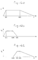
- Fig. 4a, 4b and 4c showmediaally an assumed course of the bound vortix strength over respectively blade and end plates.
- the propeller blade 1 shown in fig. 1a, 1b is at his end (not -shown) attached to the hub (not-shown) and at his other end 2 provided with two end plates 3, 4. These end plates have at the side of the end 2 of the blade a chord length which is smaller than the chord length of that end.
- the end plate 3 is with his front side adjacent to the front edge 5 of the propeller blade, the end plate 4 is with his back side adjacent to the back edge 6 of the propeller blade.
- the end plate 3, 4 are overlapping eachother.
- One and the other is clear from fig. 2.
Landscapes
- Chemical & Material Sciences (AREA)
- Engineering & Computer Science (AREA)
- Combustion & Propulsion (AREA)
- Mechanical Engineering (AREA)
- Ocean & Marine Engineering (AREA)
- Wind Motors (AREA)
- Heterocyclic Compounds That Contain Two Or More Ring Oxygen Atoms (AREA)
- Polyesters Or Polycarbonates (AREA)
- Turbine Rotor Nozzle Sealing (AREA)
- Structures Of Non-Positive Displacement Pumps (AREA)
- Hydraulic Turbines (AREA)
Abstract
Description
- The present invention relates to a ship's propeller provided with propeller blades each having a leading edge and a trailing edge, and with end plates at the end remote from the propeller hub and on both sides of the blade.
- Such a ship's propeller is known from "Patent Abstracts of Japan,
vol 8, no.37, (M-277) (1474). The end plates at the tip of the propeller blades aim to distribute the free vortices coming from the tip of the blade in broadwise direction (= spandirection) of the end plate, so that the kinetic energy losses occured by these free tip vortices remain as low as possible. The end plates however have an important disadvantage. Since they are moved with relatively large speed by the liquid, they intend to a large friction resistance. The energy losses occured by this friction resistance can be so large that the mentioned energy profit is counteracted. It is also known to provide the blades of a ship's propeller at one side of the tip with an end plate. In order to distribute also in this case the tip vortices in the same extension, the width of this endplate must be equal to the sum of the widthes of the plates present on both sides of the tip. Also in this case the friction resistance with respect to the water will be considerable. - The invention aims to provide a propeller with end plates at the blade tips, which has a lower friction resistance with respect to the water than the known propeller.
- This is obtained, in that on the line of the attachment to the blade the end plates have a chord length less than the chord length of the blade end and the lines of attachment of the end plates are overlapping eachother partly, whereby one end plate is extending to the blade leading edge and the other end plate is extending to the blade trailing edge.
- Since the bound vortices in chord direction are distributed over the blade tip, the whole blade tip must be covered by one or two end plates in order to obtain the desired effect.
- According to the invention these vortices are not always distributed over two end plates, such as at the prior art, but substantially over one end plate. The bound vortices present in chord direction at the front side of the blade are namely discharged by the end plate extending to the front edge and the vortices at the back side of the blade by the end plate extending to the back edge. By equalizing the sum of the widthes of the end plates to that of both known end plates or to the width of the single end plate the same favourable distribution of the discharge vortices in broadwise direction is obtained. Since however the width of each end plate according to the inventor is smaller than that of the known single end plate, and its chord length is smaller than the chord length of the known double end plate, a considerable surface decreasement is obtained by the end plates according to the invention with about a
factor 0,4. Since moreover the end plates in the intermediate area of the blade tip overlap eachother, it is obtained that in this area occuring limited vortix strength of the blade tip can be distributed over both end plate halves, in such a way that on the front and back edges of these halves the bound vortix strength can go smoothly to zero to avoid danger of cavitation. - The ship's propeller can be carried out in such a way that on the spot of the attachment the chord lenghts of each end plate is between 90 % and 45 % of that of the blade tip. Preferable however on the spot of the attachment the chord length of each end plate is between 70 % and 45 % of that of the blade tip.
- The smallest surface area of both end plates is obtained if on the spot of the atttachment the chord lengths of both end plates are the same.
- A special favourable effect can be obtained if the form of the propeller is optimalisized in the way as disclosed in International Ship building Progress, part 34, July 1987 Nr. 395, (An optimum screw propeller with end plates) by J.A. Sparenberg and J. de Vries. The there determined optimal circulation distribution with respect to a propeller provided with end plates can now be applied to determine the further form of the end plates according to the invention. The chord lenghts of the end plates are chosen proportional to said optimal circulation distribution, so that danger for cavitation owing to too large underpresures is avoided. In this respect it is remarked that not the position or angle with respect to the flow of front edge and back edge of the end plate halves are important, but the chord lengths of the end plates.
- Finally it is remarked that it is not important whether the front end plate is present at the high pressure or at the low pressure side, provided the back half is present at the other side of the blade.
- The invention will now be explained with reference to an embodiment.
- Fig. 1a, 1b show respectively a side and front view of the end of a propeller blade with end plates.
- Fig. 2 shows the propeller blade according to fig. 1a, 1b perspectively.
- Fig. 3 shows the vortix model of the propeller blade according to fig. 2.
- Fig. 4a, 4b and 4c show grafically an assumed course of the bound vortix strength over respectively blade and end plates.
- The
propeller blade 1 shown in fig. 1a, 1b is at his end (not -shown) attached to the hub (not-shown) and at hisother end 2 provided with twoend plates end 2 of the blade a chord length which is smaller than the chord length of that end. Theend plate 3 is with his front side adjacent to thefront edge 5 of the propeller blade, theend plate 4 is with his back side adjacent to theback edge 6 of the propeller blade. In theintermediate area 7 of theend 2 theend plate - The vortix model shown in figure 3 (seen under the same angle as fig. 2) the propeller blade is indicated by the
bound vortices 8 and theend plates free vortices 11 respectively 12. As known thefree vortices end plates end 2, thevortices 8 present at the front side of the blade are guided away as vortices 9 of theend plate 3, the vortices present on the back side of the blade asvortices 10 of theend plate 4. - In fig. 4 an exampel of an assumed course of the bound vortix strength over the blade tip chord c is indicated and from the front and to the back end seen in the flow direction. In fig. 4b, c their belonging assumed course is indicated of the
bound vortix strength 3 respectively 4 of the front end plate and the back end plate, as well as over the chord of the blade end. At the overlapping of both end plates here assumed between 0,35 c and 0,5 c a lineair course is possible. Further to both end plates equal vortix strength must be discharged. The above mentioned can be obtained if it is satisfied to the following two conditions: - 1e)

- 2e) surface figure 4b = surface figure 4c.
Claims (4)
- Ship's propeller provided with propeller blades each having a leading edge (5) and a trailing edge (6), and with end plates (3,4) at the end (2) remote from the propeller hub and on both sides of the blade, characterized in that on the line of attachment to the blade the end plates have a chord length less than the chord length of the blade end and the lines of attachment of the end plates are overlapping each other partly, whereby one end plate (3) is extending to the blade leading edge and the other end plate (4) is extending to the blade trailing edge.
- Ship's propeller according to claim 1, characterized in that on the line of attachment the chord length of each end plate (3,4) is between 90 % and 45 % of the chord length of the blade tip.
- Ship's propeller according to claim 1 or 2, characterized in that on the line of attachment the chord length of each end plate (3,4) is between 70 % and 45 % of the chord length of the blade tip.
- Ship's propeller according to one of the preceding claims, characterized in that on the line of attachment the chord lengths of both end plates (3,4) are the same.
Applications Claiming Priority (1)
| Application Number | Priority Date | Filing Date | Title |
|---|---|---|---|
| PCT/NL1989/000083 WO1991007313A1 (en) | 1989-11-15 | 1989-11-15 | Ship's propeller |
Publications (2)
| Publication Number | Publication Date |
|---|---|
| EP0500521A1 EP0500521A1 (en) | 1992-09-02 |
| EP0500521B1 true EP0500521B1 (en) | 1994-06-08 |
Family
ID=19853956
Family Applications (1)
| Application Number | Title | Priority Date | Filing Date |
|---|---|---|---|
| EP89913259A Expired - Lifetime EP0500521B1 (en) | 1989-11-15 | 1989-11-15 | Ship's propeller |
Country Status (6)
| Country | Link |
|---|---|
| US (1) | US5312228A (en) |
| EP (1) | EP0500521B1 (en) |
| JP (1) | JPH05501528A (en) |
| AT (1) | ATE106817T1 (en) |
| DE (1) | DE68916040T2 (en) |
| WO (1) | WO1991007313A1 (en) |
Families Citing this family (9)
| Publication number | Priority date | Publication date | Assignee | Title |
|---|---|---|---|---|
| AUPM987994A0 (en) * | 1994-12-06 | 1995-01-05 | Stealth Propulsion International Limited | Improvements to propellers |
| US5405243A (en) * | 1990-12-14 | 1995-04-11 | Stealth Propulsion Pty. Ltd. | Propeller with shrouding ring attached to blade |
| AU726352B2 (en) * | 1994-12-06 | 2000-11-02 | Spi (R & D) Pty. Ltd. | Propeller with annular connecting element interconnecting tips of blades |
| US6000907A (en) * | 1998-08-24 | 1999-12-14 | Bic; Adrian | Fluid-activatable vane for a fluid turbine |
| CN100484831C (en) * | 2000-07-13 | 2009-05-06 | 韩玮 | Fan-type fluid transportation and power propulsion propeller |
| US7007184B2 (en) * | 2000-09-08 | 2006-02-28 | Hewlett-Packard Development Company, L.P. | DIMM connector accomodating sideband signals for battery status and/or control |
| AT507091B1 (en) * | 2008-09-22 | 2010-02-15 | Walter Enthammer | TURBOMACHINE |
| AU2016246617B2 (en) * | 2015-04-08 | 2020-03-19 | Horton, Inc. | Fan blade surface features |
| TWI726684B (en) * | 2020-04-15 | 2021-05-01 | 宏碁股份有限公司 | Fan |
Family Cites Families (11)
| Publication number | Priority date | Publication date | Assignee | Title |
|---|---|---|---|---|
| US1515268A (en) * | 1922-12-27 | 1924-11-11 | Cloverleaf Propeller Company | Propeller |
| GB262349A (en) * | 1926-07-07 | 1926-12-09 | John Gould | Improvements in and relating to screw propellors |
| US1703412A (en) * | 1926-08-09 | 1929-02-26 | Thompson Propeller Securities | Screw propeller |
| US2086307A (en) * | 1935-06-08 | 1937-07-06 | Stewart Archibald Byers | Screw propeller and the like |
| US2104306A (en) * | 1935-07-10 | 1938-01-04 | Mcleod George Harnett | Screw propeller |
| DE899180C (en) * | 1942-10-21 | 1953-12-10 | Gustav Woehrn | Propeller with guide wings |
| ES444150A1 (en) * | 1976-01-08 | 1977-05-16 | Espanoles Astilleros | Marine screw |
| GR71888B (en) * | 1979-11-02 | 1983-08-05 | Espanoles Astilleros | |
| JPS6018599B2 (en) * | 1980-07-10 | 1985-05-11 | 三井造船株式会社 | marine propeller |
| JPS58194689A (en) * | 1982-05-08 | 1983-11-12 | Mitsui Eng & Shipbuild Co Ltd | Manufacture of propeller for ship |
| FR2623569A1 (en) * | 1987-11-19 | 1989-05-26 | Snecma | VANE OF COMPRESSOR WITH DISSYMMETRIC LETTLE LETCHES |
-
1989
- 1989-11-15 US US07/836,013 patent/US5312228A/en not_active Expired - Fee Related
- 1989-11-15 EP EP89913259A patent/EP0500521B1/en not_active Expired - Lifetime
- 1989-11-15 JP JP2500264A patent/JPH05501528A/en active Pending
- 1989-11-15 DE DE68916040T patent/DE68916040T2/en not_active Expired - Fee Related
- 1989-11-15 WO PCT/NL1989/000083 patent/WO1991007313A1/en active IP Right Grant
- 1989-11-15 AT AT89913259T patent/ATE106817T1/en not_active IP Right Cessation
Non-Patent Citations (2)
| Title |
|---|
| Patent Abstracts of Japan, vol. 8, no. 37, (M-277) (1474), 17 February 1984 & JP, A, 58194689 (MITSUI ZOSEN K.K.) 12 November 1983, see abstract; figures 4,5 * |
| Technische Rundschau, vol. 73, no. 10, 3 March 1981, (Bern, CH) S. Iselin: "Flugtechnik. Mehr Auftrieb - weniger Widerstand" page 27, see paragraph "Winglet"; figure 8 * |
Also Published As
| Publication number | Publication date |
|---|---|
| DE68916040T2 (en) | 1995-02-02 |
| WO1991007313A1 (en) | 1991-05-30 |
| ATE106817T1 (en) | 1994-06-15 |
| DE68916040D1 (en) | 1994-07-14 |
| US5312228A (en) | 1994-05-17 |
| EP0500521A1 (en) | 1992-09-02 |
| JPH05501528A (en) | 1993-03-25 |
Similar Documents
| Publication | Publication Date | Title |
|---|---|---|
| EP0500521B1 (en) | Ship's propeller | |
| US7566203B2 (en) | Rotor blade | |
| US4199181A (en) | Snow shovel | |
| PL185777B1 (en) | Trawl board | |
| FR2417640A1 (en) | BLADES FOR TURBINE | |
| NO156502B (en) | ROTOR SHEET WITHOUT PLATFORM | |
| CA1164420A (en) | Fan blade with trailing edge tab | |
| AU2006328698B2 (en) | Propeller | |
| GB2066371A (en) | Marine propeller | |
| CA2048596A1 (en) | High efficiency mixer impeller | |
| US4173938A (en) | Anchors and anchoring system | |
| WO1985002594A1 (en) | Ring propeller | |
| RU1816272C (en) | Hull of ice ship | |
| NO20001511L (en) | Glass-coated bucket for high axial flow | |
| JP2577133B2 (en) | Ship propeller | |
| CA2203816A1 (en) | Propellers | |
| DE69517686D1 (en) | WATER WHEEL FOR FLOWING WATER | |
| US4925412A (en) | Marine drive weed deflector | |
| US4737126A (en) | Paddle | |
| KR102027269B1 (en) | Propulsion efficiency enhancing apparatus | |
| CN109083806B (en) | Wave wing type blade and wind turbine | |
| US1973783A (en) | Stream line stern-post block and rudder assembly | |
| EP0642437B1 (en) | A propeller having optimum efficiency in forward and rearward navigation | |
| US1826026A (en) | Propeller | |
| US5110311A (en) | Air boat slime plow and methods of use |
Legal Events
| Date | Code | Title | Description |
|---|---|---|---|
| PUAI | Public reference made under article 153(3) epc to a published international application that has entered the european phase |
Free format text: ORIGINAL CODE: 0009012 |
|
| 17P | Request for examination filed |
Effective date: 19920224 |
|
| AK | Designated contracting states |
Kind code of ref document: A1 Designated state(s): AT BE CH DE FR GB IT LI LU NL SE |
|
| 17Q | First examination report despatched |
Effective date: 19921026 |
|
| GRAA | (expected) grant |
Free format text: ORIGINAL CODE: 0009210 |
|
| AK | Designated contracting states |
Kind code of ref document: B1 Designated state(s): AT BE CH DE FR GB IT LI LU NL SE |
|
| PG25 | Lapsed in a contracting state [announced via postgrant information from national office to epo] |
Ref country code: NL Effective date: 19940608 |
|
| REF | Corresponds to: |
Ref document number: 106817 Country of ref document: AT Date of ref document: 19940615 Kind code of ref document: T |
|
| ITF | It: translation for a ep patent filed |
Owner name: STUDIO ING. IVO JACOBACCI & C. |
|
| ET | Fr: translation filed | ||
| REF | Corresponds to: |
Ref document number: 68916040 Country of ref document: DE Date of ref document: 19940714 |
|
| NLV1 | Nl: lapsed or annulled due to failure to fulfill the requirements of art. 29p and 29m of the patents act | ||
| EAL | Se: european patent in force in sweden |
Ref document number: 89913259.1 |
|
| PLBE | No opposition filed within time limit |
Free format text: ORIGINAL CODE: 0009261 |
|
| STAA | Information on the status of an ep patent application or granted ep patent |
Free format text: STATUS: NO OPPOSITION FILED WITHIN TIME LIMIT |
|
| 26N | No opposition filed | ||
| PGFP | Annual fee paid to national office [announced via postgrant information from national office to epo] |
Ref country code: FR Payment date: 20001110 Year of fee payment: 12 |
|
| PGFP | Annual fee paid to national office [announced via postgrant information from national office to epo] |
Ref country code: DE Payment date: 20001113 Year of fee payment: 12 Ref country code: CH Payment date: 20001113 Year of fee payment: 12 Ref country code: AT Payment date: 20001113 Year of fee payment: 12 |
|
| PGFP | Annual fee paid to national office [announced via postgrant information from national office to epo] |
Ref country code: GB Payment date: 20001115 Year of fee payment: 12 |
|
| PGFP | Annual fee paid to national office [announced via postgrant information from national office to epo] |
Ref country code: LU Payment date: 20001124 Year of fee payment: 12 |
|
| PGFP | Annual fee paid to national office [announced via postgrant information from national office to epo] |
Ref country code: SE Payment date: 20001127 Year of fee payment: 12 |
|
| PGFP | Annual fee paid to national office [announced via postgrant information from national office to epo] |
Ref country code: BE Payment date: 20010123 Year of fee payment: 12 |
|
| PG25 | Lapsed in a contracting state [announced via postgrant information from national office to epo] |
Ref country code: LU Free format text: LAPSE BECAUSE OF NON-PAYMENT OF DUE FEES Effective date: 20011115 Ref country code: GB Free format text: LAPSE BECAUSE OF NON-PAYMENT OF DUE FEES Effective date: 20011115 Ref country code: AT Free format text: LAPSE BECAUSE OF NON-PAYMENT OF DUE FEES Effective date: 20011115 |
|
| PG25 | Lapsed in a contracting state [announced via postgrant information from national office to epo] |
Ref country code: SE Free format text: LAPSE BECAUSE OF NON-PAYMENT OF DUE FEES Effective date: 20011116 |
|
| PG25 | Lapsed in a contracting state [announced via postgrant information from national office to epo] |
Ref country code: LI Free format text: LAPSE BECAUSE OF NON-PAYMENT OF DUE FEES Effective date: 20011130 Ref country code: CH Free format text: LAPSE BECAUSE OF NON-PAYMENT OF DUE FEES Effective date: 20011130 Ref country code: BE Free format text: LAPSE BECAUSE OF NON-PAYMENT OF DUE FEES Effective date: 20011130 |
|
| REG | Reference to a national code |
Ref country code: GB Ref legal event code: IF02 |
|
| BERE | Be: lapsed |
Owner name: STICHTING VOOR DE TECHNISCHE WETENSCHAPPEN Effective date: 20011130 |
|
| EUG | Se: european patent has lapsed |
Ref document number: 89913259.1 |
|
| PG25 | Lapsed in a contracting state [announced via postgrant information from national office to epo] |
Ref country code: DE Free format text: LAPSE BECAUSE OF NON-PAYMENT OF DUE FEES Effective date: 20020702 |
|
| REG | Reference to a national code |
Ref country code: CH Ref legal event code: PL |
|
| PG25 | Lapsed in a contracting state [announced via postgrant information from national office to epo] |
Ref country code: FR Free format text: LAPSE BECAUSE OF NON-PAYMENT OF DUE FEES Effective date: 20020730 |
|
| REG | Reference to a national code |
Ref country code: FR Ref legal event code: ST |
|
| REG | Reference to a national code |
Ref country code: FR Ref legal event code: ST |
|
| PG25 | Lapsed in a contracting state [announced via postgrant information from national office to epo] |
Ref country code: IT Free format text: LAPSE BECAUSE OF NON-PAYMENT OF DUE FEES;WARNING: LAPSES OF ITALIAN PATENTS WITH EFFECTIVE DATE BEFORE 2007 MAY HAVE OCCURRED AT ANY TIME BEFORE 2007. THE CORRECT EFFECTIVE DATE MAY BE DIFFERENT FROM THE ONE RECORDED. Effective date: 20051115 |