EP0499338A2 - Air vent - Google Patents
Air vent Download PDFInfo
- Publication number
- EP0499338A2 EP0499338A2 EP92200447A EP92200447A EP0499338A2 EP 0499338 A2 EP0499338 A2 EP 0499338A2 EP 92200447 A EP92200447 A EP 92200447A EP 92200447 A EP92200447 A EP 92200447A EP 0499338 A2 EP0499338 A2 EP 0499338A2
- Authority
- EP
- European Patent Office
- Prior art keywords
- valve member
- air vent
- retaining
- valve
- box
- Prior art date
- Legal status (The legal status is an assumption and is not a legal conclusion. Google has not performed a legal analysis and makes no representation as to the accuracy of the status listed.)
- Granted
Links
Images
Classifications
-
- F—MECHANICAL ENGINEERING; LIGHTING; HEATING; WEAPONS; BLASTING
- F24—HEATING; RANGES; VENTILATING
- F24F—AIR-CONDITIONING; AIR-HUMIDIFICATION; VENTILATION; USE OF AIR CURRENTS FOR SCREENING
- F24F13/00—Details common to, or for air-conditioning, air-humidification, ventilation or use of air currents for screening
- F24F13/08—Air-flow control members, e.g. louvres, grilles, flaps or guide plates
- F24F13/18—Air-flow control members, e.g. louvres, grilles, flaps or guide plates specially adapted for insertion in flat panels, e.g. in door or window-pane
Definitions
- This invention relates to an air vent comprising a substantially plate-shaped front member provided with vent openings and guide means, a plate-shaped valve member provided with guide means adapted to cooperate with the guide means of the front member, and with openings located in such a way that the vent openings can be cleared in part or in whole or not at all by sliding the front member and the valve member relative to each other, and an operating mechanism adapted to slide the valve member relative to the front member so as to bring the valve member into an open, closed or partly opened position.
- Such an air vent is known from Netherlands patent application 7201567.
- the vent openings in the front member are sealingly overlapped by the plate surface portions between the vent openings in the valve member, which is in surface-to-surface contact with the front member.
- the valve member consists of a plastics plate, while the front member is made of metal, for instance an aluminum section.
- leakage experienced as draught, may occur owing to bending of the valve member as a result of pressure differences, for instance in the case of wind loads. Further, such leakage can lead to extremely irritating whistling noises.
- the pressure difference that causes the leakage can be removed in such a manner that the air vent closes again.
- the pressure will rapidly become equal to the pressure that previously caused the leakage. This will again lead to leakage and may result in a rattling or trembling air vent, which effect can be aggravated by varying wind loads.
- the object of the invention is to eliminate the above-described disadvantages by considerably reducing the chance of leakages in an air vent of the type described in the preamble.
- the front member and the valve member together with a plate-shaped retaining member form an assembly, in which the valve member is locked between the part of the front member provided with the vent openings and the plate-shaped retaining member which is rigidly mounted relative to the front member and provided with vent openings which are equal to and in alignment with the vent openings in the front member.
- a still further improved seal can be obtained in accordance with a further embodiment of the invention by means of a second assembly consisting of a front member, a valve member and a retaining member, which units have been inter-connected to form a box-like element by means of a material providing a thermal insulation, the two front members forming external surfaces of the box-like element and the operating mechanism bringing the two valve members simultaneously into the open, closed or partly opened position.
- a second assembly consisting of a front member, a valve member and a retaining member, which units have been inter-connected to form a box-like element by means of a material providing a thermal insulation, the two front members forming external surfaces of the box-like element and the operating mechanism bringing the two valve members simultaneously into the open, closed or partly opened position.
- the pressure difference across each of the two valve members is smaller - ideally by half - than the pressure difference in the case of an air vent with only one valve member, so that the chance of leakage is accordingly smaller.
- a further advantage of this embodiment is that by providing a thermal interruption, heat insulation is improved.
- one of the assemblies is detachably and adjustably connected to the box-like element and the other assembly is provided with guide means which enable demounting of the retaining member and the valve member from the box-like element.
- the above-mentioned known air vent comprises guide means in the form of a substantially U-shaped channel extending in the sliding direction of the valve member along two opposite longitudinal edges of the valve member.
- This guide system has proved its merits in the course of time.
- the detachable assembly is demountable in a simple manner by sliding plate-shaped members mounted in the guide out of this guide.
- the other assembly comprises a U-shaped channel which receives both the retaining member and the valve member, the length of one of the legs of the channel being reduced in such a manner that the retaining member and the valve member can be demounted from the mounting formed by the two channels, there being provided locking means cooperating with the one detachable assembly, which locking means in the mounted position of the detachable assembly prevent the retaining member and the valve member from disengaging from the confinement of the channels.
- the non-detachable assembly can also be demounted quickly and simply for cleaning. Cumulatively acting clearances can be compensated for, and hence the sealing effect can again be improved, when, in accordance with a further embodiment of the invention, the locking means consist of a longitudinal flange connected to the front member and/or the retaining member of the one assembly and a strip of resilient material connected to the retaining member of the other assembly.
- pressure differences can be taken up in a stepped manner by virtue of the box-like design.
- This effect can be further improved when, in accordance with a further embodiment of the invention, the longitudinal edge and one of the external walls of the box-like element are provided with pressure equalizing bores, these pressure equalizing bores in the external wall in question terminating in an inner space of the box-like element, which is separated by the longitudinal flange and the strip of resilient material from an inner space which is partly defined by the retaining means provided with vent openings.
- valve members in particular valve members of a relatively great height
- the retaining members of the two assemblies are mutually supported by at least one strip-shaped member which is located within the box-like element and made of a resilient material, which strip-shaped member preferably extends parallel to the sliding direction of the valve members.
- the air vent shown in the drawings comprises a first section 1, which, via a section 2 of a thermally insulating material, for instance a plastics, is coupled with a second section 3 which extends throughout the height of the air vent and, by means of a section 4 similar to section 2, is coupled with a section 5.
- the sections 2, 3, and 5 are made of a relatively stiff and form-retaining material, such as aluminium.
- the section 1 comprises an insertion opening 6, while the section 5 has a retaining flange 7.
- a further section 8 is so designed that it fits between sections 1 and 5 and can be coupled to the section 1 by means of an insertion flange 9.
- Adjacent the point where section 8 adjoins section 5, the former has a flange 10 which at several points is provided with bores for passing therethrough a screw 11 which further extends through bores provided in line therewith in the retaining flange 7 of the section 5.
- a box-like construction is formed which is closed at its ends by end partitions (not shown) which are secured by means of screws 12 in the longitudinal recesses 13 provided for that purpose in the sections 1, 3, and 5.
- the recesses 13 of the section 3 further serve for clampingly mounting a plurality of local retaining strips 14 for receiving a plurality of covering strips 15 extending throughout the width of the air vent to prevent rain from entering.
- the section 8, which is detachably coupled to the sections 1 and 5, comprises a multiplicity of slot-shaped vent openings 16, as shown in Fig. 2. Viewed in the longitudinal direction of the air vent, the ventilation openings are mutually separated by plate surfaces 17 which are slightly wider than the vent openings.
- the drawings show an embodiment which is preferably used for relatively high air vents. To provide for sufficient rigidity, pairs of openings 16 provided above each other are mutually separated by a plate-shaped material bridge 18.
- the section 8 comprises adjacent its two longitudinal edges a rib 19 which forms a guide channel 20 together with a plate portion of the section disposed beyond the vent opening and with a portion of the section that connects that plate portion and the rib.
- a valve member 21 and a retaining member 22 have been slid into the guide channel 20.
- the valve member 21 is in surface-to-surface contact with the part of the section 8 that is provided with vent openings 16, while the retaining member 22 in turn is in surface-to-surface contact with the valve member 21.
- the retaining member 22 has a length which is substantially equal to that of the section 8, the arrangement being such that shifting of the retaining member 22 is prevented by the end partitions (not shown).
- the valve member 21, on the other hand is shorter as viewed in the longitudinal direction thereof, in such a manner that it can be slid back and forth in longitudinal direction by means of a turning knob 23 and a transmission mechanism (not shown).
- the valve member 21 comprises vent openings 24 and the retaining member 22 comprises vent openings 25, which vent openings all have the same dimensions and location as those in the section 8, while in all three elements the same number of vent openings have been provided.
- the vent openings 25 are in alignment with those in the section 8.
- the longitudinal displacement of the valve member 21 by means of the turning knob 23 is defined between an open position wherein the vent openings 24 align with the vent openings 16 and 25, as shown in Fig. 1, and a closed position wherein the vent openings 24 are covered entirely by the plate surfaces 17 on one side and the corresponding plate surfaces of the retaining member 22 on the other side.
- Fig. 2 shows the closed position. It will be clear that between the open and the closed position, a large number of intermediate positions are possible.
- section 3 is provided with vent openings 26 and guide channels 27, in which are mounted a sliding valve member 28 with vent openings 29 and a non-sliding retaining member 30 with vent openings 31.
- the valve member 28 and the valve member 21 can be slid simultaneously by means of the turning knob 23, in such a manner that the vent openings 24 and 29 are simultaneously cleared completely, closed or partly opened.
- section 8 with associated parts can be demounted in a simple manner by unscrewing screws 11, whereafter section 8 can be swung sideways and taken from the section 1 by pulling the insertion flange 9 from the insertion opening 6.
- the retaining member 22 and the valve member 21 can then be demounted in a simple manner by sliding them laterally out of the guide channels 20.
- the section 3 is not demountable in this manner.
- the lower guide channel 27 comprises a rib 32 of reduced dimensions, such that the retaining member 30 and the valve member 28, after removal of section 8, can be detached from the guide channel 27 by pushing it up and swinging it sideways.
- the retaining member 30 and hence the valve member 28 are retained in position by a resilient plastics strip 33 connected to the retaining member, while a hold-down flange 34, which is part of the section 8, bears on this strip 33.
- a plurality of apertures 35 which interconnect the space between the retaining members 25 and 30 and a space 36 between the sections 3, 4, and 5 under the hold-down flange 34.
- This space 36 communicates with the outside air via apertures 37 in the section 3.
- the section 8 further comprises two longitudinally extending receiving channels 38 for an insect wire screen 39 which, therefore, is detachable together with the section 8, for instance for the purpose of cleaning or replacement, and subsequently can be slid out of the receiving channels 38 of the section 8.
- the valve members 21 and 28 as well as retaining members 22 and 30 can be made of plastics so as to give the valve members good sliding properties.
- a strip-shaped member 40 is provided which extends in longitudinal direction and receives support from the two retaining members.
- the strip-shaped member 40 is preferably made of a resilient plastics material, so that independently of the tolerances of the various members, at all times a proper hold-down and relative support can be maintained.
- the strip-shaped member 40 consists of two parts.
- an air vent is provided which in the closed position is always sealed in a particularly effective manner.
- this is accomplished by locking a valve member in surface-to-surface contact between members arranged on opposite sides thereof, whereby the surface-to-surface engagement of the valve member with an adjacent member prevents bending of the valve member as a result of pressure differences.
- the surface-to-surface engagement not only prevents bending but also improves the sealing effect in that the member which the valve member comes in contact with is provided, opposite the vent openings in the valve member, with plate surfaces that overlap those openings.
- a further improvement of the sealing effect is realized by the double design of this improved sealing, whereby, moreover, an enclosed box-like space is formed, which provides for a stepped taking up of a pressure difference across the air vent, i.e., the pressure difference to be taken up is divided between the two seals.
- the sections 3 and 8 are preferably made of a relatively stiff material, for instance aluminium, while the valve members 21 and 29 as well as the retaining members 22 and 30 are preferably made of a plastics material having a low coefficient of friction.
- the resilient strip-shaped member 40 is present, pressing the plastics parts in the direction of the stiffer sections. At the same time, this leads to a closer contact and hence to an improved seal between the various members.
- section 3 could be made of three parts, with the end partitions (not shown) forming a framework together with the top and bottom sections, the two valve assemblies being detachably mounted therein.
- the material bridges 18 could be omitted.
- a strip-shaped member 40 can be provided, which, if so desired, could extend vertically rather than horizontally, i.e., in vertical direction of the air vent.
Abstract
Description
- This invention relates to an air vent comprising a substantially plate-shaped front member provided with vent openings and guide means, a plate-shaped valve member provided with guide means adapted to cooperate with the guide means of the front member, and with openings located in such a way that the vent openings can be cleared in part or in whole or not at all by sliding the front member and the valve member relative to each other, and an operating mechanism adapted to slide the valve member relative to the front member so as to bring the valve member into an open, closed or partly opened position.
- Such an air vent is known from Netherlands patent application 7201567. In the closed position of the air vent, the vent openings in the front member are sealingly overlapped by the plate surface portions between the vent openings in the valve member, which is in surface-to-surface contact with the front member. The valve member consists of a plastics plate, while the front member is made of metal, for instance an aluminum section.
- With such an air vent, leakage, experienced as draught, may occur owing to bending of the valve member as a result of pressure differences, for instance in the case of wind loads. Further, such leakage can lead to extremely irritating whistling noises. In case of leakage, the pressure difference that causes the leakage can be removed in such a manner that the air vent closes again. However, because there is often a considerable space present behind the air vent, after the air vent has closed, the pressure will rapidly become equal to the pressure that previously caused the leakage. This will again lead to leakage and may result in a rattling or trembling air vent, which effect can be aggravated by varying wind loads.
- The object of the invention is to eliminate the above-described disadvantages by considerably reducing the chance of leakages in an air vent of the type described in the preamble.
- This is achieved, in accordance with the invention, in that the front member and the valve member together with a plate-shaped retaining member form an assembly, in which the valve member is locked between the part of the front member provided with the vent openings and the plate-shaped retaining member which is rigidly mounted relative to the front member and provided with vent openings which are equal to and in alignment with the vent openings in the front member. By these features, bending of the valve member, and hence the formation of leakages, is considerably limited by the presence of the retaining member. However, by making the retaining member and the front member of the same design, an additional advantage is gained with respect to the seal, i.e., if pressure differences should lead to bending, then, irrespective of the direction of bending, the valve member is always pushed into closer contact with a part that comprises plate surfaces covering the vent openings in the valve member.
- A still further improved seal can be obtained in accordance with a further embodiment of the invention by means of a second assembly consisting of a front member, a valve member and a retaining member, which units have been inter-connected to form a box-like element by means of a material providing a thermal insulation, the two front members forming external surfaces of the box-like element and the operating mechanism bringing the two valve members simultaneously into the open, closed or partly opened position. Thus, not only the number of seals is doubled, but also the pressure difference between opposite sides of the air vent is taken up in a stepped manner. In other words, the pressure difference across each of the two valve members is smaller - ideally by half - than the pressure difference in the case of an air vent with only one valve member, so that the chance of leakage is accordingly smaller. A further advantage of this embodiment is that by providing a thermal interruption, heat insulation is improved.
- When the air vent is used in practice, the sealing effect can be adversely influenced by dirt. Providing for easy mounting and demounting as well as for easy cleaning of the air vent will contribute to the air vent being maintained in optimum condition. For these reasons it is preferred, and in accordance with a further embodiment of the invention, that one of the assemblies is detachably and adjustably connected to the box-like element and the other assembly is provided with guide means which enable demounting of the retaining member and the valve member from the box-like element.
- The above-mentioned known air vent comprises guide means in the form of a substantially U-shaped channel extending in the sliding direction of the valve member along two opposite longitudinal edges of the valve member. This guide system has proved its merits in the course of time. The detachable assembly is demountable in a simple manner by sliding plate-shaped members mounted in the guide out of this guide. In order that the non-detachable assembly can also be demounted in a simple manner, it is preferred, and in accordance with a further elaboration of the invention, that the other assembly comprises a U-shaped channel which receives both the retaining member and the valve member, the length of one of the legs of the channel being reduced in such a manner that the retaining member and the valve member can be demounted from the mounting formed by the two channels, there being provided locking means cooperating with the one detachable assembly, which locking means in the mounted position of the detachable assembly prevent the retaining member and the valve member from disengaging from the confinement of the channels. Thus, a direct consequence of demounting the detachable assembly is that the non-detachable assembly can also be demounted quickly and simply for cleaning. Cumulatively acting clearances can be compensated for, and hence the sealing effect can again be improved, when, in accordance with a further embodiment of the invention, the locking means consist of a longitudinal flange connected to the front member and/or the retaining member of the one assembly and a strip of resilient material connected to the retaining member of the other assembly.
- As already stated, pressure differences can be taken up in a stepped manner by virtue of the box-like design. This effect can be further improved when, in accordance with a further embodiment of the invention, the longitudinal edge and one of the external walls of the box-like element are provided with pressure equalizing bores, these pressure equalizing bores in the external wall in question terminating in an inner space of the box-like element, which is separated by the longitudinal flange and the strip of resilient material from an inner space which is partly defined by the retaining means provided with vent openings.
- A further safeguard against bending of the valve members, in particular valve members of a relatively great height, can be obtained when, in accordance with a further embodiment of the invention, the retaining members of the two assemblies are mutually supported by at least one strip-shaped member which is located within the box-like element and made of a resilient material, which strip-shaped member preferably extends parallel to the sliding direction of the valve members.
- The air vent according to the invention will now be further explained and illustrated, by way of example only, with reference to the accompanying drawings showing one embodiment of the invention. In said drawings:
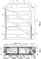
- Fig. 1 is a section of an air vent according to the invention;
- Fig. 2 is a partly cut away view of a part of the air vent shown in Fig. 1.
- The air vent shown in the drawings comprises a
first section 1, which, via asection 2 of a thermally insulating material, for instance a plastics, is coupled with asecond section 3 which extends throughout the height of the air vent and, by means of asection 4 similar tosection 2, is coupled with asection 5. Thesections - The
section 1 comprises an insertion opening 6, while thesection 5 has a retaining flange 7. Afurther section 8 is so designed that it fits betweensections section 1 by means of aninsertion flange 9. Adjacent the point wheresection 8adjoins section 5, the former has aflange 10 which at several points is provided with bores for passing therethrough ascrew 11 which further extends through bores provided in line therewith in the retaining flange 7 of thesection 5. In this manner, a box-like construction is formed which is closed at its ends by end partitions (not shown) which are secured by means of screws 12 in thelongitudinal recesses 13 provided for that purpose in thesections - The
recesses 13 of thesection 3 further serve for clampingly mounting a plurality of local retaining strips 14 for receiving a plurality of coveringstrips 15 extending throughout the width of the air vent to prevent rain from entering. - The
section 8, which is detachably coupled to thesections shaped vent openings 16, as shown in Fig. 2. Viewed in the longitudinal direction of the air vent, the ventilation openings are mutually separated byplate surfaces 17 which are slightly wider than the vent openings. The drawings show an embodiment which is preferably used for relatively high air vents. To provide for sufficient rigidity, pairs ofopenings 16 provided above each other are mutually separated by a plate-shaped material bridge 18. - As will appear from Fig. 1, the
section 8 comprises adjacent its two longitudinal edges arib 19 which forms aguide channel 20 together with a plate portion of the section disposed beyond the vent opening and with a portion of the section that connects that plate portion and the rib. Avalve member 21 and a retainingmember 22 have been slid into theguide channel 20. Thevalve member 21 is in surface-to-surface contact with the part of thesection 8 that is provided withvent openings 16, while the retainingmember 22 in turn is in surface-to-surface contact with thevalve member 21. The retainingmember 22 has a length which is substantially equal to that of thesection 8, the arrangement being such that shifting of the retainingmember 22 is prevented by the end partitions (not shown). Thevalve member 21, on the other hand, is shorter as viewed in the longitudinal direction thereof, in such a manner that it can be slid back and forth in longitudinal direction by means of a turning knob 23 and a transmission mechanism (not shown). - The
valve member 21 comprisesvent openings 24 and theretaining member 22 comprisesvent openings 25, which vent openings all have the same dimensions and location as those in thesection 8, while in all three elements the same number of vent openings have been provided. In the non-sliding retainingmember 22 thevent openings 25 are in alignment with those in thesection 8. The longitudinal displacement of thevalve member 21 by means of the turning knob 23 is defined between an open position wherein thevent openings 24 align with thevent openings vent openings 24 are covered entirely by theplate surfaces 17 on one side and the corresponding plate surfaces of the retainingmember 22 on the other side. Fig. 2 shows the closed position. It will be clear that between the open and the closed position, a large number of intermediate positions are possible. - Like
section 8,section 3 is provided with vent openings 26 andguide channels 27, in which are mounted a slidingvalve member 28 withvent openings 29 and a non-sliding retainingmember 30 withvent openings 31. Thevalve member 28 and thevalve member 21 can be slid simultaneously by means of the turning knob 23, in such a manner that thevent openings - The
section 8 with associated parts can be demounted in a simple manner byunscrewing screws 11, whereaftersection 8 can be swung sideways and taken from thesection 1 by pulling theinsertion flange 9 from theinsertion opening 6. The retainingmember 22 and thevalve member 21 can then be demounted in a simple manner by sliding them laterally out of theguide channels 20. - The
section 3 is not demountable in this manner. To permit demounting of thevalve member 28 and the retainingmember 30, thelower guide channel 27 comprises arib 32 of reduced dimensions, such that the retainingmember 30 and thevalve member 28, after removal ofsection 8, can be detached from theguide channel 27 by pushing it up and swinging it sideways. In mounted position, the retainingmember 30 and hence thevalve member 28, are retained in position by aresilient plastics strip 33 connected to the retaining member, while a hold-down flange 34, which is part of thesection 8, bears on thisstrip 33. - Provided in the hold-
down flange 34 are a plurality ofapertures 35 which interconnect the space between the retainingmembers space 36 between thesections down flange 34. Thisspace 36 communicates with the outside air viaapertures 37 in thesection 3. - The
section 8 further comprises two longitudinally extendingreceiving channels 38 for aninsect wire screen 39 which, therefore, is detachable together with thesection 8, for instance for the purpose of cleaning or replacement, and subsequently can be slid out of thereceiving channels 38 of thesection 8. - It has already been observed that the embodiment shown is a relatively high air vent, which is the reason why
material bridges 18 are provided to increase stiffness. Thevalve members members member 40 is provided which extends in longitudinal direction and receives support from the two retaining members. The strip-shapedmember 40 is preferably made of a resilient plastics material, so that independently of the tolerances of the various members, at all times a proper hold-down and relative support can be maintained. On account of the presence of theinsect screen 39, the strip-shapedmember 40 consists of two parts. - In this way, an air vent is provided which in the closed position is always sealed in a particularly effective manner. In the first place this is accomplished by locking a valve member in surface-to-surface contact between members arranged on opposite sides thereof, whereby the surface-to-surface engagement of the valve member with an adjacent member prevents bending of the valve member as a result of pressure differences. The surface-to-surface engagement not only prevents bending but also improves the sealing effect in that the member which the valve member comes in contact with is provided, opposite the vent openings in the valve member, with plate surfaces that overlap those openings. Thus, although a slight bending leads to the formation of slight gaps on one side of the valve member, it leads to an intensification of the sealing surface-to-surface contact on the other side.
- A further improvement of the sealing effect is realized by the double design of this improved sealing, whereby, moreover, an enclosed box-like space is formed, which provides for a stepped taking up of a pressure difference across the air vent, i.e., the pressure difference to be taken up is divided between the two seals.
- As stated, the
sections valve members members member 40 is present, pressing the plastics parts in the direction of the stiffer sections. At the same time, this leads to a closer contact and hence to an improved seal between the various members. - It will be clear that within the framework of the invention as defined in the appended claims, many modifications and variants are possible. Thus, like
sections section 3 could be made of three parts, with the end partitions (not shown) forming a framework together with the top and bottom sections, the two valve assemblies being detachably mounted therein. Depending on the height of the air vent, the material bridges 18 could be omitted. Even in that case, a strip-shapedmember 40 can be provided, which, if so desired, could extend vertically rather than horizontally, i.e., in vertical direction of the air vent. Reference has been made to metal sections and plastics parts; it will be clear that many other materials and combinations of materials can be used.
Claims (8)
- An air vent comprising a substantially plate-shaped front member provided with vent openings (16; 26) and guide means (20; 27), a plate-shaped valve member (21; 28) provided with guide means adapted to cooperate with the guide means of the front member, and with openings (24; 29) located in such a way that the vent openings can be cleared in part or in whole or not at all by sliding the front member and the valve member relative to each other, and an operating mechanism (23) adapted to slide the valve member relative to the front member so as to bring the valve member into an open, closed or partly opened position, characterized in that the front member and the valve member together with a plate-shaped retaining member (22; 30) form an assembly, in which the valve member is locked between the part of the front member provided with the vent openings and the plate-shaped retaining member which is rigidly mounted relative to the front member and provided with vent openings (25; 31) which are equal to and in alignment with the vent openings in the front member.
- An air vent according to claim 1, characterized by a second assembly consisting of a front member, a valve member and a retaining member, which units have been interconnected to form a box-like element by means of a material (2, 4) providing a thermal interruption, the two front members forming external surfaces of the box-like element and the operating mechanism (23) bringing the two valve members (21, 28) simultaneously into the open, closed or partly opened position.
- An air vent according to claim 2, characterized in that one of the assemblies (8, 21, 22) is detachably and adjustably connected to the box-like element and the other assembly (3, 28, 30) is provided with guide means (33, 34) which enable demounting of the retaining member (30) and the valve member (28) from the box-like element.
- An air vent according to claim 3 and provided with guide means in the form of a substantially U-shaped channel (20) extending in the sliding direction of the valve member (21) along two opposite longitudinal edges of the valve member, characterized in that the other assembly comprises a U-shaped channel (27) which receives both the retaining member (30) and the valve member (28), the length of one of the legs of said channel being reduced in such a manner that the retaining member and the valve member can be disengaged from the confinement of the two channels, there being provided locking means (33, 34) cooperating with the one detachable assembly (8, 21, 22), which locking means in the mounted position of the detachable assembly prevent the retaining member and the valve member from disengaging from the confinement of the channels.
- An air vent according to claim 4, characterized in that the locking means consist of a longitudinal flange (34) connected to the front member and/or the retaining member (22) of the one assembly (8, 21, 22) and a strip (33) of resilient material connected to the retaining member (30) of the other assembly.
- An air vent according to claim 5, characterized in that the longitudinal flange (34) and one of the external walls of the box-like element are provided with pressure equalizing bores (35, 37), these pressure equalizing bores in the external wall in question terminating in an inner space (36) of the box-like element, which is separated by the longitudinal flange and the strip (33) of resilient material from an inner space which is partly defined by the retaining members (22, 30) provided with vent openings (25, 31).
- An air vent according to any one of claims 2-6, characterized in that the retaining members (22, 30) of the two assemblies are mutually supported by at least one strip-shaped member (40) which is located within the box-like element and made of a resilient material.
- An air vent according to claim 7, characterized in that the strip-shaped member (40) extends parallel to the sliding direction of the valve members (21, 28).
Applications Claiming Priority (2)
| Application Number | Priority Date | Filing Date | Title |
|---|---|---|---|
| NL9100271 | 1991-02-15 | ||
| NL9100271A NL9100271A (en) | 1991-02-15 | 1991-02-15 | VENTILATION SLIDE. |
Publications (3)
| Publication Number | Publication Date |
|---|---|
| EP0499338A2 true EP0499338A2 (en) | 1992-08-19 |
| EP0499338A3 EP0499338A3 (en) | 1992-12-30 |
| EP0499338B1 EP0499338B1 (en) | 1996-01-31 |
Family
ID=19858886
Family Applications (1)
| Application Number | Title | Priority Date | Filing Date |
|---|---|---|---|
| EP19920200447 Expired - Lifetime EP0499338B1 (en) | 1991-02-15 | 1992-02-17 | Air vent |
Country Status (3)
| Country | Link |
|---|---|
| EP (1) | EP0499338B1 (en) |
| DE (1) | DE69207926D1 (en) |
| NL (1) | NL9100271A (en) |
Cited By (1)
| Publication number | Priority date | Publication date | Assignee | Title |
|---|---|---|---|---|
| EP2909541A4 (en) * | 2012-09-17 | 2016-07-27 | Swegon Ab | Slide valve for a ventilation device |
Families Citing this family (1)
| Publication number | Priority date | Publication date | Assignee | Title |
|---|---|---|---|---|
| NL191068C (en) * | 1993-01-26 | 1996-05-02 | Zwaan Adrianus J | Ventilation slide. |
Citations (2)
| Publication number | Priority date | Publication date | Assignee | Title |
|---|---|---|---|---|
| FR394337A (en) * | 1908-09-15 | 1909-01-20 | Alexander William Stewart | Improvements in ventilation openings or lanterns |
| NL7201567A (en) * | 1972-02-07 | 1973-08-09 |
-
1991
- 1991-02-15 NL NL9100271A patent/NL9100271A/en not_active Application Discontinuation
-
1992
- 1992-02-17 DE DE69207926T patent/DE69207926D1/en not_active Expired - Lifetime
- 1992-02-17 EP EP19920200447 patent/EP0499338B1/en not_active Expired - Lifetime
Patent Citations (2)
| Publication number | Priority date | Publication date | Assignee | Title |
|---|---|---|---|---|
| FR394337A (en) * | 1908-09-15 | 1909-01-20 | Alexander William Stewart | Improvements in ventilation openings or lanterns |
| NL7201567A (en) * | 1972-02-07 | 1973-08-09 |
Cited By (1)
| Publication number | Priority date | Publication date | Assignee | Title |
|---|---|---|---|---|
| EP2909541A4 (en) * | 2012-09-17 | 2016-07-27 | Swegon Ab | Slide valve for a ventilation device |
Also Published As
| Publication number | Publication date |
|---|---|
| EP0499338B1 (en) | 1996-01-31 |
| DE69207926D1 (en) | 1996-03-14 |
| NL9100271A (en) | 1992-09-01 |
| EP0499338A3 (en) | 1992-12-30 |
Similar Documents
| Publication | Publication Date | Title |
|---|---|---|
| EP0579213B1 (en) | Cabinet for electrical equipment | |
| US5775051A (en) | Frame member for a switchgear cabinet frame | |
| US6062665A (en) | Switchgear cabinet | |
| EP0485349B1 (en) | Section member assembly for making sliding wing window frames | |
| US4736677A (en) | Ventilator assemblies | |
| HU214814B (en) | A sealing arrangement for a glass-carrying window frame | |
| EP0499338A2 (en) | Air vent | |
| US4383519A (en) | Door frame and handle combination | |
| EP0719373B1 (en) | Corner joint assembly | |
| NL2018304B1 (en) | Roof hatch | |
| US4019429A (en) | Ventilator | |
| HU214808B (en) | Side valve ventilator for window | |
| GB2083203A (en) | Ventilation assembly for use with doors or windows | |
| EP0324820A1 (en) | Improved vent for windows and like apertures | |
| GB2134647A (en) | Improvements in or relating to a ventilator | |
| GB2239309A (en) | Window/door ventilators of modular construction | |
| EP0765988A1 (en) | Window system | |
| KR19990087741A (en) | Chiller to secure to control box | |
| US5473842A (en) | Rooftop access system | |
| GB2274511A (en) | Ventilation slide and vent | |
| KR102040442B1 (en) | Window Frame with improved fine dust block effect | |
| EP0327187B1 (en) | A ventilator | |
| JP7358578B2 (en) | curtain wall unit | |
| EP1259685B1 (en) | Roof vents | |
| GB2342154A (en) | Ventilitation device |
Legal Events
| Date | Code | Title | Description |
|---|---|---|---|
| PUAI | Public reference made under article 153(3) epc to a published international application that has entered the european phase |
Free format text: ORIGINAL CODE: 0009012 |
|
| AK | Designated contracting states |
Kind code of ref document: A2 Designated state(s): BE DE FR GB NL |
|
| PUAL | Search report despatched |
Free format text: ORIGINAL CODE: 0009013 |
|
| AK | Designated contracting states |
Kind code of ref document: A3 Designated state(s): BE DE FR GB NL |
|
| 17P | Request for examination filed |
Effective date: 19930204 |
|
| 17Q | First examination report despatched |
Effective date: 19931112 |
|
| GRAA | (expected) grant |
Free format text: ORIGINAL CODE: 0009210 |
|
| AK | Designated contracting states |
Kind code of ref document: B1 Designated state(s): BE DE FR GB NL |
|
| PG25 | Lapsed in a contracting state [announced via postgrant information from national office to epo] |
Ref country code: FR Effective date: 19960131 Ref country code: BE Effective date: 19960131 |
|
| REF | Corresponds to: |
Ref document number: 69207926 Country of ref document: DE Date of ref document: 19960314 |
|
| PG25 | Lapsed in a contracting state [announced via postgrant information from national office to epo] |
Ref country code: GB Effective date: 19960430 |
|
| PG25 | Lapsed in a contracting state [announced via postgrant information from national office to epo] |
Ref country code: DE Effective date: 19960501 |
|
| EN | Fr: translation not filed | ||
| PLBI | Opposition filed |
Free format text: ORIGINAL CODE: 0009260 |
|
| PLBF | Reply of patent proprietor to notice(s) of opposition |
Free format text: ORIGINAL CODE: EPIDOS OBSO |
|
| 26 | Opposition filed |
Opponent name: SIEGENIA-FRANK KG Effective date: 19961025 |
|
| GBPC | Gb: european patent ceased through non-payment of renewal fee |
Effective date: 19960430 |
|
| NLR1 | Nl: opposition has been filed with the epo |
Opponent name: SIEGENIA-FRANK KG |
|
| PLBF | Reply of patent proprietor to notice(s) of opposition |
Free format text: ORIGINAL CODE: EPIDOS OBSO |
|
| PLBO | Opposition rejected |
Free format text: ORIGINAL CODE: EPIDOS REJO |
|
| PLBN | Opposition rejected |
Free format text: ORIGINAL CODE: 0009273 |
|
| STAA | Information on the status of an ep patent application or granted ep patent |
Free format text: STATUS: OPPOSITION REJECTED |
|
| PGFP | Annual fee paid to national office [announced via postgrant information from national office to epo] |
Ref country code: NL Payment date: 19980228 Year of fee payment: 7 |
|
| 27O | Opposition rejected |
Effective date: 19971129 |
|
| NLR2 | Nl: decision of opposition | ||
| PG25 | Lapsed in a contracting state [announced via postgrant information from national office to epo] |
Ref country code: NL Free format text: LAPSE BECAUSE OF NON-PAYMENT OF DUE FEES Effective date: 19990901 |