EP0499305B1 - Improved device for selecting the shift of the rocker arm of the reed operating mechanism of a terry loom - Google Patents
Improved device for selecting the shift of the rocker arm of the reed operating mechanism of a terry loom Download PDFInfo
- Publication number
- EP0499305B1 EP0499305B1 EP92200231A EP92200231A EP0499305B1 EP 0499305 B1 EP0499305 B1 EP 0499305B1 EP 92200231 A EP92200231 A EP 92200231A EP 92200231 A EP92200231 A EP 92200231A EP 0499305 B1 EP0499305 B1 EP 0499305B1
- Authority
- EP
- European Patent Office
- Prior art keywords
- rocker arm
- control lever
- terry
- spring
- push rods
- Prior art date
- Legal status (The legal status is an assumption and is not a legal conclusion. Google has not performed a legal analysis and makes no representation as to the accuracy of the status listed.)
- Expired - Lifetime
Links
Images

Classifications
-
- D—TEXTILES; PAPER
- D03—WEAVING
- D03D—WOVEN FABRICS; METHODS OF WEAVING; LOOMS
- D03D39/00—Pile-fabric looms
- D03D39/22—Terry looms
Definitions
- This invention relates to a device for selecting the shift of the rocker arm of the reed operating mechanism of a terry loom which by not using an electromagnet for moving the pins which couple the control lever to one of the two push rods of said rocker arm and allowing the device to be sealed and hence lubricated in an oil bath, and by using only one operating cam both for operating the lever systems and for said pin movement, results in the achievement of higher operating speeds as required by modern terry looms, a longer life of the device and considerable energy saving, with consequent cost reduction.
- two push rods are generally used hinged to different points of said rocker arm shank, the selection of which of said two push rods is to shift said rocker arm being determined by two electromagnets rigid with said control lever, these being each arranged to magnetically move a pin coupled to the corresponding push rod.
- This known device for selecting the rocker arm shift has a series of drawbacks due substantially to the vibration and wear to which the electromagnets used for moving the coupling pins are subjected; again the time required by said electromagnets for moving the coupling pins limits their efficiency in modern high-speed terry looms.
- the electromagnets also utilize considerable energy in that as they have to produce a considerable movement of the pins, a large magnetic field is required with a consequent large power consumption, even if said pins are made with small dimensions to limit their inertia.
- the object of the present invention is to obviate the aforesaid drawbacks by providing a device for selecting the shift of the rocker arm of the reed operating mechanism of a terry loom, which allows high operating speed, results in very low wear and hence a long life and a considerable energy saving, and in addition allows effective lubrication in an oil bath.
- Said slidable coupling pins are hence housed in suitable grooves in said control lever and opposed by a spring tending to urge them into a passive or retracted position within said groove whereas when in their active or inserted position within said groove they cooperate with a shoulder tooth present at one end of terry height adjustment levers which are idly pivoted on the same axis of rotation as said control lever and have connected to their other end in different positions the ends of said push rods for said rocker arm, to which the push rods are hinged at their other ends. It is apparent that in this manner the vibrations can no longer act on the electromagnets, which are now supported by a fixed element, and that the device can be easily closed hermetically and hence lubricated by an oil bath.
- the device for selecting the shift of the rocker arm of the reed operating mechanism in a terry loom comprising two push rods for shifting said rocker arm from a standard position defined by a return spring to an operating position in which said reed is brought into a retracted or open position to form the terry, said push rods being driven respectively by a control lever which by means of a spring is elastically maintained in contact with the contour of an operating cam driven by the loom drive shaft, and is made to cooperate with one or other of said push rods, is characterised according to the present invention in that said two push rods, hinged to said rocker arm, are also hinged at their other end to mutually different points on an arm of two terry height adjustment levers respectively, which are idly pivoted on the same axis of rotation as said control lever and each have on their other arm a shoulder tooth arranged to cooperate with a corresponding coupling pin slidable within a guide provided in said control lever, in which the pin is retained by a spring in
- the reference numeral 1 indicates the rocker arm of the reed operating mechanism 2 of a terry loom which, being completely known, is represented simply by portions of the two mutually pivoted arms 3 and 4 respectively, the common joint 5 of which is inserted into and guided within the circular-arc slot 6 of said rocker arm 1.
- One end of two push rods 11 and 12 is hinged by the through pin 10 to the rocker arm 1, which is pivoted at 7 and is held by a return spring 8 against a shoulder 9 to assume the standard position corresponding to the reed in the normal beating position, their other end being hinged to a bock 13 and 14 respectively.
- Said blocks 13 and 14 are fixed respectively, by screws 15, to mutually different points on an arm of two terry height adjustment levers 16 and 17 respectively, on the other arm of which there is provided a shoulder tooth 18 and 19 respectively.
- levers 16 and 17 are inserted into the sealed casing 20 of the device and are mounted idly on the shaft 21 which rotates the control lever 22 which is maintained by a spring 23 with its roller 24 elastically in contact with the contour of the operating cam 25 fixed on the shaft 26 driven in the direction of the arrow 27 by the loom drive shaft, and comprises on its arm 22' two guides, 28 and 29 respectively, for two slidable coupling pins 30 and 31 arranged to cooperate respectively with said shoulder teeth 18 and 19 of said levers 16 and 17.
- Said pins 30 and 31 tend to assume a passive or retracted position, ie beyond the influence of the respective teeth 18 and 19, each by the action of a spring 32 acting between an appendix 33 projecting from said control lever 22 and inserted in a slot 34 in said pins, and the rear wall of said slot.
- the coupling pins 30 and 31 also cooperate with the end, 35' and 36' respectively, of two selection levers 35 and 36 pivoted on the same axis 44, their other end, 35'' and 36'' respectively, carrying the armature, 37 and 38 respectively, of two electromagnets 39 and 40 fixed in the casing 20 of the device and energized by an electronic control unit not shown on the figures, to which they are connected by the conductors 41.
- the selection levers 35 and 36 comprise appendices, 42 and 43 respectively, which are maintained in contact with corresponding ledges 45 and 46 on said control lever 22 by the action of springs, 47 and 48 respectively, which act between said ends 35'' and 36'' of the selection levers 35 and 36 and a fixed support 49 in the sense of withdrawing said armatures 37 and 38 from the respective electromagnets 39 and 40.
Landscapes
- Engineering & Computer Science (AREA)
- Textile Engineering (AREA)
- Looms (AREA)
- Treatment Of Fiber Materials (AREA)
Description
- This invention relates to a device for selecting the shift of the rocker arm of the reed operating mechanism of a terry loom which by not using an electromagnet for moving the pins which couple the control lever to one of the two push rods of said rocker arm and allowing the device to be sealed and hence lubricated in an oil bath, and by using only one operating cam both for operating the lever systems and for said pin movement, results in the achievement of higher operating speeds as required by modern terry looms, a longer life of the device and considerable energy saving, with consequent cost reduction.
- It is already known from our preceding U.S. Patent No. 4,406,308 of September 27, 1983, to vary the beating position of the reed of a terry loom from a "closed" or normal position to an "open" or retracted position for terry formation by moving the rocker arm of the reed operating mechanism from its standard position against the action of a return spring, by means of a push rod which is hinged to the shank of said rocker arm and is itself driven by a control lever which is coupled to said push rod and, by means of a spring, is elastically maintained in contact with the contour of an operating cam driven by the loom drive shaft. To achieve two different terry heights without stopping the loom, two push rods are generally used hinged to different points of said rocker arm shank, the selection of which of said two push rods is to shift said rocker arm being determined by two electromagnets rigid with said control lever, these being each arranged to magnetically move a pin coupled to the corresponding push rod.
- This known device for selecting the rocker arm shift has a series of drawbacks due substantially to the vibration and wear to which the electromagnets used for moving the coupling pins are subjected; again the time required by said electromagnets for moving the coupling pins limits their efficiency in modern high-speed terry looms. The electromagnets also utilize considerable energy in that as they have to produce a considerable movement of the pins, a large magnetic field is required with a consequent large power consumption, even if said pins are made with small dimensions to limit their inertia. Finally, the presence of these electromagnets within the region of operation of the coupling pins makes it impossible to seal this region and hence lubricate the pins in an oil bath, as would be required to increase the reliability of the mechanism and to reduce the wear of said pins to a minimum.
- The object of the present invention is to obviate the aforesaid drawbacks by providing a device for selecting the shift of the rocker arm of the reed operating mechanism of a terry loom, which allows high operating speed, results in very low wear and hence a long life and a considerable energy saving, and in addition allows effective lubrication in an oil bath.
- This is substantially attained by moving the slidable coupling pins from an active position to a passive position or vice versa not by electromagnets but by selection levers, one end of which cooperates via a spring with a ledge on the control lever, and the other end of which carries an armature arranged to cooperate with a respective electromagnet the only purpose of which is to retain it, the approach of the armature to the magnet being determined by said cooperation between said ledge on the control lever and said end of the selection lever; in this manner not only is a very low feed power required by the electromagnets with consequent considerable energy saving, but there is absolutely no limitation on operating speed.
- Said slidable coupling pins are hence housed in suitable grooves in said control lever and opposed by a spring tending to urge them into a passive or retracted position within said groove whereas when in their active or inserted position within said groove they cooperate with a shoulder tooth present at one end of terry height adjustment levers which are idly pivoted on the same axis of rotation as said control lever and have connected to their other end in different positions the ends of said push rods for said rocker arm, to which the push rods are hinged at their other ends. It is apparent that in this manner the vibrations can no longer act on the electromagnets, which are now supported by a fixed element, and that the device can be easily closed hermetically and hence lubricated by an oil bath.
- Thus the device for selecting the shift of the rocker arm of the reed operating mechanism in a terry loom, comprising two push rods for shifting said rocker arm from a standard position defined by a return spring to an operating position in which said reed is brought into a retracted or open position to form the terry, said push rods being driven respectively by a control lever which by means of a spring is elastically maintained in contact with the contour of an operating cam driven by the loom drive shaft, and is made to cooperate with one or other of said push rods, is characterised according to the present invention in that said two push rods, hinged to said rocker arm, are also hinged at their other end to mutually different points on an arm of two terry height adjustment levers respectively, which are idly pivoted on the same axis of rotation as said control lever and each have on their other arm a shoulder tooth arranged to cooperate with a corresponding coupling pin slidable within a guide provided in said control lever, in which the pin is retained by a spring in the passive or retracted position, said pin also cooperating with one end of a selection lever the other end of which carries the armature of an electromagnet fixedly mounted in the casing of the device, said selection lever also cooperating with a ledge on said control lever by the action of a spring which tends to withdraw said armature from said electromagnet.
- The invention is further described hereinafter with reference to the accompanying drawings which illustrate a preferred embodiment thereof by way of non-limiting example in that technical or constructional modifications can be made thereto but without leaving the scope of the invention.
- In said drawings:
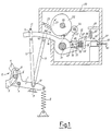
- Figure 1 is a front sectional view of a device for selecting the shift of the rocker arm of the reed operating mechanism of a terry loom, in accordance with the invention;
- Figure 2 is a sectional view from above of the device of Figure 1, to a different scale.
- In the figures the
reference numeral 1 indicates the rocker arm of thereed operating mechanism 2 of a terry loom which, being completely known, is represented simply by portions of the two mutually pivoted arms 3 and 4 respectively, thecommon joint 5 of which is inserted into and guided within the circular-arc slot 6 of saidrocker arm 1. - One end of two
push rods pin 10 to therocker arm 1, which is pivoted at 7 and is held by a return spring 8 against a shoulder 9 to assume the standard position corresponding to the reed in the normal beating position, their other end being hinged to abock blocks screws 15, to mutually different points on an arm of two terry height adjustment levers 16 and 17 respectively, on the other arm of which there is provided ashoulder tooth latter levers casing 20 of the device and are mounted idly on theshaft 21 which rotates thecontrol lever 22 which is maintained by aspring 23 with itsroller 24 elastically in contact with the contour of theoperating cam 25 fixed on theshaft 26 driven in the direction of thearrow 27 by the loom drive shaft, and comprises on its arm 22' two guides, 28 and 29 respectively, for twoslidable coupling pins shoulder teeth levers pins respective teeth control lever 22 and inserted in a slot 34 in said pins, and the rear wall of said slot. Thecoupling pins same axis 44, their other end, 35'' and 36'' respectively, carrying the armature, 37 and 38 respectively, of twoelectromagnets casing 20 of the device and energized by an electronic control unit not shown on the figures, to which they are connected by theconductors 41. Finally, the selection levers 35 and 36 comprise appendices, 42 and 43 respectively, which are maintained in contact withcorresponding ledges control lever 22 by the action of springs, 47 and 48 respectively, which act between said ends 35'' and 36'' of the selection levers 35 and 36 and afixed support 49 in the sense of withdrawing saidarmatures respective electromagnets - The method of operation of such a device is apparent.
- While the contour of the
operating cam 25 presents a protuberance in front of theroller 24 of thecontrol lever 22, this latter is obliged to rotate clockwise about theshaft 21, with corresponding rotation of thecoupling pins electromagnet 39 is energized and retains against itself thearmature 37 of theselection lever 35, which therefore remains in the position shown in Figure 1 and therefore continues to retain thecoupling pin 30 in the active or inserted position against the action of the spring 32, so that said pin cooperates with theshoulder tooth 18 of the terryheight adjustment lever 16 to oblige this latter lever to rotate clockwise about saidshaft 21 and cause therocker arm 1 to rotate anticlockwise about theaxis 7 against the action of its return spring 8 and hence position the loom reed in its open or retracted position to form the terry; or theelectromagnet 39 is not energized so that when thecontrol lever 22 rotates to lower itsledge 45, theselection lever 35 is now obliged by itsspring 47 to rotate anticlockwise about theaxis 44, so enabling the spring 32 of thecoupling pin 30 to move said pin into its passive or retracted position so that, as there is no longer cooperation with saidtooth 18, thelever 16 does not rotate with the result that therocker arm 1, by the effect of the return spring 8, remains in the position of Figure 1 corresponding to the reed in its closed or normal position. It is apparent that the continuous cooperation between theledge 45 of thecontrol lever 22 and theappendix 42 of theselection lever 35 always moves this latter lever into the position shown in Figure 1 each time thecontrol lever 22 is compelled to rotate anticlockwise.
Claims (1)
- A device for selecting the shift of the rocker arm (1) of the reed operating mechanism (2) in a terry loom, comprising two push rods (11, 12) for shifting said rocker arm (1) from a standard position defined by a return spring (8) to an operating position in which said reed is brought into a retracted or open position to form the terry, said push rods 11, 12 being driven respectively by a control lever (22) which by means of a spring (23) is elastically maintained in contact with the contour of an operating cam (25) driven by the loom drive shaft, and is made to cooperate with one or other of said push rods, characterised in that said two push rods (11, 12), hinged to said rocker arm (1), are also hinged at their other end to mutually different points on an arm of two terry height adjustment levers (16, 17) respectively, which are idly pivoted on the same axis (21) of rotation as said control lever (22) and each has on its other arm a shoulder tooth (18, 19) arranged to cooperate with a corresponding coupling pin (30, 31) slidable within a guide (28, 29) provided in said control lever (22), which the pin (30, 31) is retained by a spring (32) in the passive or retracted position, said pin (30, 31) also cooperates with one end of a selection lever (35, 36) the other end of which carries the armature (37, 38) of an electromagnet (39, 40) fixedly mounted in the casing (20) of the device, said selection lever (35, 36) also cooperates with a ledge (45, 46) on said control lever (22) by the action of a spring 47, 48 which tends to withdraw said armature (37, 38) from said electromagnet (39, 40).
Applications Claiming Priority (2)
| Application Number | Priority Date | Filing Date | Title |
|---|---|---|---|
| ITMI910373 | 1991-02-13 | ||
| ITMI910373A IT1244737B (en) | 1991-02-13 | 1991-02-13 | IMPROVED DEVICE FOR THE SELECTION OF THE HANDLING OF THE ROCKER OF THE COMB DRIVE MECHANISM OF A TEXTILE FRAME FOR SPONGE |
Publications (2)
| Publication Number | Publication Date |
|---|---|
| EP0499305A1 EP0499305A1 (en) | 1992-08-19 |
| EP0499305B1 true EP0499305B1 (en) | 1994-12-21 |
Family
ID=11358559
Family Applications (1)
| Application Number | Title | Priority Date | Filing Date |
|---|---|---|---|
| EP92200231A Expired - Lifetime EP0499305B1 (en) | 1991-02-13 | 1992-01-28 | Improved device for selecting the shift of the rocker arm of the reed operating mechanism of a terry loom |
Country Status (8)
| Country | Link |
|---|---|
| US (1) | US5199466A (en) |
| EP (1) | EP0499305B1 (en) |
| JP (1) | JP3220759B2 (en) |
| BR (1) | BR9200479A (en) |
| CS (1) | CS42092A3 (en) |
| DE (1) | DE69200930T2 (en) |
| IT (1) | IT1244737B (en) |
| RU (1) | RU2046855C1 (en) |
Families Citing this family (3)
| Publication number | Priority date | Publication date | Assignee | Title |
|---|---|---|---|---|
| IT1251848B (en) * | 1991-09-23 | 1995-05-26 | Somet Soc Mec Tessile | ELECTROMECHANICAL DEVICE TO COMMAND THE FORMATION MOVEMENTS OF THE CURL IN WEAVING FRAMES OF SPONGE FABRICS |
| IT1264014B (en) * | 1993-04-07 | 1996-09-06 | Nuovo Pignone Spa | PERFECTED MECHANISM FOR TRANSMISSION OF THE COMAND TO SELECT THE COMB STRIKE POSITION IN A SPONGE TEXTILE FRAME |
| DE59708329D1 (en) * | 1997-07-17 | 2002-10-31 | Sulzer Textil Ag Rueti | Device for changing the stop position of a reed and weaving machine with such a device |
Family Cites Families (5)
| Publication number | Priority date | Publication date | Assignee | Title |
|---|---|---|---|---|
| US4099546A (en) * | 1975-12-11 | 1978-07-11 | Nuovo Pignone S.P.A. | Device for varying the beating-up position of the reed of a textile loom for Turkish towelling |
| IT1125861B (en) * | 1979-11-26 | 1986-05-14 | Nuovo Pignone Spa | PERFECTED DEVICE TO VARY THE COMBUSTION POSITION OF THE COMB IN TEXTILE MACHINES FOR SPONGE FABRICS |
| FR2486550A1 (en) * | 1980-07-10 | 1982-01-15 | Alsacienne Constr Meca | Variable reed positioning mechanism for terry fabric loom - incorporating toggle joint permitting selective retraction of reed |
| CH671782A5 (en) * | 1987-01-05 | 1989-09-29 | Ernst Kleiner | |
| FR2662710B1 (en) * | 1990-05-31 | 1992-08-28 | Staubli Sa Ets | ELECTRO-MAGNETIC UNIT FOR THE CONTROL OF RATIERES AND OTHER WEAVING MECHANICS. |
-
1991
- 1991-02-13 IT ITMI910373A patent/IT1244737B/en active IP Right Grant
-
1992
- 1992-01-28 DE DE69200930T patent/DE69200930T2/en not_active Expired - Fee Related
- 1992-01-28 EP EP92200231A patent/EP0499305B1/en not_active Expired - Lifetime
- 1992-01-30 US US07/828,235 patent/US5199466A/en not_active Expired - Lifetime
- 1992-02-07 JP JP05607392A patent/JP3220759B2/en not_active Expired - Fee Related
- 1992-02-12 RU SU925010903A patent/RU2046855C1/en active
- 1992-02-12 BR BR929200479A patent/BR9200479A/en not_active Application Discontinuation
- 1992-02-12 CS CS92420A patent/CS42092A3/en unknown
Also Published As
| Publication number | Publication date |
|---|---|
| ITMI910373A0 (en) | 1991-02-13 |
| DE69200930D1 (en) | 1995-02-02 |
| US5199466A (en) | 1993-04-06 |
| DE69200930T2 (en) | 1995-04-20 |
| JP3220759B2 (en) | 2001-10-22 |
| EP0499305A1 (en) | 1992-08-19 |
| CS42092A3 (en) | 1992-09-16 |
| RU2046855C1 (en) | 1995-10-27 |
| IT1244737B (en) | 1994-08-08 |
| BR9200479A (en) | 1992-10-20 |
| JPH04316638A (en) | 1992-11-09 |
| ITMI910373A1 (en) | 1992-08-13 |
Similar Documents
| Publication | Publication Date | Title |
|---|---|---|
| US4461325A (en) | Electromagnetic device for controlling dobbies and other weaving systems | |
| US5803133A (en) | Selvage-forming device for a power loom | |
| GB2041990A (en) | Electromagnetic jacquard attachment | |
| EP0499305B1 (en) | Improved device for selecting the shift of the rocker arm of the reed operating mechanism of a terry loom | |
| RU2091640C1 (en) | High speed rotary carriage | |
| RU2067135C1 (en) | Rotating dobby with electronic automatic control system | |
| US5918645A (en) | Catch configurations for the pivot arms of a rotary dobby | |
| JP3086930B2 (en) | Super high speed rotary dobby controller | |
| US5090457A (en) | Electro magnetic weft selection device | |
| EP0144874B1 (en) | Jacquard mechanism | |
| US5029618A (en) | Electromagnetic control device for a dobby | |
| US3941161A (en) | Jacquard reversing mechanism for looms | |
| GB2063933A (en) | Terry motions | |
| US5125435A (en) | Electro-magnetic cassette unit for controlling dobbies | |
| PT837957E (en) | DEVICE FOR THE SELECTION OF HOOKS IN A TEAR DEBUX MECHANISM | |
| US6478055B2 (en) | Pulleyless shed-forming device for a weaving machine | |
| US4442869A (en) | Apparatus for the optical retention of the two reciprocatingly driven control elements of the shed forming arrangement associated with a loom | |
| RU1794116C (en) | Weaving loom | |
| EP0556490A1 (en) | Improved device for driving the ring levers controlling the keys of a high-speed rotary dobby | |
| US4869297A (en) | Device for forming a selvedge or selvedges on woven cloth | |
| US3895658A (en) | Paper card reading apparatus in a dobby machine | |
| CA1098419A (en) | Shuttle drive arrangement | |
| JP3242987B2 (en) | Warp selection device for looms | |
| JPS59199841A (en) | Shuttle driving method in loom | |
| SU875549A1 (en) | Device for retaining linear electric motor secondary element |
Legal Events
| Date | Code | Title | Description |
|---|---|---|---|
| PUAI | Public reference made under article 153(3) epc to a published international application that has entered the european phase |
Free format text: ORIGINAL CODE: 0009012 |
|
| AK | Designated contracting states |
Kind code of ref document: A1 Designated state(s): BE CH DE ES FR GB LI NL |
|
| DX | Miscellaneous (deleted) | ||
| 17P | Request for examination filed |
Effective date: 19921009 |
|
| 17Q | First examination report despatched |
Effective date: 19940530 |
|
| GRAA | (expected) grant |
Free format text: ORIGINAL CODE: 0009210 |
|
| AK | Designated contracting states |
Kind code of ref document: B1 Designated state(s): BE CH DE ES FR GB LI NL |
|
| PG25 | Lapsed in a contracting state [announced via postgrant information from national office to epo] |
Ref country code: NL Effective date: 19941221 Ref country code: FR Effective date: 19941221 Ref country code: ES Free format text: THE PATENT HAS BEEN ANNULLED BY A DECISION OF A NATIONAL AUTHORITY Effective date: 19941221 |
|
| REF | Corresponds to: |
Ref document number: 69200930 Country of ref document: DE Date of ref document: 19950202 |
|
| EN | Fr: translation not filed | ||
| NLV1 | Nl: lapsed or annulled due to failure to fulfill the requirements of art. 29p and 29m of the patents act | ||
| PLBE | No opposition filed within time limit |
Free format text: ORIGINAL CODE: 0009261 |
|
| STAA | Information on the status of an ep patent application or granted ep patent |
Free format text: STATUS: NO OPPOSITION FILED WITHIN TIME LIMIT |
|
| 26N | No opposition filed | ||
| PG25 | Lapsed in a contracting state [announced via postgrant information from national office to epo] |
Ref country code: GB Effective date: 19960128 |
|
| GBPC | Gb: european patent ceased through non-payment of renewal fee |
Effective date: 19960128 |
|
| PGFP | Annual fee paid to national office [announced via postgrant information from national office to epo] |
Ref country code: CH Payment date: 20040106 Year of fee payment: 13 |
|
| PGFP | Annual fee paid to national office [announced via postgrant information from national office to epo] |
Ref country code: DE Payment date: 20040108 Year of fee payment: 13 |
|
| PGFP | Annual fee paid to national office [announced via postgrant information from national office to epo] |
Ref country code: BE Payment date: 20040216 Year of fee payment: 13 |
|
| PG25 | Lapsed in a contracting state [announced via postgrant information from national office to epo] |
Ref country code: LI Free format text: LAPSE BECAUSE OF NON-PAYMENT OF DUE FEES Effective date: 20050131 Ref country code: CH Free format text: LAPSE BECAUSE OF NON-PAYMENT OF DUE FEES Effective date: 20050131 Ref country code: BE Free format text: LAPSE BECAUSE OF NON-PAYMENT OF DUE FEES Effective date: 20050131 |
|
| BERE | Be: lapsed |
Owner name: *NUOVOPIGNONE INDUSTRIE MECCANICHE E FONDERIA S.P. Effective date: 20050131 |
|
| PG25 | Lapsed in a contracting state [announced via postgrant information from national office to epo] |
Ref country code: DE Free format text: LAPSE BECAUSE OF NON-PAYMENT OF DUE FEES Effective date: 20050802 |
|
| REG | Reference to a national code |
Ref country code: CH Ref legal event code: PL |
|
| BERE | Be: lapsed |
Owner name: *NUOVOPIGNONE INDUSTRIE MECCANICHE E FONDERIA S.P. Effective date: 20050131 |