EP0499272B1 - Nichtlinearoptisches Element und seine Verwendung - Google Patents
Nichtlinearoptisches Element und seine Verwendung Download PDFInfo
- Publication number
- EP0499272B1 EP0499272B1 EP92102511A EP92102511A EP0499272B1 EP 0499272 B1 EP0499272 B1 EP 0499272B1 EP 92102511 A EP92102511 A EP 92102511A EP 92102511 A EP92102511 A EP 92102511A EP 0499272 B1 EP0499272 B1 EP 0499272B1
- Authority
- EP
- European Patent Office
- Prior art keywords
- nonlinear optical
- optical element
- transparent
- microsphere
- transparent microsphere
- Prior art date
- Legal status (The legal status is an assumption and is not a legal conclusion. Google has not performed a legal analysis and makes no representation as to the accuracy of the status listed.)
- Expired - Lifetime
Links
- 230000003287 optical effect Effects 0.000 title claims description 263
- 239000004005 microsphere Substances 0.000 claims description 219
- 230000005284 excitation Effects 0.000 claims description 62
- 239000000758 substrate Substances 0.000 claims description 55
- 239000007787 solid Substances 0.000 claims description 33
- 239000002245 particle Substances 0.000 claims description 27
- 239000013543 active substance Substances 0.000 claims description 24
- 239000000126 substance Substances 0.000 claims description 19
- 238000000034 method Methods 0.000 claims description 16
- 229920000620 organic polymer Polymers 0.000 claims description 15
- 238000002347 injection Methods 0.000 claims description 10
- 239000007924 injection Substances 0.000 claims description 10
- 239000007771 core particle Substances 0.000 claims description 8
- 230000008878 coupling Effects 0.000 claims description 6
- 238000010168 coupling process Methods 0.000 claims description 6
- 238000005859 coupling reaction Methods 0.000 claims description 6
- 230000002708 enhancing effect Effects 0.000 claims description 4
- 230000001678 irradiating effect Effects 0.000 claims 8
- XEEYBQQBJWHFJM-UHFFFAOYSA-N Iron Chemical compound [Fe] XEEYBQQBJWHFJM-UHFFFAOYSA-N 0.000 claims 2
- 229910052742 iron Inorganic materials 0.000 claims 1
- 238000009877 rendering Methods 0.000 claims 1
- 239000011521 glass Substances 0.000 description 24
- VOFUROIFQGPCGE-UHFFFAOYSA-N nile red Chemical compound C1=CC=C2C3=NC4=CC=C(N(CC)CC)C=C4OC3=CC(=O)C2=C1 VOFUROIFQGPCGE-UHFFFAOYSA-N 0.000 description 15
- VYPSYNLAJGMNEJ-UHFFFAOYSA-N silicon dioxide Inorganic materials O=[Si]=O VYPSYNLAJGMNEJ-UHFFFAOYSA-N 0.000 description 14
- 239000000975 dye Substances 0.000 description 13
- 239000000463 material Substances 0.000 description 13
- 239000004793 Polystyrene Substances 0.000 description 12
- 239000010410 layer Substances 0.000 description 12
- 229920002223 polystyrene Polymers 0.000 description 12
- 238000005259 measurement Methods 0.000 description 11
- 239000013307 optical fiber Substances 0.000 description 11
- 239000002131 composite material Substances 0.000 description 10
- 230000000694 effects Effects 0.000 description 9
- 230000006870 function Effects 0.000 description 9
- 239000000853 adhesive Substances 0.000 description 7
- 230000001070 adhesive effect Effects 0.000 description 7
- 150000002500 ions Chemical class 0.000 description 7
- 239000007788 liquid Substances 0.000 description 7
- -1 methyl methacrylate) Chemical compound 0.000 description 7
- 229920000642 polymer Polymers 0.000 description 6
- 229910052761 rare earth metal Inorganic materials 0.000 description 6
- 239000004065 semiconductor Substances 0.000 description 6
- 239000005368 silicate glass Substances 0.000 description 6
- 230000002269 spontaneous effect Effects 0.000 description 6
- 239000005365 phosphate glass Substances 0.000 description 5
- 239000010453 quartz Substances 0.000 description 5
- 230000004044 response Effects 0.000 description 5
- 150000001875 compounds Chemical class 0.000 description 4
- 238000010586 diagram Methods 0.000 description 4
- 238000010521 absorption reaction Methods 0.000 description 3
- 230000003321 amplification Effects 0.000 description 3
- 230000015572 biosynthetic process Effects 0.000 description 3
- 230000008859 change Effects 0.000 description 3
- 238000010276 construction Methods 0.000 description 3
- 230000007423 decrease Effects 0.000 description 3
- 239000011159 matrix material Substances 0.000 description 3
- 238000002844 melting Methods 0.000 description 3
- 230000008018 melting Effects 0.000 description 3
- 239000000203 mixture Substances 0.000 description 3
- 238000012544 monitoring process Methods 0.000 description 3
- 239000000178 monomer Substances 0.000 description 3
- 238000003199 nucleic acid amplification method Methods 0.000 description 3
- 229920003229 poly(methyl methacrylate) Polymers 0.000 description 3
- 239000004926 polymethyl methacrylate Substances 0.000 description 3
- 238000003980 solgel method Methods 0.000 description 3
- 239000010409 thin film Substances 0.000 description 3
- 125000000391 vinyl group Chemical group [H]C([*])=C([H])[H] 0.000 description 3
- MYRTYDVEIRVNKP-UHFFFAOYSA-N 1,2-Divinylbenzene Chemical compound C=CC1=CC=CC=C1C=C MYRTYDVEIRVNKP-UHFFFAOYSA-N 0.000 description 2
- YCKRFDGAMUMZLT-UHFFFAOYSA-N Fluorine atom Chemical compound [F] YCKRFDGAMUMZLT-UHFFFAOYSA-N 0.000 description 2
- 108010010803 Gelatin Proteins 0.000 description 2
- SXRSQZLOMIGNAQ-UHFFFAOYSA-N Glutaraldehyde Chemical compound O=CCCCC=O SXRSQZLOMIGNAQ-UHFFFAOYSA-N 0.000 description 2
- BAPJBEWLBFYGME-UHFFFAOYSA-N Methyl acrylate Chemical compound COC(=O)C=C BAPJBEWLBFYGME-UHFFFAOYSA-N 0.000 description 2
- PPBRXRYQALVLMV-UHFFFAOYSA-N Styrene Chemical compound C=CC1=CC=CC=C1 PPBRXRYQALVLMV-UHFFFAOYSA-N 0.000 description 2
- 239000011149 active material Substances 0.000 description 2
- MWPLVEDNUUSJAV-UHFFFAOYSA-N anthracene Chemical compound C1=CC=CC2=CC3=CC=CC=C3C=C21 MWPLVEDNUUSJAV-UHFFFAOYSA-N 0.000 description 2
- 239000011324 bead Substances 0.000 description 2
- 238000004364 calculation method Methods 0.000 description 2
- 229920000547 conjugated polymer Polymers 0.000 description 2
- 239000013078 crystal Substances 0.000 description 2
- 239000006063 cullet Substances 0.000 description 2
- 238000000295 emission spectrum Methods 0.000 description 2
- 239000007850 fluorescent dye Substances 0.000 description 2
- 229910052731 fluorine Inorganic materials 0.000 description 2
- 239000011737 fluorine Substances 0.000 description 2
- 239000012634 fragment Substances 0.000 description 2
- 239000000499 gel Substances 0.000 description 2
- 239000008273 gelatin Substances 0.000 description 2
- 229920000159 gelatin Polymers 0.000 description 2
- 235000019322 gelatine Nutrition 0.000 description 2
- 235000011852 gelatine desserts Nutrition 0.000 description 2
- 150000002484 inorganic compounds Chemical class 0.000 description 2
- 229910010272 inorganic material Inorganic materials 0.000 description 2
- 230000015654 memory Effects 0.000 description 2
- QEFYFXOXNSNQGX-UHFFFAOYSA-N neodymium atom Chemical compound [Nd] QEFYFXOXNSNQGX-UHFFFAOYSA-N 0.000 description 2
- PLDDOISOJJCEMH-UHFFFAOYSA-N neodymium oxide Inorganic materials [O-2].[O-2].[O-2].[Nd+3].[Nd+3] PLDDOISOJJCEMH-UHFFFAOYSA-N 0.000 description 2
- 230000005693 optoelectronics Effects 0.000 description 2
- 238000012545 processing Methods 0.000 description 2
- 239000001044 red dye Substances 0.000 description 2
- CVAVMIODJQHEEH-UHFFFAOYSA-O rhodamine B(1+) Chemical compound C=12C=CC(=[N+](CC)CC)C=C2OC2=CC(N(CC)CC)=CC=C2C=1C1=CC=CC=C1C(O)=O CVAVMIODJQHEEH-UHFFFAOYSA-O 0.000 description 2
- 239000000377 silicon dioxide Substances 0.000 description 2
- 238000012360 testing method Methods 0.000 description 2
- 229920002554 vinyl polymer Polymers 0.000 description 2
- UEQIIHOZXGDENJ-UHFFFAOYSA-N 19-(diethylamino)-10-oxa-3-azapentacyclo[12.8.0.02,11.04,9.015,20]docosa-1(14),2(11),3,5,8,12,15(20),16,18,21-decaen-7-one Chemical compound O1C2=CC(=O)C=CC2=NC2=C1C=CC1=C2C=CC2=C1C=CC=C2N(CC)CC UEQIIHOZXGDENJ-UHFFFAOYSA-N 0.000 description 1
- GOLORTLGFDVFDW-UHFFFAOYSA-N 3-(1h-benzimidazol-2-yl)-7-(diethylamino)chromen-2-one Chemical compound C1=CC=C2NC(C3=CC4=CC=C(C=C4OC3=O)N(CC)CC)=NC2=C1 GOLORTLGFDVFDW-UHFFFAOYSA-N 0.000 description 1
- 239000004342 Benzoyl peroxide Substances 0.000 description 1
- OMPJBNCRMGITSC-UHFFFAOYSA-N Benzoylperoxide Chemical compound C=1C=CC=CC=1C(=O)OOC(=O)C1=CC=CC=C1 OMPJBNCRMGITSC-UHFFFAOYSA-N 0.000 description 1
- 229910021591 Copper(I) chloride Inorganic materials 0.000 description 1
- 229910052691 Erbium Inorganic materials 0.000 description 1
- 229910052693 Europium Inorganic materials 0.000 description 1
- 229910001218 Gallium arsenide Inorganic materials 0.000 description 1
- 241000199695 Harmonia <beetle> Species 0.000 description 1
- 230000005374 Kerr effect Effects 0.000 description 1
- VVQNEPGJFQJSBK-UHFFFAOYSA-N Methyl methacrylate Chemical compound COC(=O)C(C)=C VVQNEPGJFQJSBK-UHFFFAOYSA-N 0.000 description 1
- 229910052779 Neodymium Inorganic materials 0.000 description 1
- 239000006087 Silane Coupling Agent Substances 0.000 description 1
- PJANXHGTPQOBST-VAWYXSNFSA-N Stilbene Natural products C=1C=CC=CC=1/C=C/C1=CC=CC=C1 PJANXHGTPQOBST-VAWYXSNFSA-N 0.000 description 1
- XTXRWKRVRITETP-UHFFFAOYSA-N Vinyl acetate Chemical compound CC(=O)OC=C XTXRWKRVRITETP-UHFFFAOYSA-N 0.000 description 1
- 238000000862 absorption spectrum Methods 0.000 description 1
- 150000001252 acrylic acid derivatives Chemical class 0.000 description 1
- 125000002723 alicyclic group Chemical group 0.000 description 1
- PNEYBMLMFCGWSK-UHFFFAOYSA-N aluminium oxide Inorganic materials [O-2].[O-2].[O-2].[Al+3].[Al+3] PNEYBMLMFCGWSK-UHFFFAOYSA-N 0.000 description 1
- 238000004458 analytical method Methods 0.000 description 1
- 238000013459 approach Methods 0.000 description 1
- 235000019400 benzoyl peroxide Nutrition 0.000 description 1
- 230000005540 biological transmission Effects 0.000 description 1
- 238000007664 blowing Methods 0.000 description 1
- VYXSBFYARXAAKO-WTKGSRSZSA-N chembl402140 Chemical compound Cl.C1=2C=C(C)C(NCC)=CC=2OC2=C\C(=N/CC)C(C)=CC2=C1C1=CC=CC=C1C(=O)OCC VYXSBFYARXAAKO-WTKGSRSZSA-N 0.000 description 1
- 238000006243 chemical reaction Methods 0.000 description 1
- 239000003795 chemical substances by application Substances 0.000 description 1
- 229910001430 chromium ion Inorganic materials 0.000 description 1
- 239000011248 coating agent Substances 0.000 description 1
- 239000011247 coating layer Substances 0.000 description 1
- 238000000576 coating method Methods 0.000 description 1
- 229910052681 coesite Inorganic materials 0.000 description 1
- 238000004891 communication Methods 0.000 description 1
- 229920001577 copolymer Polymers 0.000 description 1
- OXBLHERUFWYNTN-UHFFFAOYSA-M copper(I) chloride Chemical compound [Cu]Cl OXBLHERUFWYNTN-UHFFFAOYSA-M 0.000 description 1
- 229910052906 cristobalite Inorganic materials 0.000 description 1
- 238000002109 crystal growth method Methods 0.000 description 1
- 125000000113 cyclohexyl group Chemical group [H]C1([H])C([H])([H])C([H])([H])C([H])(*)C([H])([H])C1([H])[H] 0.000 description 1
- 230000003247 decreasing effect Effects 0.000 description 1
- 238000011161 development Methods 0.000 description 1
- 239000010432 diamond Substances 0.000 description 1
- 229910003460 diamond Inorganic materials 0.000 description 1
- 238000009826 distribution Methods 0.000 description 1
- 230000005672 electromagnetic field Effects 0.000 description 1
- 239000000839 emulsion Substances 0.000 description 1
- 238000007720 emulsion polymerization reaction Methods 0.000 description 1
- UHESRSKEBRADOO-UHFFFAOYSA-N ethyl carbamate;prop-2-enoic acid Chemical compound OC(=O)C=C.CCOC(N)=O UHESRSKEBRADOO-UHFFFAOYSA-N 0.000 description 1
- 230000001747 exhibiting effect Effects 0.000 description 1
- 239000012530 fluid Substances 0.000 description 1
- 239000005303 fluorophosphate glass Substances 0.000 description 1
- 239000012456 homogeneous solution Substances 0.000 description 1
- 229920001519 homopolymer Polymers 0.000 description 1
- 230000003100 immobilizing effect Effects 0.000 description 1
- 230000001939 inductive effect Effects 0.000 description 1
- 230000010365 information processing Effects 0.000 description 1
- 239000003999 initiator Substances 0.000 description 1
- 238000011835 investigation Methods 0.000 description 1
- 239000000990 laser dye Substances 0.000 description 1
- 238000004519 manufacturing process Methods 0.000 description 1
- 150000002734 metacrylic acid derivatives Chemical class 0.000 description 1
- 229910021645 metal ion Inorganic materials 0.000 description 1
- 229910044991 metal oxide Inorganic materials 0.000 description 1
- 150000004706 metal oxides Chemical class 0.000 description 1
- 238000002156 mixing Methods 0.000 description 1
- 238000012986 modification Methods 0.000 description 1
- 230000004048 modification Effects 0.000 description 1
- KDEDDPRZIDYFOB-UHFFFAOYSA-N n-methyl-n-phenylnitramide Chemical compound [O-][N+](=O)N(C)C1=CC=CC=C1 KDEDDPRZIDYFOB-UHFFFAOYSA-N 0.000 description 1
- 239000012860 organic pigment Substances 0.000 description 1
- 125000002524 organometallic group Chemical group 0.000 description 1
- 229920000553 poly(phenylenevinylene) Polymers 0.000 description 1
- 229920000548 poly(silane) polymer Polymers 0.000 description 1
- 229920000015 polydiacetylene Polymers 0.000 description 1
- 238000006116 polymerization reaction Methods 0.000 description 1
- 229920001296 polysiloxane Polymers 0.000 description 1
- 229920000123 polythiophene Polymers 0.000 description 1
- 235000019353 potassium silicate Nutrition 0.000 description 1
- 230000000644 propagated effect Effects 0.000 description 1
- 238000005086 pumping Methods 0.000 description 1
- 238000011084 recovery Methods 0.000 description 1
- 238000012827 research and development Methods 0.000 description 1
- 230000000630 rising effect Effects 0.000 description 1
- 150000003839 salts Chemical class 0.000 description 1
- SBIBMFFZSBJNJF-UHFFFAOYSA-N selenium;zinc Chemical compound [Se]=[Zn] SBIBMFFZSBJNJF-UHFFFAOYSA-N 0.000 description 1
- 230000008054 signal transmission Effects 0.000 description 1
- NTHWMYGWWRZVTN-UHFFFAOYSA-N sodium silicate Chemical compound [Na+].[Na+].[O-][Si]([O-])=O NTHWMYGWWRZVTN-UHFFFAOYSA-N 0.000 description 1
- 239000002904 solvent Substances 0.000 description 1
- 238000001228 spectrum Methods 0.000 description 1
- 238000004528 spin coating Methods 0.000 description 1
- 238000007447 staining method Methods 0.000 description 1
- PJANXHGTPQOBST-UHFFFAOYSA-N stilbene Chemical compound C=1C=CC=CC=1C=CC1=CC=CC=C1 PJANXHGTPQOBST-UHFFFAOYSA-N 0.000 description 1
- 235000021286 stilbenes Nutrition 0.000 description 1
- 229910052682 stishovite Inorganic materials 0.000 description 1
- 210000000352 storage cell Anatomy 0.000 description 1
- 125000001424 substituent group Chemical group 0.000 description 1
- 239000002344 surface layer Substances 0.000 description 1
- 239000004094 surface-active agent Substances 0.000 description 1
- 230000008961 swelling Effects 0.000 description 1
- 230000001360 synchronised effect Effects 0.000 description 1
- 238000003786 synthesis reaction Methods 0.000 description 1
- 238000012546 transfer Methods 0.000 description 1
- 238000002834 transmittance Methods 0.000 description 1
- 229910052905 tridymite Inorganic materials 0.000 description 1
- 238000007740 vapor deposition Methods 0.000 description 1
- 230000010356 wave oscillation Effects 0.000 description 1
Images


Classifications
-
- G—PHYSICS
- G02—OPTICS
- G02F—OPTICAL DEVICES OR ARRANGEMENTS FOR THE CONTROL OF LIGHT BY MODIFICATION OF THE OPTICAL PROPERTIES OF THE MEDIA OF THE ELEMENTS INVOLVED THEREIN; NON-LINEAR OPTICS; FREQUENCY-CHANGING OF LIGHT; OPTICAL LOGIC ELEMENTS; OPTICAL ANALOGUE/DIGITAL CONVERTERS
- G02F1/00—Devices or arrangements for the control of the intensity, colour, phase, polarisation or direction of light arriving from an independent light source, e.g. switching, gating or modulating; Non-linear optics
- G02F1/35—Non-linear optics
- G02F1/355—Non-linear optics characterised by the materials used
-
- G—PHYSICS
- G02—OPTICS
- G02F—OPTICAL DEVICES OR ARRANGEMENTS FOR THE CONTROL OF LIGHT BY MODIFICATION OF THE OPTICAL PROPERTIES OF THE MEDIA OF THE ELEMENTS INVOLVED THEREIN; NON-LINEAR OPTICS; FREQUENCY-CHANGING OF LIGHT; OPTICAL LOGIC ELEMENTS; OPTICAL ANALOGUE/DIGITAL CONVERTERS
- G02F1/00—Devices or arrangements for the control of the intensity, colour, phase, polarisation or direction of light arriving from an independent light source, e.g. switching, gating or modulating; Non-linear optics
- G02F1/01—Devices or arrangements for the control of the intensity, colour, phase, polarisation or direction of light arriving from an independent light source, e.g. switching, gating or modulating; Non-linear optics for the control of the intensity, phase, polarisation or colour
- G02F1/0126—Opto-optical modulation, i.e. control of one light beam by another light beam, not otherwise provided for in this subclass
-
- G—PHYSICS
- G02—OPTICS
- G02F—OPTICAL DEVICES OR ARRANGEMENTS FOR THE CONTROL OF LIGHT BY MODIFICATION OF THE OPTICAL PROPERTIES OF THE MEDIA OF THE ELEMENTS INVOLVED THEREIN; NON-LINEAR OPTICS; FREQUENCY-CHANGING OF LIGHT; OPTICAL LOGIC ELEMENTS; OPTICAL ANALOGUE/DIGITAL CONVERTERS
- G02F1/00—Devices or arrangements for the control of the intensity, colour, phase, polarisation or direction of light arriving from an independent light source, e.g. switching, gating or modulating; Non-linear optics
- G02F1/35—Non-linear optics
- G02F1/353—Frequency conversion, i.e. wherein a light beam is generated with frequency components different from those of the incident light beams
- G02F1/3536—Four-wave interaction
- G02F1/3538—Four-wave interaction for optical phase conjugation
-
- H—ELECTRICITY
- H01—ELECTRIC ELEMENTS
- H01S—DEVICES USING THE PROCESS OF LIGHT AMPLIFICATION BY STIMULATED EMISSION OF RADIATION [LASER] TO AMPLIFY OR GENERATE LIGHT; DEVICES USING STIMULATED EMISSION OF ELECTROMAGNETIC RADIATION IN WAVE RANGES OTHER THAN OPTICAL
- H01S3/00—Lasers, i.e. devices using stimulated emission of electromagnetic radiation in the infrared, visible or ultraviolet wave range
- H01S3/10—Controlling the intensity, frequency, phase, polarisation or direction of the emitted radiation, e.g. switching, gating, modulating or demodulating
- H01S3/10084—Frequency control by seeding
- H01S3/10092—Coherent seed, e.g. injection locking
-
- H—ELECTRICITY
- H01—ELECTRIC ELEMENTS
- H01S—DEVICES USING THE PROCESS OF LIGHT AMPLIFICATION BY STIMULATED EMISSION OF RADIATION [LASER] TO AMPLIFY OR GENERATE LIGHT; DEVICES USING STIMULATED EMISSION OF ELECTROMAGNETIC RADIATION IN WAVE RANGES OTHER THAN OPTICAL
- H01S3/00—Lasers, i.e. devices using stimulated emission of electromagnetic radiation in the infrared, visible or ultraviolet wave range
- H01S3/14—Lasers, i.e. devices using stimulated emission of electromagnetic radiation in the infrared, visible or ultraviolet wave range characterised by the material used as the active medium
- H01S3/16—Solid materials
- H01S3/168—Solid materials using an organic dye dispersed in a solid matrix
Definitions
- the present invention relates to a nonlinear optical element and more particularly to the one which can be used as devices in light(electromagnetic wave-) related fields, that is, optical and optoelectronic fields. Also, the present invention relates to uses of such a nonlinear optical element.
- Various methods have been used for controlling the form of such materials with view to fabricating devices therefrom, which methods include (1) crystal growth methods in which large single crystals, single thin film crystals, etc. are formed; and (2) thin film formation methods such as Langmuir-Brodget (BL) method, vacuum vapor deposition method, spin-coating method, and the like.
- BL Langmuir-Brodget
- One approach for solving the aforementioned problem is to utilize spherical microcavities made of conventional nonlinear optical materials, exhibiting light confinement effect, with view to inducing nonlinear optical phenomena at low thresholds.
- one or more transparent microspheres constituting the nonlinear optical element can individually operate as a single discrete microcavity, which makes it possible to utilize a high Q value due to the light confinement effect and allow nonlinear optical effects to be exhibited with a very weak light.
- Arrangement of a plurality of transparent microspheres to connect them in series and fixation of them to a substrate enable coupling of lights entrapped in the respective transparent microspheres, allowing exhibition of great nonlinear optical effects.
- the nonlinear optical element is constituted by at least one transparent microsphere and the or each microsphere is very small, it is possible to apply the nonlinear optical element of the present invention to micro optical systems such as optical fibers directly. This can give rise to nonlinear optical elements which are of high densities and integrated types, and have compact structures.
- a nonlinear optical element having transparent microspheres arranged and fixed two-dimensionally on a substrate not only can constitute a phase conjugate mirror utilized in compensating for phase distortion in surface light emission lasers or marking transmittance or in image processing but also can be used as an optical logic element, an optical storage cell, an optical rectifier element, an optical transistor, an optical switch or the like, especially an all optical element.
- a nonlinear optical element of the present invention having transparent microspheres which contain different luminous dyes, and are uniformly arranged on a substrate enables color analysis or image synthesis of phase conjugate image by image formation in the arranged transparent microspheres with a color image signal light and selective irradiation of lights with wavelengths matching those of the absorption peaks of the dyes contained in the respective microspheres.
- the nonlinear optical element of the present invention is mechanically stable and easy to be handled since it has a construction that one or more transparent microspheres are fixed to the substrate, and therefore is practically very useful.
- the nonlinear optical element of the present invention has a substrate and a nonlinear optical unit fixed thereto.
- the nonlinear optical unit includes at least one transparent microsphere, at least one nonlinear optical active region associated with the transparent microsphere(s) and at least one light reflection region associated with the transparent microsphere(s).
- the nonlinear optical active region(s) is or are present in the inside of the transparent microsphere(s).
- the or each transparent microsphere are partially made of a nonlinear optical active substance system.
- the or transparent microsphere(s) may be partially doped with a nonlinear optical active substance.
- the light reflection region is in the inside of the transparent microsphere.
- the surface of the or each transparent microsphere serves as the interface of the light reflection region and the light confined in the transparent microsphere propagates within the microsphere and reflects on the interface.
- the nonlinear optical unit used in the nonlinear optical element of the present invention may be composed of one or more transparent microspheres made of a nonlinear optical active substance system.
- the transparent microspheres used in the present invention may have a refractive index of at least 1.4, preferably at least 1.45 so that they can exhibit excellent optical characteristics.
- the transparent microspheres used in the present invention must have a transparency high enough to exhibit light confinement effect, and it is practically preferred that they have a transparency of 5X10cm -1 or less.
- the transparency is defined as ⁇ in I o exp(- ⁇ L), intensity of transmitted light when excitation light having an intensity of incident light I o passes through a medium having a thickness of L cm.
- the transparent microsphere or microspheres have a nonlinear optical coefficient ⁇ 3 of 10 -13 esu or larger.
- the nonlinear optical active substance system constituting the nonlinear optical active region may be composed of a single nonlinear optical active substance or material, or a plurality of nonlinear optical active substances or materials.
- the transparent microsphere is made exclusively of a polymer or polymers having nonlinear optical characteristics, the polymer or polymers must meet the condition of the third harmonic nonlinear optical coefficient ⁇ 3 described above.
- the transparent microsphere is made of a blend of a matrix material and a nonlinear optical active substance
- the transparent microspheres which can be used in the present invention may have a diameter of, usually 1 to 200 ⁇ m, and preferably 10 to 100 ⁇ m. If the diameter of the microsphere is less than 1 ⁇ m, it is difficult to confine light into the microsphere so that whispering gallery modes will become difficult to appear to decrease Q value (quality factor) representative of the efficiency of confinement or entrapping of light. On the contrary, if the transparent microsphere has a diameter of above 100 ⁇ m, a large number of modes are confined, which makes the optical information complicated.
- the microsphere may preferably be a regular sphere in shape and have a smooth surface such that there are on the surface no depressions or protrusions or cracks, flaws or any other types of irregularities of a depth or height by 1/10 time or more, preferably 1/20 time or more, as large as the wavelength of the irradiated light.
- coefficient of variation of particle diameter of the transparent microspheres is preferably 5 % or less. If the coefficient of variation of particle diameter is within that range, light confinement modes in the respective microspheres are rendered uniform, and the microspheres can be used under equivalent conditions.
- coefficient of variation standard deviation mean particle diameter x 100 (%)
- coefficient of variation standard deviation mean particle diameter x 100 (%)
- the particle diameter of each particle is measured under microscope.
- the transparent microsphere may be made of, for example, (1) an organic polymer, (2) an inorganic substance, or (3) a composite substance composed of an inorganic substance and an organic polymer.
- Examples of the organic polymer or the one constituting the composite substance include homopolymers and copolymers of styrene, methacrylates (such as methyl methacrylate), acrylates (such as methyl acrylate), vinyl acetate, divinylbenzene, vinyl monomers having an alicyclic group (such as a cyclohexyl group), and conjugated polymers such as polydiacetylenes, polythiophenes, poly-p-phenylenevinylenes, etc.
- the conjugated polymers can be used advantageously when the nonlinear optical part is to be constituted with only organic polymer(s).
- the transparent microspheres made of the organic polymer may be bilayered ones of which the core particle is made of a first organic polymer and the surface thereof is covered with a second organic polymer different from the first one.
- the nonlinear optical active substance may be contained in either one of or both of the core particle and the surface layer (outer shell).
- the transparent microspheres made of the organic polymer can be prepared by conventional emulsion polymerization. Also, they can be prepared by seed polymerization of the microspheres thus obtained in which a monomer is polymerized on the transparent microspheres while they are being swollen in a solvent in the presence of a swelling aid or the like.
- inorganic optical materials made of metal oxides such as various glasses, alumina, silica, etc. can be used.
- the nonlinear optical active part made of the inorganic substance is used as a light source for lasing with a wavelength of 1,000 nm or more
- the inorganic substance made of a glass containing rare earth element ions includes, for example, glasses such as silicate glass (SiO 2 ), phosphate glass (P 2 O 5 ), or fluorophosphate glass (LiFAl(PO 3 ) 3 ), in which generally 10 % by weight or less, usually about 3 % by weight, of oxide of the aforementioned rare earth elements is contained.
- the glasses can be made spherical by a blowing method including melting the raw composition at about 1,500°C, generally at 800 to 900°C with adding a melting aid, to prepare glass cullet, shattering the cullet, classifying the resulting glass fragments, and melting the glass fragments again in flame to obtain transparent microspheres made of glass.
- the transparent microspheres made of a composite substance may be those of which the composite substance is composed of the inorganic substance and the organic polymer.
- the transparent microspheres may comprise core particles which have a regular sphere and are made of an inorganic substance or an organic polymer, and an outer layer or shell formed on the surfaces of the core particles, the layer or shell being made of an organic polymer or an inorganic substance, respectively.
- a solid medium comprised by a nonlinear optical substance may be coated as the outermost layer on the surface of the microsphere made of the inorganic substance or organic polymer to thereby constitute a part of the composite transparent microsphere.
- the surfaces of glass beads can be treated with a silane coupling agent having a vinyl group, and the aforementioned vinyl monomer is polymerized in the presence of a radical initiator such as benzoyl peroxide on the surfaces of the treated glass beads to obtain composite transparent microspheres.
- the composite transparent microspheres which can be used in the present invention also include transparent microspheres made of polysiloxane, polysilanes, or the like having one or more organic substituent groups prepared by a conventional sol-gel method, and any transparent microspheres whose surfaces are treated with the aforementioned sol-gel method.
- the nonlinear optical active substances in the nonlinear optical active substance system used in the present invention can be selected from those which can be excited with laser beam used as incident light.
- the nonlinear optical active part is made of a nonlinear optical active substance and a matrix material, it is preferred to use the nonlinear optical active substances having compatibilities with the matrix material.
- the nonlinear optical active substance system may be selected from those substances which can emit strong fluorescent light, for example, organic fluorescent dyes such as Rhodamine 6G, nile red, and coumarin, the aforementioned rare earth element ions, lasing materials composed of semiconductors of the families III-V type, e.g., GaAs, and the like.
- nonlinear optical element When the nonlinear optical element is directed for uses other than lasing, there can be used, in addition to the aforementioned lasing materials, third nonlinear optical materials including organic conjugate type compounds having low molecular weights such as stilbene, and methylnitroaniline, the aforementioned conjugate polymers, compound semiconductors of the families II-VI type, e.g., CdS, CdS x Se 1-x , CuCl, ZnSe, etc. as well as organometallic complexes, complex salts, organic dyes, organic pigments, and the like.
- third nonlinear optical materials including organic conjugate type compounds having low molecular weights such as stilbene, and methylnitroaniline, the aforementioned conjugate polymers, compound semiconductors of the families II-VI type, e.g., CdS, CdS x Se 1-x , CuCl, ZnSe, etc. as well as organometallic complexes, complex salts, organic dyes, organic pigments
- the nonlinear optical active substance system has a transparency and a nonlinear optical susceptibility high enough in a wavelength region of the laser beam used.
- the nonlinear optical active substances in the wavelength region of 400 to 900 nm, it is preferred to select the nonlinear optical active substances from the organic polymers or conjugate polymers, blended with organic dyes, the aforementioned organic conjugate compounds having low molecular weights, the aforementioned II-VI type compound semiconductors, and the like.
- inorganic compounds such as glasses containing rare earth element ions are preferred.
- the nonlinear optical element of the present invention when intended to be used as a laser, first a desired lasing wavelength region is set up and then a suitable nonlinear optical active substance system is selected taking into consideration what excitation beam is to be used.
- a suitable nonlinear optical active substance system for example, in the lasing region of 400 to 900 nm, substances having a high fluorescing intensity such as laser dyes, anthracene, etc., are used preferably.
- transparent microspheres made of a silicate glass containing Nd 3+ while for lasing in the 1054 nm band, transparent microspheres made of a phosphate glass containing Nd 3+ are preferred.
- the transparent microspheres described above can individually function as a nonlinear optical element and exhibit third harmonic nonlinear optical phenomena, and hence the nonlinear optical element of the present invention may comprise a single transparent microsphere fixed to a substrate.
- two or more transparent microspheres may be arranged on a substrate unidimensionally, two-dimensionally or three-dimensionally and fixed thereto, thus providing a nonlinear optical element suitable for various applications.
- the nonlinear optical element of the present invention comprises a nonlinear optical unit fixed to a substrate.
- a solid medium may be used as the fixing means for fixing or immobilizing.
- the solid medium has a refractive index which is lower than that of the transparent microsphere, and difference in the refractive index between the solid medium and the transparent microsphere is 0.05 or more, and preferably 0.1 or more. If the difference in the refractive index between the two is less than 0.05, the coefficient of light confinement into the microsphere decreases, thus failing to give rise to practically acceptable nonlinear optical characteristics sufficient for nonlinear optical elements.
- the solid medium is selected from adhesives, organic polymers, inorganic compounds, and the like.
- adhesives organic polymers, inorganic compounds, and the like.
- fluorine-containing photohardenable materials urethane acrylate, gelatin cured with glutaraldehyde, polymethyl methacrylate, water glass, a glass-like product obtained by a sol-gel method.
- the solid medium may also be a gel such as hydrous gel so far as it is non-fluid or immobile.
- the solid medium itself can constitute the substrate.
- the solid medium may contact or cover either the entire surface of the or each transparent microsphere or a part thereof when the or each transparent microsphere is fixed therewith to the substrate or immobilized therewith. In both cases, it is necessary that a light path is secured through which the excitation beam is passed to the surface of the or each transparent microsphere and also an output light path is secured through which nonlinear optical phenomena exhibited are monitored or transmitted to the outside of the transparent microsphere(s).
- the or each transparent microsphere may be fixed or immobilized mechanically by clamping the transparent microsphere(s) with two substrates.
- an individual transparent microsphere When fixing the transparent microsphere(s), an individual transparent microsphere may be caught and arranged on the substrate with a diamond stylus, a manipulator or the like, or a single transparent microsphere or a population of transparent microspheres may be moved and arranged appropriately on the substrate by means of pressure of a laser beam. A thin film of the transparent microspheres formed on a gas-liquid interface or a liquid-liquid interface may be transferred onto the substrate.
- the substrate may be patterned using a resist material before fixing the transparent microsphere thereto. Provision of the patterns makes it possible to fix the transparent microsphere or microspheres at predetermined position(s) easily and with certainty.
- the substrate may be formed with a groove or micro depressions for receiving the or each transparent microsphere in order to facilitating to securely hold the transparent microsphere(s).
- a plurality of the transparent microspheres may be arranged unidimensionally, two-dimensionally or three-dimensionally, in a non-connected (noncontacting) state to each other, or in a state in which some part or a required number of transparent microspheres are connected (contacting) to each other directly or indirectly via an optical medium such as an optical fiber, followed by fixing to obtain nonlinear optical elements having various functions corresponding to various purposes.
- CW lasers continuous wave lasers
- laser beams from such lasers have a wavelength within the range of, usually 0.2 to 2 ⁇ m, and preferably 0.4 to 1.2 ⁇ m.
- the excitation beam which may be monochromatic or a mixture of two or more rays having different wavelengths, can be selected appropriately depending on the type of the transparent microsphere constituting the nonlinear optical element of the present invention, and the nonlinear optical effects to be obtained.
- the power of the excitation beam must be high enough to cause a laser emission when a conventional nonlinear optical element is used for lasing, only a weak excitation beam as high as 100 pJ or less, for example, can cause nonlinear optical phenomena sufficiently.
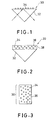
- Figs. 1 to 7 illustrate specific modes of fixation of the transparent microspheres
- Fig. 1 is a cross sectional view showing a nonlinear optical element, illustrating propagation of light therein
- Fig. 2 is a cross sectional view showing a nonlinear optical element according to another example
- Fig. 3 is a cross sectional view showing a nonlinear optical element according to still another example
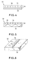
- Fig. 4 is a cross sectional of view showing a nonlinear optical element according to yet another example
- Fig. 5 is a cross sectional view showing a nonlinear optical element according to other examples
- Fig. 6 is a schematic perspective view showing a nonlinear optical element according to a further example
- Fig. 7 is a schematic perspective view showing a nonlinear optical element according to still further example.
- a nonlinear optical element 30 has a substrate 32 in the form of a triangular prism of glass, on which a plurality of transparent microspheres 34 are arranged and fixed or immobilized thereon with a solid medium (not shown) made of an adhesive.
- the transparent microspheres are arranged spaced apart from each other.
- the nonlinear optical element 30 has the substrate 32 and a plurality of the transparent microspheres 34 dispersed in a solid medium 36 three-dimensionally. The transparent microspheres 34 and the solid medium 36 together form a solid layer 38, which is fixed to the substrate 32.
- Fig. 1 the substrate 32 in the form of a triangular prism of glass, on which a plurality of transparent microspheres 34 are arranged and fixed or immobilized thereon with a solid medium (not shown) made of an adhesive.
- the transparent microspheres are arranged spaced apart from each other.
- the nonlinear optical element 30 has the substrate 32 and a plurality of the transparent microspheres 34 dispersed in
- the nonlinear optical element 30 is constituted solely by the solid layer 38 which has the transparent microspheres 34 dispersed in the solid medium 36 three-dimensionally.
- the solid layer also serves as the substrate 30.
- the nonlinear optical element 30 has the substrate 32 made of glass and the solid layer 38 fixed to the substrate 32 and composed of the transparent microspheres 32 dispersed unidimensionally in the solid medium 36.
- the nonlinear optical element 30 has the substrate 32 made of glass, onto which the solid layer 38 is fixed.
- the solid layer 38 includes the solid medium 36 having unidimensionally dispersed therein transparent microspheres 34.
- the excitation beam propagates in the substrate 32 while repeating reflections as indicated by arrows.
- the transparent microspheres are arranged in the solid layer 38 such that they are spaced apart from the interface between the substrate 32 and the solid medium 38 at a distance on the order of 1/2 to 2 times the wavelength of the excitation beam used.
- the nonlinear optical element 30 has the substrate 32 which is formed with a groove 40 of a V form in cross section on upper surface thereof.
- the transparent microspheres 32 are fitted in the groove 40 and fixed therein with a solid medium or adhesive (not shown).
- the transparent microspheres 32 are arranged at a predetermined distance one from another, generally 1/2 to 2 times as long as the wavelength of the excitation beam used, e.g., 0.3 to 0.5 ⁇ m.
- the nonlinear optical element 30 has the substrate 32 formed on its upper surface with a plurality of micro depressions 42, e.g. those with spherical surfaces having a curvature preferably the same as that of the spherical surface of the transparent microsphere to be fixed.
- the transparent microspheres 32 are placed in the respective depressions and fixed with a solid medium (not shown).
- the shape of the substrate 32 is not limited to triangular prism or the like.
- the transparent microspheres may also be connected and fixed directly to optical media such as optical fibers.
- the transparent microspheres may be arranged in contact with each other, spaced apart one from another at a distance or pitch 1/2 to 2 times the wavelength of the excitation beam used, or spaced apart one from another at a distance or pitch more than 2 times the wavelength of the excitation beam used.
- One of these arrangements is selected depending on the purpose for which the nonlinear optical element is used.
- the nonlinear optical element of the present invention exhibit third harmonia nonlinear optical effects and hence can be used for various applications. More particularly, the element of the invention can be used in the following applications:
- the microsphere was fixed onto a surface of a quartz glass substrate with an adhesive (solid medium: gelatin hardened with glutaraldehyde, refractive index: 1.5) to obtain a nonlinear optical element.
- Fig. 8 is a block diagram showing an apparatus for measuring nonlinear optical characteristics
- Fig. 9 is a partial cross sectional view showing the nonlinear optical element and an optical fiber optically connected thereto.
- the nonlinear optical element thus obtained was measured for its nonlinear optical characteristics using the apparatus shown in Fig. 8.
- an apparatus 50 for measuring the nonlinear optical characteristics of the nonlinear optical element 30 comprises a stereoscopic microscope 52 equipped with a camera 54.
- the nonlinear optical element 30 above is placed so that it is in the field of view of the microscope 52.
- the apparatus 50 includes a light source or excimer laser 56 optically connected to a dye laser 58 which produces a laser beam for excitation.
- the excitation beam is reflected at a mirror 60 and passed through a lens 62 and introduced into the transparent microsphere 34 fixed on the glass substrate 32.
- An emergent beam from the nonlinear optical element 30 is received by an optical fiber 64, passed through a lens 66 and led to a spectroscope 68, which is connected to a Box-Kerr integrator 70.
- the integrator 7C is connected to a computer 72.
- the excitation beam is split through beam splitters 74 and 76, respectively, and passed through pin photodiodes 78 and 80, respectively, each of which is connected to the Box-Kerr integrator 70.
- the transparent microsphere 34 is fixed onto the substrate 32 with an adhesive or solid medium (not shown), and a tip 64a of the optical fiber 64 is arranged under the lower surface of the substrate 32 so that the tip 64a opposes the transparent microsphere.
- the modes hereafter, referred to as "whispering gallery modes" are typical patterns evidencing light confinement effect at certain wavelengths in the nonlinear optical element of this example.
- various transparent polystyrene microspheres with different particle diameters i.e., 1, 5, 10, 20, 30, 40, 60, and 90 ⁇ m, respectively, were prepared in the same manner as above and were used.
- the transparent microspheres were fixed to respective substrates to obtain four nonlinear optical elements.
- a regular spherical, transparent microsphere made of polystyrene containing Nile Red and having a particle diameter of 40 ⁇ m was prepared in the same manner as in Example 1 and fixed onto a substrate made of glass in the same manner as in Example 1 to obtain a nonlinear optical element.
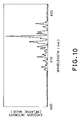
- Figs. 12, 13 and 14 illustrate results obtained are illustrated in Figs. 12, 13 and 14.
- Fig. 12 illustrates dependence of the light emission intensity of the nonlinear optical element on the intensity of excitation beam
- Fig. 13 illustrates dependence of the ratio of the light emission intensity in the lasing wavelength region to that in spontaneous fluorescing wavelength region of the nonlinear optical element cn the intensity of the excitation beam
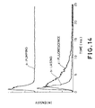
- Fig. 14 illustrates time response characteristics of light emission by the nonlinear optical element.
- Fig. 12 From Fig. 12, it can be seen that sharp light emission peaks appear in a wavelength region of 600 to 630 nm according as the intensity of the excitation beam increases.
- the light emission peaks are considered to correspond to lasing of whispering gallery modes judging from the dependence on the intensity of the excitation beam illustrated in Fig. 13 and the time response characteristics illustrated in Fig. 14.
- I L designates the intensity of light emission in lasing wavelength region and IF the intensity of emission light in spontaneous emission of spontaneous fluorescing wavelength region.
- curves c and b indicate time response characteristics of light emissions at excitation beam intensities of below the threshold and of above the threshold, respectively.
- Curve c shows a typical profile for spontaneous emission while curve b is characterized by an abrupt rising following the pumping beam a and a short relaxation time frcm which it is concluded that the curve b shows a profile of lasing.
- the nonlinear optical element of the present invention can function as a laser beam source even when it has only one transparent microsphere fixed to the substrate. Therefore, by arranging the transparent microsphere two- or three-dimensionally and fixing them, the nonlinear optical element of the present invention can be used as two- or three-dimensional array for plane emission lasers and optical computers.
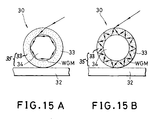
- Figs. 15A and 15B are each a cross sectional view of the nonlinear optical element of the present invention.
- a transparent microsphere 34 made of glass (refractive index: 1.9) and having a particle diameter of 40 ⁇ m was coated with polymethyl methacrylate 33 containing Nile Red to obtain a composite transparent microsphere 35, which then was fixed onto a quartz glass substrate 32 to form a nonlinear optical element 30 of the present invention.
- the nonlinear optical element 30 of the invention as shown in Fig. 15B was fabricated by coating the transparent microsphere 34 made of glass (refractive index: 1.5) and having a particle diameter of 40 ⁇ m with polystyrene 33 containing Nile Red, and fixing the resulting composite transparent microsphere 35 onto the quartz glass substrate 32.
- Example 1 A nonlinear optical element having the same construction as that of Example 1 was fabricated in the same manner as in Example 1.
- an excitation beam with a wavelength of 530 nm to establish laser emission modes in a wavelength region of 600 to 630 nm, and then a control beam (second excitation beam) with a wave number (wavelength) equal to that of a specified lasing region was irradiated additionally.
- a control beam (second excitation beam) with a wave number (wavelength) equal to that of a specified lasing region was irradiated additionally.
- Fig. 16 is a block diagram showing an apparatus for measuring nonlinear optical characteristics of the element of the present invention.
- the apparatus shown in Fig. 16 has substantially the same construction as that of the apparatus shown in Fig. 8. Differences are that a dye laser (Rhodamine 610) 59 for emitting a control beam is provided and the pin photodiode 80 is omitted in the apparatus shown in Fig. 16.
- the dye lasers 58 and 59 are connected parallel to each other and the beam from the excimer laser 56 is split by the beam splitter 76 and introduced into respective dye lasers.
- the beam emergent from the dye laser 59 can be combined to the beam emergent from the dye laser 58 through the mirror 60 and half mirror 76. Same or like parts or components are indicated by same reference numerals and detailed description thereof is omitted here.
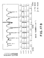
- Figs. 17A and 17B An excitation beam with a wavelength of 530 nm was irradiated to the nonlinear optical element, with or without irradiation of a control beam, and light emission modes and whispering gallery modes (estimated from numerical calculation) were obtained. Results obtained are illustrated in Figs. 17A and 17B.
- Fig. 17A illustrates relationship between light emission mode and whispering gallery mode when the nonlinear optical element of the present invention was irradiated only with the excitation beam with a wavelength of 530 nm.
- sharp peaks are observed at wave numbers in the range between 16150 and 16550 (wavelengths: 619 and 604 nm) .
- Fig. 17A sharp peaks are observed at wave numbers in the range between 16150 and 16550 (wavelengths: 619 and 604 nm) .
- FIG. 17B illustrates relationship between reduced laser emission intensity at a wave number of 16390 (wavelength: 610 nm) and whispering gallery mode when the nonlinear optical element of the present invention was irradiated with the same excitation beam with a wavelength of 530 nm together with a control beam from the Rhodamine 610 laser 59 with continuously changing the wave number of the control beam from 16150 to 16550 cm -1 (wavelength: 619 to 604 nm).
- the locked modes modes of reduced laser emission intensities, as indicated by the arrows in Fig. 17B
- the intervals between the locked modes are regular and periodical.
- the order number is an index expressing distribution of electromagnetic field in the radial direction of the microsphere.
- the control beam which results in injection mode locking or recovery therefrom respectively, takes place at a response speed in pico seconds, and hence the nonlinear optical element of the present invention can be used as a high speed optical switch operating at room temperature.
- Example 4 Using the same nonlinear optical element and apparatus for measuring nonlinear optical characteristics as those in Example 4, the following tests were conducted to confirm that the nonlinear optical element functions as an optical amplifier.
- the Nile Red-containing polystyrene microsphere with a particle diameter of 40 ⁇ m was irradiated with an excitation beam with a wavelength of 530 nm to establish light emission (lasing) modes in a wavelength region of 600 to 630 nm, and then a control beam (second excitation beam) with a wavelength of 610 nm was irradiated additionally to effect injection mode locking.
- the intensities of laser emission before and after the irradiation of the control beam were measured and integrated. Taking into consideration the influence of scattering, comparison was made between the integrated laser intensities. The increase in the intensity of laser emission is attributed to partial conversion of spontaneous emission to laser emission.
- the results show that the nonlinear optical element of the present invention functions as an optical amplifier (photoamplifying element).
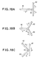
- Fig. 18A, 18B and 18C are schematic partial plan views, each illustrating connection of the nonlinear optical element of the present invention with optical fibers for achieving injection mode locking or photoamplifying.
- the nonlinear optical element 30 is connected to two or more optical fibers 82.
- Arrows a, b and c indicate the directions of propagation of an excitation beam, a control beam, and signal beam (light emission) after control, respectively.
- the arrangement of network comprising such nonlinear optical element (transparent microsphere) in two or three dimensions enables parallel processing of information.
- nonlinear optical element was fabricated in the same manner as above except that the transparent microsphere was prepared by using phosphate glass in place of silicate glass. Similar measurement to the above was conducted on this nonlinear optical element, which measurement confirmed that lasing in the band of 1054 nm took place.
- the nonlinear optical element serves also as a phase conjugate mirror.
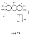
- Fig. 19 is a schematic cross sectional view showing a nonlinear optical element of this example, transmission of whispering gallery mode from microsphere to microsphere and enhancement of emission intensity will be explained.
- the transparent microspheres 34a, 34b and 34c were arranged and fixed onto the substrate 32 made of quartz in the same manner as in Example 1 so that the transparent microspheres 34a, 34b and 34c were arranged in a line with contacting one another to obtain a nonlinear optical element in which the nonlinear optical active region is present within the respective transparent microspheres 34a, 34b and 34c.
- the first transparent microsphere 34a was irradiated an excitation beam with a wavelength of 530 nm to establish whispering gallery modes with wavelengths in the region of 600 to 630 nm not only in the first microsphere 34a but also in the second microsphere 34b, which contacts the first one directly and in the third microsphere 34c, which contacts the first microsphere indirectly or via the second microsphere 34b.
- Irradiation of a control beam with a wavelength in the region of the wavelengths of laser emission through the optical fiber 64 to the third microsphere in the same manner as in Example 5 resulted in the enhancement of the intensity of light emission from the third microsphere 34c.
- Regular spherical, transparent microspheres made of polystyrene containing Nile Red and having particle diameters of 30 ⁇ m and 40 ⁇ m, respectively, were prepared in the same manner as in Example 1 and fixed onto a substrate made of glass using an adhesive (solid medium) in the same manner as in Example 1 so that the transparent microspheres were arranged with contacting one another to obtain a nonlinear optical element.
- Example 3 To the transparent microsphere with a particle diameter of 40 ⁇ m was selectively irradiated an excitation beam with a wavelength of 530 nm in the same manner as in Example 1. As a result, it was observed that a part of the whispering gallery modes to be established in the 40 ⁇ m-microsphere were transferred into the 30 ⁇ m-microsphere, resulting in simplification of the modes. The results show that it is possible to simplify whispering gallery modes using the nonlinear optical element having transparent microspheres with different particle diameters. Further, it was confirmed that in a state where whispering gallery modes were established in the respective transparent microspheres with different particle diameters, irradiation of a control beam to one microsphere in the same manner as in Example 3 enabled control of laser emission modes in another microsphere.
- irradiation of a control beam with a wavelength (610 nm) corresponding to that of the mode characteristic to one of the transparent microspheres decreased the intensity of light emission with a wavelength (510.5 nm) corresponding to that of the mode characteristic to the other of the transparent microspheres to 10 % or less of the intensity without irradiation of the control beam.
- the results show that connection of transparent microspheres enables coupling of light confinement modes.
- the nonlinear optical element having the transparent microspheres arranged and fixed unidimensionally, two-dimensionally or three-dimensionally can be utilized in highly directional light sources, short pulsed light sources, etc., based on the modes of a plurality of transparent microspheres and synchronized lasing, and also in optical integrated circuits for signal transmission based on collection or array of transparent microspheres.
- the results show connection of the transparent microspheres one to another enables diversification of light emission modes.
- an excitation beam was irradiated to the nonlinear optical element using a red semiconductor laser as the excitation beam source and selecting the wavelength of the excitation beam such that transparency of neodymium glass was 20 cm -1 or higher, and absorption intensity of Nd 3+ ion was 0.5 to 50 % of the absorption intensity at ⁇ max .
- the intensities of absorption spectra were measured using the apparatus for measuring nonlinear optical characteristics shown in Fig. 8. As a result, optical bistability depending on the intensity of the excitation beam was observed, which shows that the nonlinear optical element can function as an intrinsic optically bistable element.
Landscapes
- Physics & Mathematics (AREA)
- Nonlinear Science (AREA)
- General Physics & Mathematics (AREA)
- Optics & Photonics (AREA)
- Optical Modulation, Optical Deflection, Nonlinear Optics, Optical Demodulation, Optical Logic Elements (AREA)
- Lasers (AREA)
Claims (18)
- Nichtlinearoptisches Element (30) mit einem Substrat (32) und mindestens einer auf dem Substrat (32) befestigten transparenten Mikrokugel (35), dadurch gekennzeichnet, daß die transparenten Mikrokugeln (35) aus zwei Substanzen bestehen, nämlich aus einer nichtlinearoptischen aktiven Substanz und einem organischen Polymer, daß die transparente Mikrokugel (35) aus einem Kernpartikel (34) besteht, das aus einer der beiden Substanzen hergestellt ist, daß eine äußere schalenartige Schicht (33), welche auf dem Kernpartikel (34) ausgebildet ist, aus der anderen der beiden Substanzen hergestellt ist, und daß die nichtlinearoptische Substanz einen nichtlinearoptischen Koeffizienten χ3 von 10-13 esu oder größer aufweist.
- Nichtlinearoptisches Element nach Anspruch 1, wobei das nichtlinearoptisches Element (30) ferner ein festes Medium (36) aufweist, mittels welchem die mindestens eine transparente Mikrokugel auf dem Substrat befestigt ist.
- Nichtlinearoptisches Element nach Anspruch 1 oder 2, wobei die schalenartige Schicht (33) die Oberfläche des Kernpartikels (34) konzentrisch dazu überdeckt.
- Nichtlinearoptisches Element nach Anspruch 3, wobei die schalenartige Schicht (33) das nichtlinearoptische aktive Substanzsystem aufweist.
- Nichtlinearoptisches Element nach einem der Ansprüche 1 bis 4, wobei das optische Element (30) mehrere von den transparenten Mikrokugeln (34) in eindimensionaler Anordnung aufweist.
- Nichtlinearoptisches Element nach einem der Ansprüche 1 bis 4, wobei das optische Element (30) mehrere von den transparenten Mikrokugeln (34) in zweidimensionaler Anordnung aufweist.
- Nichtlinearoptisches Element nach einem der Ansprüche 1 bis 4, wobei das optische Element (30) mehrere von den transparenten Mikrokugeln (34) in dreidimensionaler Anordnung aufweist.
- Nichtlinearoptisches Element nach einem der Ansprüche 1 bis 7, wobei die transparente Mikrokugel (35) einen Partikeldurchmesser von 1 bis 200 µm aufweist.
- Nichtlinearoptisches System, dadurch gekennzeichnet, daß es aufweist:1) eine Anregungsstrahlquelle (56), und2) ein nichtlinearoptisches Element (30) nach einem der Ansprüche 1 bis 8.
- Nichtlinearoptisches System nach Anspruch 9, ferner mit:3) einer Steuerstrahlquelle (59), die optisch mit dem nichtlinearoptischen Element (30) verbunden ist.
- Verfahren zum Verstärken von Licht mit den Schritten:1) Bereitstellen einer Anregungsstrahlquelle (56) und eines nichtlinearoptischen Elementes (30) nach einem der Ansprüche 1 bis 8, das optisch mit der Anregungsstrahlquelle (56) verbunden ist;2) Aufstrahlen eines Anregungsstrahls aus der Anregungsstrahlquelle (56) auf das nichtlinearoptische Element (30) zum Anregen eines nichtlinearoptischen aktiven Mediums in der mindestens einen transparenten Mikrokugel (34); und3) Einleiten eines Signalstrahls in die mindestens eine transparente Mikrokugel (34) und wiederholtes Reflektieren des Strahls in der mindestens einen transparenten Mikrokugel (34), um den Signalstrahl zu verstärken.
- Verfahren zum Verstärken von Licht nach Anspruch 11, ferner mit dem Schritt:4) Aufstrahlen eines Steuerstrahls aus einer Steuerstrahlquelle (59) auf die mindestens eine transparente Mikrokugel (34), wobei der Steuerstrahl eine spezifizierte Wellenlänge in einem Wellenlängenbereich aufweist, der gleich dem des Signalstrahls ist, um dadurch die Lichtemissionsintensität des Signalstrahls in der mindestens einen transparenten Mikrokugel (34) zu erhöhen.
- Verfahren zum Steuern des Injektionsmodus mit den Schritten:1) Bereitstellen einer Anregungsstrahlquelle (56) und eines nichtlinearoptischen Elementes (30) nach einem der Ansprüche 1 bis 8, das optisch mit der Anregungsstrahlquelle (56) verbunden ist;2) Aufstrahlen eines Anregungsstrahls aus der Anregungsstrahlquelle (56) auf das nichtlinearoptische Element (30) zum Einleiten des Anregungsstrahls in die mindestens eine transparente Mikrokugel (34), um einen Strahl in der mindestens einen transparenten Mikrokugel (34) zu emittieren;3) wiederholtes Reflektieren des Strahls in der mindestens einen transparenten Mikrokugel (34) zum Bewirken einer Laseremission, um einen Laserstrahl zu emittieren; und4) Aufstrahlen eines Steuerstrahls aus einer Steuerstrahlquelle (59) auf die mindestens eine transparente Mikrokugel (34), wobei der Steuerstrahl eine spezifizierte Wellenlänge in einem Wellenlängenbereich aufweist, der entsprechend dem des Laserstrahls ist, um dadurch die Laseremissionsintensität der mindestens einen transparenten Mikrokugel (34) zu erhöhen, um den Injektionsmodus bei einer Ordnungszahl entsprechend der des Steuerstrahls zu steuern.
- Verfahren zum optischen Schalten mit den Schritten:1) Bereitstellen einer Anregungsstrahlquelle (56) und eines nichtlinearoptischen Elementes (30) nach einem der Ansprüche 1 bis 8, das optisch mit der Anregungsstrahlquelle (56) verbunden ist;2) Aufstrahlen eines Anregungsstrahls aus der Anregungsstrahlquelle (56) auf das nichtlinearoptische Element (30) zum Einleiten des Anregungsstrahls in die mindestens eine transparente Mikrokugel (34), um einen Strahl in der mindestens einen transparenten Mikrokugel (34) zu emittieren;3) wiederholtes Reflektieren des Strahls in der mindestens einen transparenten Mikrokugel zum Bewirken einer Laseremission, um einen Laserstrahl zu emittieren;4) Aufstrahlen eines Steuerstrahls aus einer Steuerstrahlquelle (59) auf die mindestens eine transparente Mikrokugel (34), wobei der Steuerstrahl eine spezifizierte Wellenlänge in einem Wellenlängenbereich aufweist, der entsprechend dem des Laserstrahls ist, um dadurch die Laseremissionsintensität der mindestens einen transparenten Mikrokugel (34) zu erhöhen, um den Injektionsmodus bei einer Ordnungszahl entsprechend der des Steuerstrahls zu steuern; und5) Ein- und Ausschalten des Steuerstrahls, um optisches Schalten zu realisieren.
- Verfahren zum Koppeln von Flüstermodi mit den Schritten:1) Bereitstellen einer Anregungsstrahlquelle (56) und eines nichtlinearoptischen Elementes (30) nach einem der Ansprüche 5 bis 7, das optisch mit der Anregungsstrahlquelle (56) verbunden ist;2) Aufstrahlen eines Anregungsstrahls aus der Anregungsstrahlquelle (56) auf das nichtlinearoptische Element (30) zum Einleiten des Anregungsstrahls in die mehreren transparenten Mikrokugeln (34), um mindestens einen Strahl zu erzeugen; und3) wiederholtes Reflektieren des mindestens einen Strahls in den mehreren transparenten Mikrokugeln (34).
- Verfahren zum Koppeln von Flüstermodi nach Anspruch 15, ferner mit dem Schritt:4) Aufstrahlen eines Steuerstrahls auf mindestens eine von den mehreren transparenten Mikrokugeln (34) mit einer spezifizierten Wellenlänge in einem Wellenlängenbereich entsprechend der, die für die eine von den mehreren transparenten Mikrokugeln (34) charakteristisch ist, um dadurch die Flüstermodi zu steuern.
- Verfahren zum Koppeln von Flüstermodi nach Anspruch 15 oder 16, wobei mindestens zwei von den mehreren transparenten Mikrokugeln (34) jeweils unterschiedliche Durchmesser aufweisen.
- Anwenden eines nichtlinearoptischen Elementes nach einem der Ansprüche 1 bis 8 bei der Steuerung nichtlinearoptischer Eigenschaften einer optischen Vorrichtung.
Applications Claiming Priority (2)
| Application Number | Priority Date | Filing Date | Title |
|---|---|---|---|
| JP4224191 | 1991-02-15 | ||
| JP42241/91 | 1991-02-15 |
Publications (3)
| Publication Number | Publication Date |
|---|---|
| EP0499272A2 EP0499272A2 (de) | 1992-08-19 |
| EP0499272A3 EP0499272A3 (en) | 1993-12-01 |
| EP0499272B1 true EP0499272B1 (de) | 1998-10-21 |
Family
ID=12630534
Family Applications (1)
| Application Number | Title | Priority Date | Filing Date |
|---|---|---|---|
| EP92102511A Expired - Lifetime EP0499272B1 (de) | 1991-02-15 | 1992-02-14 | Nichtlinearoptisches Element und seine Verwendung |
Country Status (3)
| Country | Link |
|---|---|
| US (1) | US5231533A (de) |
| EP (1) | EP0499272B1 (de) |
| DE (1) | DE69227332T2 (de) |
Cited By (2)
| Publication number | Priority date | Publication date | Assignee | Title |
|---|---|---|---|---|
| US6661942B1 (en) | 1998-07-20 | 2003-12-09 | Trans Photonics, Llc | Multi-functional optical switch (optical wavelength division multiplexer/demultiplexer, add-drop multiplexer and inter-connect device) and its methods of manufacture |
| US7205347B2 (en) | 2000-10-19 | 2007-04-17 | Trans Photonics, Llc. | Substituted-polyaryl chromophoric compounds |
Families Citing this family (37)
| Publication number | Priority date | Publication date | Assignee | Title |
|---|---|---|---|---|
| US5731075A (en) * | 1990-11-21 | 1998-03-24 | Mitsuboshi Belting Ltd. | Colorant for a transparent substrate and method of making the colorant |
| EP0598472B1 (de) * | 1992-08-20 | 1997-06-18 | Mitsuboshi Belting Ltd. | Glasartiger Werkstoff mit ultrafeinen dispergierten Teilchen und Verfahren zu seiner Herstellung |
| US6614161B1 (en) * | 1993-07-20 | 2003-09-02 | University Of Georgia Research Foundation, Inc. | Resonant microcavity display |
| US5663972A (en) * | 1995-04-03 | 1997-09-02 | The Regents Of The University Of California | Ultrafast pulsed laser utilizing broad bandwidth laser glass |
| GB2302442B (en) * | 1995-06-02 | 1999-09-22 | Central Glass Co Ltd | Upconversion laser material |
| US7622294B2 (en) * | 1997-03-14 | 2009-11-24 | Trustees Of Tufts College | Methods for detecting target analytes and enzymatic reactions |
| US20030027126A1 (en) | 1997-03-14 | 2003-02-06 | Walt David R. | Methods for detecting target analytes and enzymatic reactions |
| US6429023B1 (en) | 1998-07-20 | 2002-08-06 | Shayda Technologies, Inc. | Biosensors with polymeric optical waveguides |
| US6839368B2 (en) * | 2000-03-17 | 2005-01-04 | Mrinal Thakur | Dipolar organic materials producing highly efficient laser-like emission |
| CN1172411C (zh) * | 2001-04-18 | 2004-10-20 | 中国科学院理化技术研究所 | 一种非线性光学晶体激光变频耦合器 |
| CN1854778A (zh) | 2001-06-20 | 2006-11-01 | 阿尔利克斯公司 | 光开关和光路由器以及光滤波器 |
| EP1793249A3 (de) * | 2001-06-20 | 2007-08-29 | Arryx, Inc. | Optische schalter und router und optische filter |
| US7283707B1 (en) | 2001-07-25 | 2007-10-16 | Oewaves, Inc. | Evanescently coupling light between waveguides and whispering-gallery mode optical resonators |
| US6853479B1 (en) | 2001-08-30 | 2005-02-08 | Oewaves, Inc. | Apparatus and method for coupling light between an optical resonator and a semiconductor chip with a minimum number of components and alignment steps |
| US7491491B2 (en) * | 2002-03-12 | 2009-02-17 | Polytechnic Institute Of New York University | Detecting and/or measuring a substance based on a resonance shift of photons orbiting within a microsphere |
| US6879752B1 (en) | 2002-04-03 | 2005-04-12 | Oewaves, Inc. | Film spacer for setting the gap between an optical coupler and a whispering-gallery mode optical resonator |
| US6943934B1 (en) * | 2002-05-28 | 2005-09-13 | California Institute Of Technology | Nonlinear optical whispering gallery mode resonators |
| US20040184711A1 (en) * | 2002-06-20 | 2004-09-23 | Kenneth Bradley | Optical switches and routers and optical filters |
| US20040137478A1 (en) * | 2002-10-22 | 2004-07-15 | Stephen Arnold | Enhancing the sensitivity of a microsphere sensor |
| US20040196465A1 (en) * | 2002-12-12 | 2004-10-07 | Stephen Arnold | Using a change in one or more properties of light in one or more microspheres for sensing chemicals such as explosives and poison gases |
| US20040238744A1 (en) * | 2003-01-15 | 2004-12-02 | Stephen Arnold | Perturbation approach to resonance shift of whispering gallery modes in a dielectric microsphere as a probe of a surrounding medium |
| WO2005124414A1 (fr) * | 2004-06-14 | 2005-12-29 | France Telecom | Concentrateur amplificateur d'onde electromagnetique optique |
| US7846391B2 (en) * | 2006-05-22 | 2010-12-07 | Lumencor, Inc. | Bioanalytical instrumentation using a light source subsystem |
| WO2008108824A2 (en) * | 2006-10-10 | 2008-09-12 | The Trustees Of The University Of Pennsylvania | Lumped plasmonic diode and lumped plasmonic rectifier |
| US7709811B2 (en) * | 2007-07-03 | 2010-05-04 | Conner Arlie R | Light emitting diode illumination system |
| US8098375B2 (en) * | 2007-08-06 | 2012-01-17 | Lumencor, Inc. | Light emitting diode illumination system |
| JP5205125B2 (ja) * | 2008-05-28 | 2013-06-05 | スタンレー電気株式会社 | 光増幅器及びその設計方法 |
| US8242462B2 (en) * | 2009-01-23 | 2012-08-14 | Lumencor, Inc. | Lighting design of high quality biomedical devices |
| US8642111B2 (en) * | 2009-05-19 | 2014-02-04 | Polytechnic Institute Of New York University | Functionalizing a sensing ribbon on a whispering gallery mode microresonator using light force to fabricate a whispering gallery mode sensor |
| US8466436B2 (en) | 2011-01-14 | 2013-06-18 | Lumencor, Inc. | System and method for metered dosage illumination in a bioanalysis or other system |
| US8389957B2 (en) | 2011-01-14 | 2013-03-05 | Lumencor, Inc. | System and method for metered dosage illumination in a bioanalysis or other system |
| US9642515B2 (en) | 2012-01-20 | 2017-05-09 | Lumencor, Inc. | Solid state continuous white light source |
| US9217561B2 (en) | 2012-06-15 | 2015-12-22 | Lumencor, Inc. | Solid state light source for photocuring |
| KR101411428B1 (ko) * | 2012-07-12 | 2014-06-24 | 한국과학기술원 | 집광식 휴대용 형광 검출 시스템 |
| US11804694B2 (en) * | 2019-03-27 | 2023-10-31 | Samsung Electronics Co., Ltd. | Laser device and method of transforming laser spectrum |
| CN111240096B (zh) * | 2020-03-13 | 2021-07-06 | Tcl华星光电技术有限公司 | 背光模组及具有该背光模组的显示装置 |
| US11791902B2 (en) * | 2020-12-16 | 2023-10-17 | Mellanox Technologies, Ltd. | Heterogeneous integration of frequency comb generators for high-speed transceivers |
Family Cites Families (6)
| Publication number | Priority date | Publication date | Assignee | Title |
|---|---|---|---|---|
| US4597638A (en) * | 1983-02-28 | 1986-07-01 | At&T Bell Laboratories | Nonlinear optical apparatus |
| US4986635A (en) * | 1986-10-31 | 1991-01-22 | The United States Of America As Represented By The Secretary Of The Air Froce | High efficiency nonlinear Kerr effect filter |
| US4829537A (en) * | 1986-12-01 | 1989-05-09 | Spectra-Physics, Inc. | Solid state lasers with spherical resonators |
| US5002369A (en) * | 1988-01-11 | 1991-03-26 | Canon Kabushiki Kaisha | Nonlinear optical element having electrodes on two side surfaces of nonlinear medium through insulating layers |
| US4803688A (en) * | 1988-03-28 | 1989-02-07 | Lawandy Nabil M | Ordered colloidal suspension optical devices |
| US5023139A (en) * | 1989-04-04 | 1991-06-11 | Research Corporation Technologies, Inc. | Nonlinear optical materials |
-
1992
- 1992-02-13 US US07/834,799 patent/US5231533A/en not_active Expired - Lifetime
- 1992-02-14 EP EP92102511A patent/EP0499272B1/de not_active Expired - Lifetime
- 1992-02-14 DE DE69227332T patent/DE69227332T2/de not_active Expired - Lifetime
Cited By (2)
| Publication number | Priority date | Publication date | Assignee | Title |
|---|---|---|---|---|
| US6661942B1 (en) | 1998-07-20 | 2003-12-09 | Trans Photonics, Llc | Multi-functional optical switch (optical wavelength division multiplexer/demultiplexer, add-drop multiplexer and inter-connect device) and its methods of manufacture |
| US7205347B2 (en) | 2000-10-19 | 2007-04-17 | Trans Photonics, Llc. | Substituted-polyaryl chromophoric compounds |
Also Published As
| Publication number | Publication date |
|---|---|
| US5231533A (en) | 1993-07-27 |
| EP0499272A3 (en) | 1993-12-01 |
| DE69227332T2 (de) | 1999-03-25 |
| EP0499272A2 (de) | 1992-08-19 |
| DE69227332D1 (de) | 1998-11-26 |
Similar Documents
| Publication | Publication Date | Title |
|---|---|---|
| EP0499272B1 (de) | Nichtlinearoptisches Element und seine Verwendung | |
| US5481630A (en) | Optically encoded phase matched second harmonic generation, self frequency doubling laser material, and optical switch using semiconductor microcrystallite doped glasses | |
| Mukherjee | Two‐photon pumped upconverted lasing in dye doped polymer waveguides | |
| Sasaki et al. | Ultrafast wide range all-optical switch using complex refractive-index changes in a composite film of silver and polymer containing photochromic dye | |
| Jewell et al. | 3‐pJ, 82‐MHz optical logic gates in a room‐temperature GaAs‐AlGaAs multiple‐quantum‐well étalon | |
| JPH0690334B2 (ja) | 放射源と導波路を含むシステム | |
| US7466727B2 (en) | Passive Q-switch laser | |
| Denning | New optics—new materialsBasis of a presentation given at Materials Discussion No. 3, 26–29 September, 2000, University of Cambridge, UK. | |
| Patela et al. | Nonlinear optical properties of thin‐film waveguides deposited onto semiconductor‐doped glasses | |
| JP3305741B2 (ja) | 非線形光学素子 | |
| JP3504076B2 (ja) | 光制御方法および光制御装置 | |
| US5487080A (en) | Principle and applications of multiphoton pumped upconverted lasers | |
| US7173949B2 (en) | Laser effects and laser devices | |
| Horinouchi et al. | Fabrication and characterization of rare-earth metal-chelate-doped plastic film and fiber materials: Eu (3+)-chelate-doped PMMA | |
| GB2289159A (en) | Frequency doubling laser material | |
| Khoo et al. | Nonlinear Optical Effects in Nematic Liquid-Crystal Films in the 1.55 µm Spectral Region | |
| Rossi et al. | Degenerate four‐wave mixing in rhodamine doped epoxy waveguides | |
| Nagamura et al. | All-optical parallel switching by the use of guided-wave geometry composed of a thin silver film and a polymer thin film containing organic dye | |
| EP0269730B1 (de) | Optische vorrichtung | |
| Belousov et al. | Some regularities of nonlinear-optical limitation of laser radiation by fullerene-containing materials | |
| Sharma | Polymeric thin films for integrated optics. | |
| Beeson et al. | All-optical switching by organic nonlinearly absorbing molecules | |
| Xie et al. | Reflective optical bistability in a GaAs/GaAlAs multiple quantum well waveguide with a grating | |
| Jewell | Fabrication, Investigation and Optimization of Gallium-arsenide Optical Bistable Devices and Logic Gates | |
| Darwish et al. | Transient multiple diffraction rings induced by Ar+ laser from poly (methyl methacrylate)(PMMA) polymer doped with organic dyes |
Legal Events
| Date | Code | Title | Description |
|---|---|---|---|
| PUAI | Public reference made under article 153(3) epc to a published international application that has entered the european phase |
Free format text: ORIGINAL CODE: 0009012 |
|
| AK | Designated contracting states |
Kind code of ref document: A2 Designated state(s): DE FR GB |
|
| RIN1 | Information on inventor provided before grant (corrected) |
Inventor name: GONOKAMI, MAKOTO Inventor name: HANAMURA, EIICHI Inventor name: TAKEDA, KENJI Inventor name: TOKURA, YOSHINORI |
|
| PUAL | Search report despatched |
Free format text: ORIGINAL CODE: 0009013 |
|
| AK | Designated contracting states |
Kind code of ref document: A3 Designated state(s): DE FR GB |
|
| 17P | Request for examination filed |
Effective date: 19940311 |
|
| 17Q | First examination report despatched |
Effective date: 19951027 |
|
| GRAG | Despatch of communication of intention to grant |
Free format text: ORIGINAL CODE: EPIDOS AGRA |
|
| GRAG | Despatch of communication of intention to grant |
Free format text: ORIGINAL CODE: EPIDOS AGRA |
|
| GRAG | Despatch of communication of intention to grant |
Free format text: ORIGINAL CODE: EPIDOS AGRA |
|
| GRAH | Despatch of communication of intention to grant a patent |
Free format text: ORIGINAL CODE: EPIDOS IGRA |
|
| GRAH | Despatch of communication of intention to grant a patent |
Free format text: ORIGINAL CODE: EPIDOS IGRA |
|
| GRAA | (expected) grant |
Free format text: ORIGINAL CODE: 0009210 |
|
| AK | Designated contracting states |
Kind code of ref document: B1 Designated state(s): DE FR GB |
|
| REF | Corresponds to: |
Ref document number: 69227332 Country of ref document: DE Date of ref document: 19981126 |
|
| PLBE | No opposition filed within time limit |
Free format text: ORIGINAL CODE: 0009261 |
|
| STAA | Information on the status of an ep patent application or granted ep patent |
Free format text: STATUS: NO OPPOSITION FILED WITHIN TIME LIMIT |
|
| 26N | No opposition filed | ||
| REG | Reference to a national code |
Ref country code: GB Ref legal event code: IF02 |
|
| PGFP | Annual fee paid to national office [announced via postgrant information from national office to epo] |
Ref country code: FR Payment date: 20110302 Year of fee payment: 20 Ref country code: DE Payment date: 20110218 Year of fee payment: 20 |
|
| PGFP | Annual fee paid to national office [announced via postgrant information from national office to epo] |
Ref country code: GB Payment date: 20110217 Year of fee payment: 20 |
|
| REG | Reference to a national code |
Ref country code: DE Ref legal event code: R071 Ref document number: 69227332 Country of ref document: DE |
|
| REG | Reference to a national code |
Ref country code: DE Ref legal event code: R071 Ref document number: 69227332 Country of ref document: DE |
|
| REG | Reference to a national code |
Ref country code: GB Ref legal event code: PE20 Expiry date: 20120213 |
|
| PG25 | Lapsed in a contracting state [announced via postgrant information from national office to epo] |
Ref country code: DE Free format text: LAPSE BECAUSE OF EXPIRATION OF PROTECTION Effective date: 20120215 |
|
| PG25 | Lapsed in a contracting state [announced via postgrant information from national office to epo] |
Ref country code: GB Free format text: LAPSE BECAUSE OF EXPIRATION OF PROTECTION Effective date: 20120213 |