EP0499135A1 - A toothed, flexible transmission cable, a method for its manufacture, and a transmission mechanism including the cable - Google Patents
A toothed, flexible transmission cable, a method for its manufacture, and a transmission mechanism including the cable Download PDFInfo
- Publication number
- EP0499135A1 EP0499135A1 EP92101943A EP92101943A EP0499135A1 EP 0499135 A1 EP0499135 A1 EP 0499135A1 EP 92101943 A EP92101943 A EP 92101943A EP 92101943 A EP92101943 A EP 92101943A EP 0499135 A1 EP0499135 A1 EP 0499135A1
- Authority
- EP
- European Patent Office
- Prior art keywords
- teeth
- cable
- groove
- semi
- finished product
- Prior art date
- Legal status (The legal status is an assumption and is not a legal conclusion. Google has not performed a legal analysis and makes no representation as to the accuracy of the status listed.)
- Granted
Links
- 238000000034 method Methods 0.000 title claims abstract description 15
- 230000005540 biological transmission Effects 0.000 title claims description 11
- 238000004519 manufacturing process Methods 0.000 title claims description 5
- 230000007246 mechanism Effects 0.000 title description 4
- 239000011265 semifinished product Substances 0.000 claims abstract description 22
- 239000012815 thermoplastic material Substances 0.000 claims abstract description 16
- 230000003014 reinforcing effect Effects 0.000 claims abstract description 4
- 230000009347 mechanical transmission Effects 0.000 claims description 5
- 230000002093 peripheral effect Effects 0.000 claims description 5
- 238000001125 extrusion Methods 0.000 claims description 4
- 235000012438 extruded product Nutrition 0.000 claims 1
- 229930182556 Polyacetal Natural products 0.000 description 2
- 229910000831 Steel Inorganic materials 0.000 description 2
- 230000008901 benefit Effects 0.000 description 2
- 229920006324 polyoxymethylene Polymers 0.000 description 2
- 239000011347 resin Substances 0.000 description 2
- 229920005989 resin Polymers 0.000 description 2
- 230000002441 reversible effect Effects 0.000 description 2
- 239000010959 steel Substances 0.000 description 2
- 239000004809 Teflon Substances 0.000 description 1
- 229920006362 Teflon® Polymers 0.000 description 1
- 230000004075 alteration Effects 0.000 description 1
- 230000008859 change Effects 0.000 description 1
- 230000007423 decrease Effects 0.000 description 1
- 230000006872 improvement Effects 0.000 description 1
- 239000000463 material Substances 0.000 description 1
- 238000002844 melting Methods 0.000 description 1
- 230000008018 melting Effects 0.000 description 1
- 239000002184 metal Substances 0.000 description 1
- -1 polytetrafluoroethylene Polymers 0.000 description 1
- 229920001343 polytetrafluoroethylene Polymers 0.000 description 1
- 239000004810 polytetrafluoroethylene Substances 0.000 description 1
- 229920002994 synthetic fiber Polymers 0.000 description 1
Images


Classifications
-
- F—MECHANICAL ENGINEERING; LIGHTING; HEATING; WEAPONS; BLASTING
- F16—ENGINEERING ELEMENTS AND UNITS; GENERAL MEASURES FOR PRODUCING AND MAINTAINING EFFECTIVE FUNCTIONING OF MACHINES OR INSTALLATIONS; THERMAL INSULATION IN GENERAL
- F16H—GEARING
- F16H55/00—Elements with teeth or friction surfaces for conveying motion; Worms, pulleys or sheaves for gearing mechanisms
- F16H55/02—Toothed members; Worms
- F16H55/26—Racks
-
- F—MECHANICAL ENGINEERING; LIGHTING; HEATING; WEAPONS; BLASTING
- F16—ENGINEERING ELEMENTS AND UNITS; GENERAL MEASURES FOR PRODUCING AND MAINTAINING EFFECTIVE FUNCTIONING OF MACHINES OR INSTALLATIONS; THERMAL INSULATION IN GENERAL
- F16C—SHAFTS; FLEXIBLE SHAFTS; ELEMENTS OR CRANKSHAFT MECHANISMS; ROTARY BODIES OTHER THAN GEARING ELEMENTS; BEARINGS
- F16C1/00—Flexible shafts; Mechanical means for transmitting movement in a flexible sheathing
- F16C1/10—Means for transmitting linear movement in a flexible sheathing, e.g. "Bowden-mechanisms"
- F16C1/20—Construction of flexible members moved to and fro in the sheathing
Definitions
- the present invention relates to flexible cables for mechanical traction and thrust transmissions and concerns in particular a cable of this type which is constituted by an elongate body of thermoplastic material, with or without a central reinforcing core, and formed with an external series of projections and recesses constituting a set of teeth.
- cables of this type are described in the documents DE-A-2 264 072, IT-B-1 130 529, US-A-4 402 160, EP-A-0 199 417 and US-A-4 767 386.
- Canonical shapes means, in particular, shapes with toothed profiles such that they can establish continuous surface contact with a conjugate set of teeth, particularly an involute set of teeth with straight, helical or herring-bone teeth.
- toothed cables of the type described in the documents IT-B-1 130 529 and US-A-4 402 160 the teeth of which have the profiles normally used for racks.
- the sets of teeth mesh with a conjugate gear only in a plane which contains the axis of the cable and is perpendicular to the axis of the gear, whilst in all the other regions on either side of this plane there is no certain contact between the teeth.
- An object of the present invention is to provide a flexible cable of the type in question which enables perfect meshing with a conjugate gear without localised pressures and without slippage.
- this object is achieved by means of a flexible cable, characterised in that the body of thermoplastic material is generally cylindrical and has at least one rack in the form of a set of teeth stamped in its surface and having teeth with cross-sections which are uniform along cords of the cylinder.
- a rack means a cylindrical gear with an infinite pitch-circle radius.
- the definitions given in the description and in the claims relate to a flexible cable in the rectilinear rest condition.
- a cable according to the invention can be applied to a transmission mechanism with a single gear or with several gears with parallel axes.
- a cable with a single rack is sufficient. If the mechanism includes gears with parallel axes situated on either side of the cable, the cable will have two diametrally-opposed racks.
- a flexible cable according to the invention may be produced, to advantage, by a method characterised in that a generally cylindrical semi-finished product of thermoplastic material, with or without a central core, is extruded and in that the semi-finished product is then formed continuously by hot deformation by means of at least one revolving tooth-forming member with a peripheral, toothed forming profile which stamps the set of teeth in the semi-finished product along a generatrix thereof, so as to form therein a rack having teeth with cross-sections which are uniform along chords of the cylinder, that is, a canonical set of teeth.
- the invention also relates to mechanical transmission devices including one or more toothed cables according to the invention.
- a cable according to the invention includes a generally cylindrical, elongate body 10 of indeterminate length.
- the body 10 is made of a mechanically strong and wear-resistant thermoplastic material such as a polyacetal resin.
- the body 10 may have a diameter of 6 mm and the wire 12 may have a diameter of 1.5 mm with 49 strands.
- a rack 14 is stamped in the surface of the body 10.
- the teeth 16 of the rack 14 have cross-sections which are uniform along chords of the cylinder constituted by the body 10.
- the teeth 16 are straight and have straight, flat faces with canonical profiles.
- the teeth 16 are shaped like segments of a circle. This means that the height of the cross-section of each tooth decreases from its centre towards its side edges.
- the canonical profiles of the teeth do not change, however, and they can thus mesh correctly with a conjugate set of teeth of a corresponding gear with an involute set of teeth.
- the teeth 16 may have a pitch of 2.5 mm and maximum heights of 1.5 mm along the diameter of the cylinder.
- a longitudinal groove 18 is stamped in the body 10 in a position diametrally opposite the rack 14 and, as will be seen from the following, acts as an alignment guide. The positioning of the groove 18 diametrally opposite the rack 14 is preferred, but not necessary.
- the depth of the groove 18 is approximately equal to the heights of the teeth 16.
- a cable such as that shown in Figures 1 to 3 is suitable for use in a mechanical transmission having only one gear, or several gears all with parallel axes and situated on the same side of the cable, so that they can all mesh with the single rack 14.
- the body of the cable of Figure 4 which is also of thermoplastic material, is indicated 10a and is generally cylindrical.
- the body 10a may also incorporate a central core 12 of thin metal wire.
- the body 10a has two diametrally opposed sets of teeth 14a with teeth 16a exactly like the teeth 16 of the body 10 of Figures 1 to 3.
- two diametrally opposed guide grooves 18a are stamped in the body 10a, between the two sets of teeth 16a.
- the median planes of the sets of teeth 14a and of the grooves 18a are preferably at 90 o to each other.
- a cable such as that of Figure 4 could include only one groove 18a.
- an extrusion head indicated 20, includes a peripheral body 22 and a central core 24.
- thermoplastic material which is extruded through the duct 26 to form the body 10 of the cable is indicated 30.
- the core 24 of the head 20 has a longitudinal hole 31, through which the wire 12 for forming the core of the cable is fed.
- the orifice 28 in the die has an internal tooth or projection 32 which can be seen better in Figures 6 and 7 and which has a profile corresponding to that of the groove 18 of Figures 1 to 3.
- thermoplastic material 30 is extruded through the orifice 28 to form a semi-finished product 34 which, as it is formed, gradually incorporates the wire 12.
- the semi-finished product 34 is generally smooth and cylindrical.
- the semi-finished product 34 is set but, because of the extrusion temperature, is quite soft.
- the temperature at the output of the orifice 28 is preferably between 150 o and 160 o C.
- rollers 36 and 38 Immediately downstream of the orifice 28 is a pair of rollers 36 and 38 of which at least the roller 36 is motor-driven.
- the senses of rotation of the rollers 36 and 38 are indicated by the arrows R1 and R2 in Figure 5.
- the roller 36 constitutes a revolving tooth-forming member. As shown in Figures 5 and 8, it has a groove 40 of substantially semicircular cross-section which surrounds half of the semi-finished product 34.
- the base of the groove 40 has a set of teeth, or a peripheral, toothed profile 42 for forming the set of teeth, again indicated 14, to be produced on the cable.
- the tooth-forming roller 36 stamps the set of teeth 14 in the semi-finished product 34, which is still soft, as it is gradually extruded.
- the gear-forming roller 36 is rotated at a speed such that the tangential velocity of the set of teeth 42 along its pitch line in the working region is equal to the speed at which the semi-finished product 34 is extruded.
- the roller 38 is a counter-roller which reacts against the tooth-forming roller 36. As shown in Figures 5 and 8, the roller 38 also has a groove 44 of substantially semicircular cross-section which surrounds and houses the other half of the semi-finished product 34. In the base of the groove 44 is an annular rib 46 which exactly engages the longitudinal groove 18 already formed in the semi-finished product 34 and helps to ensure the correct shape of the groove 18 whilst the thermoplastic material is still soft.
- the tooth or projection 32 in the orifice 28 could be omitted and the roller 38 could act as a groove-forming member and stamp the continuous groove 18 in the semi-finished product 34 by means of its rib 46.
- a system like that of Figure 5 would include a pair of revolving gear-forming members, such as that indicated 36, which are diametrally opposed relative to the semi-finished product 34 and which contrarotate in synchronism in order to stamp the two sets of teeth 14a.
- the grooves 18a could be formed by a pair of teeth or projections like that indicated 32 in an extrusion orifice like that indicated 28, or by a pair of groove-forming members like that indicated 38, in a "cross-like" arrangement with the two groove-forming members like that indicated 36.
- the invention also provides for the use of revolving gear-forming members and/or revolving groove-forming members in the form of continuous belts which are toothed or ribbed, respectively.
- the revolving members such as those indicated 36 and 38 may be of steel but the use of members whose working surfaces, such as those of the set of teeth 42 and of the rib 46, are of a synthetic material which is resistant to high temperatures, is also envisaged.
- a preferred material is polytetrafluoroethylene, known by the trade name "Teflon", which has a melting point of between 270 o C and 305 o C.
- the transmission device is similar to that described and shown in co-pending European Patent Application No. 91121520.0.
- Figure 9 shows a motor-vehicle door 48 including a window 50 which can be lowered.
- the front and rear edges of the window 50 are guided in respective opposed parallel channels, both indicated 52.
- a reversible drive unit, generally indicated 54, is mounted in the lower region of the door 48 in a position intermediate the channels 52. Certain details of the unit 54 will be described with reference to Figure 10 and 11.
- a transmission member 56 which moves the window 50 up and down extends from the drive unit 54 towards each of the channels 52.
- the drive unit 54 includes a body 58 on which a reversible electric motor 60 is mounted.
- a gear 62 rotatable in the body 58, has a set of teeth 64 meshed with a worm screw 65 which is rotated by the motor 60.
- the gear 62 also includes another set of teeth 66 which will be mentioned further below.
- Each transmission member 56 includes a sheath which is flexible or can be shaped and in which a toothed, flexible cable 68, such as that of Figures 1 to 3, is slidable.
- Outlet tubes in which the excess portions of the toothed cables 68 are slidable, are indicated 70.
- the sets of teeth of the toothed cables 68 are meshed with diametrally-opposed regions of the set of teeth 66 of the gear 62. As will be understood, the rotation of the double gear 62 moves the two toothed cables 68 in synchronism in opposite directions.
- each of the cables 68 is oriented about its own axis so that its set of teeth 14 is correctly meshed with the set of teeth 66, the body 58 has corresponding guide blocks 72 in the meshing regions.
- each block 72 has a partially cylindrical cavity 74 which surrounds the respective portion of the cable 68 in the region in which its set of teeth 14 is meshed with the set of teeth 66 of the gear 62 so that it serves as a counterthrust member and houses the cable 68.
- the cavity 74 has a projection, rib or tooth 76 which is engaged like a spline in the longitudinal groove 18 to ensure the correct orientation of the set of teeth 14 relative to the teeth 66.
Landscapes
- Engineering & Computer Science (AREA)
- General Engineering & Computer Science (AREA)
- Mechanical Engineering (AREA)
- Extrusion Moulding Of Plastics Or The Like (AREA)
- Flexible Shafts (AREA)
- Gears, Cams (AREA)
Abstract
Description
- The present invention relates to flexible cables for mechanical traction and thrust transmissions and concerns in particular a cable of this type which is constituted by an elongate body of thermoplastic material, with or without a central reinforcing core, and formed with an external series of projections and recesses constituting a set of teeth.
- The prior art abounds with transmission cables of this type, in which the sets of teeth are constituted by a series of annular projections and corresponding annular recesses, or by continuous helical projections and corresponding continuous helical recesses.
- Examples of cables of this type are described in the documents DE-A-2 264 072, IT-B-1 130 529, US-A-4 402 160, EP-A-0 199 417 and US-A-4 767 386.
- Most of the cables according to these documents do not have canonical shapes.
- Canonical shapes means, in particular, shapes with toothed profiles such that they can establish continuous surface contact with a conjugate set of teeth, particularly an involute set of teeth with straight, helical or herring-bone teeth.
- It is not possible, in practice, to form pairs of gears with precisely conjugate sets of teeth with cables whose sets of teeth are not canonical in shape; the contacts between the teeth of the cable and those of the gear meshed therewith will always be limited so that there are undesirable concentrations of pressure or similarly undesirable slippages.
- A certain improvement of the situation can be achieved with toothed cables of the type described in the documents IT-B-1 130 529 and US-A-4 402 160, the teeth of which have the profiles normally used for racks. In this case also, however, the sets of teeth mesh with a conjugate gear only in a plane which contains the axis of the cable and is perpendicular to the axis of the gear, whilst in all the other regions on either side of this plane there is no certain contact between the teeth.
- An object of the present invention is to provide a flexible cable of the type in question which enables perfect meshing with a conjugate gear without localised pressures and without slippage.
- According to the invention, this object is achieved by means of a flexible cable, characterised in that the body of thermoplastic material is generally cylindrical and has at least one rack in the form of a set of teeth stamped in its surface and having teeth with cross-sections which are uniform along cords of the cylinder.
- Throughout the present description and in the claims, a rack means a cylindrical gear with an infinite pitch-circle radius. Moreover, the definitions given in the description and in the claims relate to a flexible cable in the rectilinear rest condition.
- By virtue of this concept, it is possible to produce a cable with a canonical set of teeth which are adapted to mesh perfectly with a gear which also has a canonical set of teeth, particularly with involute profiles.
- A cable according to the invention can be applied to a transmission mechanism with a single gear or with several gears with parallel axes.
- In the case of a mechanism with a single gear or several gears on the same side of the cable, a cable with a single rack is sufficient. If the mechanism includes gears with parallel axes situated on either side of the cable, the cable will have two diametrally-opposed racks.
- A flexible cable according to the invention may be produced, to advantage, by a method characterised in that a generally cylindrical semi-finished product of thermoplastic material, with or without a central core, is extruded and in that the semi-finished product is then formed continuously by hot deformation by means of at least one revolving tooth-forming member with a peripheral, toothed forming profile which stamps the set of teeth in the semi-finished product along a generatrix thereof, so as to form therein a rack having teeth with cross-sections which are uniform along chords of the cylinder, that is, a canonical set of teeth.
- The invention also relates to mechanical transmission devices including one or more toothed cables according to the invention.
- Further features and advantages of the invention will become clear from a reading of the detailed description which follows with reference to the appended drawings, given by way of non-limiting example, in which:
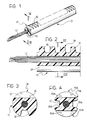
- Figure 1 is a perspective view of a portion of cable according to one embodiment of the invention,
- Figure 2 is a longitudinal section taken in the plane indicated II-II in Figure 1, on an enlarged scale,
- Figure 3 is a transverse section thereof taken in the plane indicated III-III in Figure 2,
- Figure 4 is a transverse section similar to that of Figure 3, showing an another embodiment of the cable according to the invention,
- Figure 5 is a partially-sectioned, schematic view showing a device for manufacturing a cable such as that of Figure 1,
- Figure 6 shows the detail indicated VI in Figure 5, on an enlarged scale,
- Figure 7 is a transverse section taken in the plane indicated VII-VII in Figure 5,
- Figure 8 is partially a front view and partially a transverse section taken, as indicated, in the plane VIII-VIII in Figure 5,
- Figure 9 is a schematic, elevational view of a motor-vehicle door with a window-winder device constituting an example of a mechanical transmission device incorporating cables according to the invention,
- Figure 10 shows, mostly in section and on an enlarged scale, a drive unit of the device, indicated X in Figure 9, and
- Figure 11 is a partial transverse section taken in the plane indicated XI-XI in Figure 10, on an even larger scale.
- With reference to Figures 1 to 3, a cable according to the invention includes a generally cylindrical,
elongate body 10 of indeterminate length. Thebody 10 is made of a mechanically strong and wear-resistant thermoplastic material such as a polyacetal resin. - A central reinforcing
core 12, constituted, for example, by a thin steel wire, is preferably incorporated in thebody 10. - In order to give an idea of the possible dimensions of a cable according to the invention, the
body 10 may have a diameter of 6 mm and thewire 12 may have a diameter of 1.5 mm with 49 strands. - A
rack 14 is stamped in the surface of thebody 10. Theteeth 16 of therack 14 have cross-sections which are uniform along chords of the cylinder constituted by thebody 10. - In the embodiment shown, which is the simplest and preferred embodiment, the
teeth 16 are straight and have straight, flat faces with canonical profiles. - As will be noted from Figure 3, in cross-section, the
teeth 16 are shaped like segments of a circle. This means that the height of the cross-section of each tooth decreases from its centre towards its side edges. The canonical profiles of the teeth do not change, however, and they can thus mesh correctly with a conjugate set of teeth of a corresponding gear with an involute set of teeth. - In order to give an idea of the possible dimensions, in the case of a 6mm-diameter cable, the
teeth 16 may have a pitch of 2.5 mm and maximum heights of 1.5 mm along the diameter of the cylinder. - A
longitudinal groove 18 is stamped in thebody 10 in a position diametrally opposite therack 14 and, as will be seen from the following, acts as an alignment guide. The positioning of thegroove 18 diametrally opposite therack 14 is preferred, but not necessary. - Again, to give an idea of possible dimensions, the depth of the
groove 18 is approximately equal to the heights of theteeth 16. - A cable such as that shown in Figures 1 to 3 is suitable for use in a mechanical transmission having only one gear, or several gears all with parallel axes and situated on the same side of the cable, so that they can all mesh with the
single rack 14. - In the case of a transmission including two or more gears with parallel axes situated on either side of a cable, a cable such as that shown in transverse section in Figure 4 is used.
- The body of the cable of Figure 4, which is also of thermoplastic material, is indicated 10a and is generally cylindrical. The
body 10a may also incorporate acentral core 12 of thin metal wire. - The
body 10a has two diametrally opposed sets ofteeth 14a withteeth 16a exactly like theteeth 16 of thebody 10 of Figures 1 to 3. - By way of example, two diametrally opposed
guide grooves 18a are stamped in thebody 10a, between the two sets ofteeth 16a. The median planes of the sets ofteeth 14a and of thegrooves 18a are preferably at 90o to each other. - A cable such as that of Figure 4 could include only one
groove 18a. - An advantageous method of manufacturing a cable such as that of Figures 1 to 3 will now be described with reference to Figures 5 to 8, it being understood that a similar method can be used, with the necessary alterations to details, to manufacture a cable such as that of Figure 4.
- In Figures 5 and 6, an extrusion head, indicated 20, includes a
peripheral body 22 and acentral core 24. - The
body 22 and thecore 24 together define anannular duct 26 which converges towards adie orifice 28. - The thermoplastic material which is extruded through the
duct 26 to form thebody 10 of the cable is indicated 30. - The
core 24 of thehead 20 has alongitudinal hole 31, through which thewire 12 for forming the core of the cable is fed. - The
orifice 28 in the die has an internal tooth orprojection 32 which can be seen better in Figures 6 and 7 and which has a profile corresponding to that of thegroove 18 of Figures 1 to 3. - The
thermoplastic material 30 is extruded through theorifice 28 to form asemi-finished product 34 which, as it is formed, gradually incorporates thewire 12. Apart from thegroove 18, thesemi-finished product 34 is generally smooth and cylindrical. - Immediately downstream of the
orifice 28, thesemi-finished product 34 is set but, because of the extrusion temperature, is quite soft. In the case of a polyacetal resin, the temperature at the output of theorifice 28 is preferably between 150o and 160oC. - Immediately downstream of the
orifice 28 is a pair ofrollers roller 36 is motor-driven. The senses of rotation of therollers - The
roller 36 constitutes a revolving tooth-forming member. As shown in Figures 5 and 8, it has agroove 40 of substantially semicircular cross-section which surrounds half of thesemi-finished product 34. The base of thegroove 40 has a set of teeth, or a peripheral,toothed profile 42 for forming the set of teeth, again indicated 14, to be produced on the cable. - As will be understood, the tooth-forming
roller 36 stamps the set ofteeth 14 in thesemi-finished product 34, which is still soft, as it is gradually extruded. For a perfect set ofteeth 14, it is essential that the gear-formingroller 36 is rotated at a speed such that the tangential velocity of the set ofteeth 42 along its pitch line in the working region is equal to the speed at which thesemi-finished product 34 is extruded. - The
roller 38 is a counter-roller which reacts against the tooth-formingroller 36. As shown in Figures 5 and 8, theroller 38 also has agroove 44 of substantially semicircular cross-section which surrounds and houses the other half of thesemi-finished product 34. In the base of thegroove 44 is anannular rib 46 which exactly engages thelongitudinal groove 18 already formed in thesemi-finished product 34 and helps to ensure the correct shape of thegroove 18 whilst the thermoplastic material is still soft. - Alternatively, the tooth or
projection 32 in theorifice 28 could be omitted and theroller 38 could act as a groove-forming member and stamp thecontinuous groove 18 in thesemi-finished product 34 by means of itsrib 46. - In order to produce a cable such as that of Figure 4, a system like that of Figure 5 would include a pair of revolving gear-forming members, such as that indicated 36, which are diametrally opposed relative to the
semi-finished product 34 and which contrarotate in synchronism in order to stamp the two sets ofteeth 14a. Thegrooves 18a could be formed by a pair of teeth or projections like that indicated 32 in an extrusion orifice like that indicated 28, or by a pair of groove-forming members like that indicated 38, in a "cross-like" arrangement with the two groove-forming members like that indicated 36. - The invention also provides for the use of revolving gear-forming members and/or revolving groove-forming members in the form of continuous belts which are toothed or ribbed, respectively.
- The revolving members such as those indicated 36 and 38 may be of steel but the use of members whose working surfaces, such as those of the set of
teeth 42 and of therib 46, are of a synthetic material which is resistant to high temperatures, is also envisaged. A preferred material is polytetrafluoroethylene, known by the trade name "Teflon", which has a melting point of between 270oC and 305oC. - Reference will now be made to Figures 9 to 11 to describe an example of a mechanical transmission device using a cable such as, for example, that of Figures 1 to 3.
- The transmission device is similar to that described and shown in co-pending European Patent Application No. 91121520.0.
- Figure 9 shows a motor-
vehicle door 48 including awindow 50 which can be lowered. The front and rear edges of thewindow 50 are guided in respective opposed parallel channels, both indicated 52. - A reversible drive unit, generally indicated 54, is mounted in the lower region of the
door 48 in a position intermediate thechannels 52. Certain details of theunit 54 will be described with reference to Figure 10 and 11. - A
transmission member 56 which moves thewindow 50 up and down extends from thedrive unit 54 towards each of thechannels 52. - With reference now to Figures 9 and 10, the
drive unit 54 includes abody 58 on which a reversibleelectric motor 60 is mounted. - A
gear 62, rotatable in thebody 58, has a set ofteeth 64 meshed with aworm screw 65 which is rotated by themotor 60. Thegear 62 also includes another set ofteeth 66 which will be mentioned further below. - Each
transmission member 56 includes a sheath which is flexible or can be shaped and in which a toothed,flexible cable 68, such as that of Figures 1 to 3, is slidable. - Outlet tubes, in which the excess portions of the
toothed cables 68 are slidable, are indicated 70. - The sets of teeth of the
toothed cables 68, again indicated 14, are meshed with diametrally-opposed regions of the set ofteeth 66 of thegear 62. As will be understood, the rotation of thedouble gear 62 moves the twotoothed cables 68 in synchronism in opposite directions. - In order to ensure that, in correspondence with the set of
teeth 66, each of thecables 68 is oriented about its own axis so that its set ofteeth 14 is correctly meshed with the set ofteeth 66, thebody 58 has corresponding guide blocks 72 in the meshing regions. - An example of a
block 72 is shown in Figure 11. As can be seen in Figure 11, eachblock 72 has a partiallycylindrical cavity 74 which surrounds the respective portion of thecable 68 in the region in which its set ofteeth 14 is meshed with the set ofteeth 66 of thegear 62 so that it serves as a counterthrust member and houses thecable 68. - The
cavity 74 has a projection, rib ortooth 76 which is engaged like a spline in thelongitudinal groove 18 to ensure the correct orientation of the set ofteeth 14 relative to theteeth 66.
Claims (18)
- A flexible cable for mechanical traction and thrust transmissions, constituted by an elongate body (10; 10a) of thermoplastic material, with or without a central reinforcing core (12) and formed with an external series of projections and recesses constituting a set of teeth (14; 14a), characterised in that the body (10; 10a) of thermoplastic material is generally cylindrical and has at least one rack in the form of a set of teeth (14;14a) stamped in its surface and having teeth (16; 16a) with cross-sections which are uniform along chords of the cylinder.
- A flexible cable according to Claim 1, characterised in that the body (10; 10a) also has at least one longitudinal guide groove (18,; 18a) stamped in its surface.
- A flexible cable according to Claim 2, characterised in that the body (10) has a set of teeth (14) and a longitudinal groove (18) which are diametrally opposite each other.
- A flexible cable according to Claim 1 or Claim 2, characterised in that the body (10a) has two diametrally-opposed sets of teeth (14a).
- A flexible cable according to Claim 4, characterised in that the body (10a) has two diametrally-opposed keying grooves (18a) between the sets of teeth (14a).
- A method of manufacturing a toothed flexible cable for mechanical traction and thrust transmissions according to any of claims 1 to 5, characterised in that a generally cylindrical, semi-finished product (34) of thermoplastic material, with or without a central core (12), is extruded, and in that the semi-finished product (34) is then formed continuously by hot deformation by means of at least one revolving tooth-forming member (36) having a peripheral, toothed forming profile (42) which stamps the set of teeth (14) in the semi-finished product (34) along a generatrix thereof, so as to form therein a rack (14), the teeth (16) of which have cross-sections which are uniform along chords of the cylinder.
- A method according to Claim 6, characterised in that, during the continuous hot-deformation, the semi-finished product (34) is subject to the action of at least one revolving groove-forming member (38) having a peripheral rib (46) which stamps a longitudinal guide groove (18) in the semi-finished product (34).
- A method according to Claim 7, characterised in that a single tooth-forming member (36) and a single groove-forming member (38) are used and act on the thermoplastic material of the semi-finished product (34) along diametrally opposed generatrices thereof.
- A method according to Claim 7 or Claim 8, characterised in that two tooth-forming members (36) are used and act on the thermoplastic material of the semi-finished product (34) along respective diametrally-opposed generatrices thereof.
- A method according to Claim 9, characterised in that two groove-forming members (38) are used and act on the thermoplastic material along respective opposed generatrices, between those along which the tooth-forming members (36) act.
- A method according to any one of Claims 6 to 10, characterised in that the or each tooth-forming member used is a toothed roller (36).
- A method according to any one of Claims 6 to 10, characterised in that the or each tooth-forming member used is a toothed belt.
- A method according to any one of Claims 6 to 12, characterised in that the or each groove-forming member is a ribbed roller (38).
- A method according to any one of Claims 6 to 12, characterised in that the or each groove-forming member used is a ribbed belt.
- A method according to any one of Claims 6 to 12, characterised in that the or each groove-forming member used is constituted by an internal projection (32) in a die (28) for extruding the semi-finished product (34).
- A method according to any one of Claims 6 to 15, characterised in that the continuous hot deformation is carried out directly at the output of an extruder (20), and makes use of the extrusion heat.
- A method according to any one of Claims 6 to 16, characterised in that the continuous hot deformation is effected by members (36, 38) which are separate from the extruder (20), after the semi-finished extruded product (34) has been reheated.
- A mechanical transmission device of the type including a fixed duct (74), a flexible, toothed cable (68) slidable in the duct (74), and at least one gear (66) meshed with the toothed cable (68), characterised in that the toothed cable (68) is of the type defined in any one of Claims 2 to 5, so that it has at least one longitudinal groove (18), and in that, at least in correspondence with or near the gear (66), the duct (74) has at least one internal spline (76) which is engaged in the respective groove (18) in the cable (68) to keep the cable oriented about its own axis so that its set of teeth (14) or one of its sets of teeth is kept meshed with the gear (66).
Applications Claiming Priority (2)
| Application Number | Priority Date | Filing Date | Title |
|---|---|---|---|
| ITTO910111A IT1245511B (en) | 1991-02-15 | 1991-02-15 | TOOTHED FLEXIBLE TRANSMISSION CABLE, PROCEDURE FOR ITS MANUFACTURE AND TRANSMISSION MECHANISM INCLUDING SUCH CABLE |
| ITTO910111 | 1991-02-15 |
Publications (2)
| Publication Number | Publication Date |
|---|---|
| EP0499135A1 true EP0499135A1 (en) | 1992-08-19 |
| EP0499135B1 EP0499135B1 (en) | 1994-11-30 |
Family
ID=11408945
Family Applications (1)
| Application Number | Title | Priority Date | Filing Date |
|---|---|---|---|
| EP92101943A Expired - Lifetime EP0499135B1 (en) | 1991-02-15 | 1992-02-06 | A toothed, flexible transmission cable, a method for its manufacture, and a transmission mechanism including the cable |
Country Status (4)
| Country | Link |
|---|---|
| EP (1) | EP0499135B1 (en) |
| DE (1) | DE69200724T2 (en) |
| ES (1) | ES2065719T3 (en) |
| IT (1) | IT1245511B (en) |
Cited By (10)
| Publication number | Priority date | Publication date | Assignee | Title |
|---|---|---|---|---|
| WO1998058754A1 (en) * | 1997-06-24 | 1998-12-30 | Zf Friedrichshafen Ag | Method for producing a rack |
| EP1571065A3 (en) * | 2004-03-05 | 2006-09-13 | Schaeffler KG | Rack-and-pinion steering gear for motor vehicles |
| EP1936762A3 (en) * | 2006-12-21 | 2009-06-10 | Meccanica Nicoletti S.r.l. | Draw wire, particularly but not exclusively for inserting electrical wires in conduits |
| DE102012105372A1 (en) * | 2012-06-20 | 2013-12-24 | Webasto Ag | Drive system for vehicle chassis cover element mounted in vehicle roof of passenger car, has reinforcing band that extends to neutral axis of drive cables, such that height of tooth of cables is less than half the diameter of cables |
| DE102012024332A1 (en) * | 2012-12-13 | 2014-06-18 | Volkswagen Aktiengesellschaft | Drive element for vehicle for operating displacement part, has toothed structure, which is brought in engagement with teeth of toothed wheel of actuator for linear displacement of drive element, where toothed structure is made of plastic |
| CN105840780A (en) * | 2016-04-27 | 2016-08-10 | 太仓宝达齿条有限公司 | Furrowed type metal rack |
| EP3181924A1 (en) * | 2015-12-18 | 2017-06-21 | Webasto SE | Drive cable and drive unit for vehicle member |
| WO2017102586A1 (en) * | 2015-12-18 | 2017-06-22 | Bekaert Advanced Cords Aalter Nv | Flexible rack with paired steel cords embedded in polymer |
| WO2017102478A1 (en) * | 2015-12-18 | 2017-06-22 | Bekaert Advanced Cords Aalter Nv | Flexible rack with steel cord embedded in polymer |
| US10843541B2 (en) * | 2016-03-07 | 2020-11-24 | Webasto SE | Drive cable having a plastics cable body |
Citations (4)
| Publication number | Priority date | Publication date | Assignee | Title |
|---|---|---|---|---|
| DE2264072A1 (en) * | 1972-02-01 | 1973-08-09 | Kabushikikaisha Nittsu Sogoken | RACK |
| GB2061138A (en) * | 1979-10-24 | 1981-05-13 | Cam Gears Ltd | Manufacture of rack member for rack and pinion assembly |
| US4309375A (en) * | 1979-06-16 | 1982-01-05 | Norddeutsche Seekabelwerke Aktiengesellschaft | Method and apparatus for continuous production of reinforced profile belts |
| US4395298A (en) * | 1980-11-10 | 1983-07-26 | Dayco Corporation | Method and apparatus for making toothed belts and belt made employing same |
-
1991
- 1991-02-15 IT ITTO910111A patent/IT1245511B/en active IP Right Grant
-
1992
- 1992-02-06 ES ES92101943T patent/ES2065719T3/en not_active Expired - Lifetime
- 1992-02-06 EP EP92101943A patent/EP0499135B1/en not_active Expired - Lifetime
- 1992-02-06 DE DE69200724T patent/DE69200724T2/en not_active Expired - Fee Related
Patent Citations (4)
| Publication number | Priority date | Publication date | Assignee | Title |
|---|---|---|---|---|
| DE2264072A1 (en) * | 1972-02-01 | 1973-08-09 | Kabushikikaisha Nittsu Sogoken | RACK |
| US4309375A (en) * | 1979-06-16 | 1982-01-05 | Norddeutsche Seekabelwerke Aktiengesellschaft | Method and apparatus for continuous production of reinforced profile belts |
| GB2061138A (en) * | 1979-10-24 | 1981-05-13 | Cam Gears Ltd | Manufacture of rack member for rack and pinion assembly |
| US4395298A (en) * | 1980-11-10 | 1983-07-26 | Dayco Corporation | Method and apparatus for making toothed belts and belt made employing same |
Cited By (12)
| Publication number | Priority date | Publication date | Assignee | Title |
|---|---|---|---|---|
| WO1998058754A1 (en) * | 1997-06-24 | 1998-12-30 | Zf Friedrichshafen Ag | Method for producing a rack |
| CN1075406C (en) * | 1997-06-24 | 2001-11-28 | 腓特烈斯港齿轮工厂股份公司 | Method for producing rack |
| EP1571065A3 (en) * | 2004-03-05 | 2006-09-13 | Schaeffler KG | Rack-and-pinion steering gear for motor vehicles |
| EP1936762A3 (en) * | 2006-12-21 | 2009-06-10 | Meccanica Nicoletti S.r.l. | Draw wire, particularly but not exclusively for inserting electrical wires in conduits |
| DE102012105372A1 (en) * | 2012-06-20 | 2013-12-24 | Webasto Ag | Drive system for vehicle chassis cover element mounted in vehicle roof of passenger car, has reinforcing band that extends to neutral axis of drive cables, such that height of tooth of cables is less than half the diameter of cables |
| DE102012024332A1 (en) * | 2012-12-13 | 2014-06-18 | Volkswagen Aktiengesellschaft | Drive element for vehicle for operating displacement part, has toothed structure, which is brought in engagement with teeth of toothed wheel of actuator for linear displacement of drive element, where toothed structure is made of plastic |
| EP3181924A1 (en) * | 2015-12-18 | 2017-06-21 | Webasto SE | Drive cable and drive unit for vehicle member |
| WO2017102413A1 (en) * | 2015-12-18 | 2017-06-22 | Bekaert Advanced Cords Aalter Nv | Drive cable and drive unit for vehicle member |
| WO2017102586A1 (en) * | 2015-12-18 | 2017-06-22 | Bekaert Advanced Cords Aalter Nv | Flexible rack with paired steel cords embedded in polymer |
| WO2017102478A1 (en) * | 2015-12-18 | 2017-06-22 | Bekaert Advanced Cords Aalter Nv | Flexible rack with steel cord embedded in polymer |
| US10843541B2 (en) * | 2016-03-07 | 2020-11-24 | Webasto SE | Drive cable having a plastics cable body |
| CN105840780A (en) * | 2016-04-27 | 2016-08-10 | 太仓宝达齿条有限公司 | Furrowed type metal rack |
Also Published As
| Publication number | Publication date |
|---|---|
| IT1245511B (en) | 1994-09-29 |
| DE69200724D1 (en) | 1995-01-12 |
| ES2065719T3 (en) | 1995-02-16 |
| DE69200724T2 (en) | 1995-06-29 |
| ITTO910111A1 (en) | 1992-08-15 |
| EP0499135B1 (en) | 1994-11-30 |
| ITTO910111A0 (en) | 1991-02-15 |
Similar Documents
| Publication | Publication Date | Title |
|---|---|---|
| EP0499135B1 (en) | A toothed, flexible transmission cable, a method for its manufacture, and a transmission mechanism including the cable | |
| US6837123B2 (en) | Non-involute gears with conformal contact | |
| US4725211A (en) | Gear pumps | |
| US5911939A (en) | Apparatus and method for preparing cylindrical surfaces | |
| US4108017A (en) | Standard-pitch gearing | |
| US4147069A (en) | Geared belt for positive drive transmission | |
| KR101838926B1 (en) | Dual-type wave gear device | |
| KR101838928B1 (en) | Dual-type wave gear device | |
| CN102294419A (en) | Form rolling method for involute gear | |
| CA2482988A1 (en) | Gear tooth profile | |
| US4641406A (en) | Method of forming a rack member | |
| EP0565225A1 (en) | Method of cold-forming toothed wheels | |
| EP1033509A2 (en) | Roller chain sprocket | |
| EP1396331B1 (en) | Cord-like seal for vehicle, process and apparatus for manufacturing it | |
| US4208898A (en) | Process and device for extruding a plurality of composite sections | |
| EP0639731B1 (en) | Self-locking twin screw transmission and tool for its manufacture | |
| DE102012007104B4 (en) | Drive cable with tooth profile, method for its production and drive | |
| GB1575691A (en) | Process and apparatus for making elements of synthetic material particularly of helical shape | |
| DE60300726T2 (en) | Internal gear oil pump | |
| US5346439A (en) | Toothed transmission belt | |
| EP0717819B1 (en) | Eccentric gear and process for making such a gear | |
| KR100735214B1 (en) | Continuously-variable-ratio transmission belt | |
| CN1082158C (en) | Gear-rack with only rolling contact and its cutting tool | |
| DE3904175A1 (en) | Apparatus and method for the fine corrugation of sheet metal, and corrugated sheet metal | |
| EP0068633A2 (en) | Method, apparatus and forming roll for forming material with a bidirectional periodicity |
Legal Events
| Date | Code | Title | Description |
|---|---|---|---|
| PUAI | Public reference made under article 153(3) epc to a published international application that has entered the european phase |
Free format text: ORIGINAL CODE: 0009012 |
|
| AK | Designated contracting states |
Kind code of ref document: A1 Designated state(s): DE ES FR GB |
|
| 17P | Request for examination filed |
Effective date: 19921031 |
|
| 17Q | First examination report despatched |
Effective date: 19940202 |
|
| GRAA | (expected) grant |
Free format text: ORIGINAL CODE: 0009210 |
|
| AK | Designated contracting states |
Kind code of ref document: B1 Designated state(s): DE ES FR GB |
|
| PG25 | Lapsed in a contracting state [announced via postgrant information from national office to epo] |
Ref country code: FR Effective date: 19941130 |
|
| REF | Corresponds to: |
Ref document number: 69200724 Country of ref document: DE Date of ref document: 19950112 |
|
| REG | Reference to a national code |
Ref country code: ES Ref legal event code: FG2A Ref document number: 2065719 Country of ref document: ES Kind code of ref document: T3 |
|
| EN | Fr: translation not filed | ||
| PLBE | No opposition filed within time limit |
Free format text: ORIGINAL CODE: 0009261 |
|
| STAA | Information on the status of an ep patent application or granted ep patent |
Free format text: STATUS: NO OPPOSITION FILED WITHIN TIME LIMIT |
|
| 26N | No opposition filed | ||
| PG25 | Lapsed in a contracting state [announced via postgrant information from national office to epo] |
Ref country code: GB Effective date: 19960206 |
|
| GBPC | Gb: european patent ceased through non-payment of renewal fee |
Effective date: 19960206 |
|
| REG | Reference to a national code |
Ref country code: ES Ref legal event code: PC2A |
|
| PGFP | Annual fee paid to national office [announced via postgrant information from national office to epo] |
Ref country code: ES Payment date: 20030203 Year of fee payment: 12 |
|
| PGFP | Annual fee paid to national office [announced via postgrant information from national office to epo] |
Ref country code: DE Payment date: 20030225 Year of fee payment: 12 |
|
| PG25 | Lapsed in a contracting state [announced via postgrant information from national office to epo] |
Ref country code: ES Free format text: LAPSE BECAUSE OF NON-PAYMENT OF DUE FEES Effective date: 20040207 |
|
| PG25 | Lapsed in a contracting state [announced via postgrant information from national office to epo] |
Ref country code: DE Free format text: LAPSE BECAUSE OF NON-PAYMENT OF DUE FEES Effective date: 20040901 |
|
| REG | Reference to a national code |
Ref country code: ES Ref legal event code: FD2A Effective date: 20040207 |