EP0497554B1 - Hold-down terminal - Google Patents
Hold-down terminal Download PDFInfo
- Publication number
- EP0497554B1 EP0497554B1 EP92300715A EP92300715A EP0497554B1 EP 0497554 B1 EP0497554 B1 EP 0497554B1 EP 92300715 A EP92300715 A EP 92300715A EP 92300715 A EP92300715 A EP 92300715A EP 0497554 B1 EP0497554 B1 EP 0497554B1
- Authority
- EP
- European Patent Office
- Prior art keywords
- hold
- attaching portion
- housing
- circuit assembly
- down terminal
- Prior art date
- Legal status (The legal status is an assumption and is not a legal conclusion. Google has not performed a legal analysis and makes no representation as to the accuracy of the status listed.)
- Expired - Lifetime
Links
Images




Classifications
-
- H—ELECTRICITY
- H01—ELECTRIC ELEMENTS
- H01R—ELECTRICALLY-CONDUCTIVE CONNECTIONS; STRUCTURAL ASSOCIATIONS OF A PLURALITY OF MUTUALLY-INSULATED ELECTRICAL CONNECTING ELEMENTS; COUPLING DEVICES; CURRENT COLLECTORS
- H01R12/00—Structural associations of a plurality of mutually-insulated electrical connecting elements, specially adapted for printed circuits, e.g. printed circuit boards [PCB], flat or ribbon cables, or like generally planar structures, e.g. terminal strips, terminal blocks; Coupling devices specially adapted for printed circuits, flat or ribbon cables, or like generally planar structures; Terminals specially adapted for contact with, or insertion into, printed circuits, flat or ribbon cables, or like generally planar structures
- H01R12/70—Coupling devices
- H01R12/7005—Guiding, mounting, polarizing or locking means; Extractors
- H01R12/7011—Locking or fixing a connector to a PCB
- H01R12/7064—Press fitting
-
- H—ELECTRICITY
- H01—ELECTRIC ELEMENTS
- H01R—ELECTRICALLY-CONDUCTIVE CONNECTIONS; STRUCTURAL ASSOCIATIONS OF A PLURALITY OF MUTUALLY-INSULATED ELECTRICAL CONNECTING ELEMENTS; COUPLING DEVICES; CURRENT COLLECTORS
- H01R12/00—Structural associations of a plurality of mutually-insulated electrical connecting elements, specially adapted for printed circuits, e.g. printed circuit boards [PCB], flat or ribbon cables, or like generally planar structures, e.g. terminal strips, terminal blocks; Coupling devices specially adapted for printed circuits, flat or ribbon cables, or like generally planar structures; Terminals specially adapted for contact with, or insertion into, printed circuits, flat or ribbon cables, or like generally planar structures
- H01R12/70—Coupling devices
- H01R12/71—Coupling devices for rigid printing circuits or like structures
- H01R12/712—Coupling devices for rigid printing circuits or like structures co-operating with the surface of the printed circuit or with a coupling device exclusively provided on the surface of the printed circuit
- H01R12/714—Coupling devices for rigid printing circuits or like structures co-operating with the surface of the printed circuit or with a coupling device exclusively provided on the surface of the printed circuit with contacts abutting directly the printed circuit; Button contacts therefore provided on the printed circuit
Definitions
- This invention relates to hold-downs for securing components to circuit assemblies and more particularly to hold-down terminals for securing connectors to printed circuit boards.
- PCBs printed circuit boards
- U.S. Patent 4,735,587 discloses a header with two rows of pins with selected opposed pin pairs having cantilever retention arms for engaging interior surfaces of circuit board holes to hold the header to a circuit board prior to and during soldering.
- the pins are held in the board holes merely by the interference fit between linear corners or edges of the pins against the wall of the board holes.
- the particular shape and orientation of the retention arms results in the need for a relatively high insertion force in order to press the pin into a hole.
- US-A-4 907 987 discloses a boardlock for mounting a connector to a printed circuit board.
- a first portion of the boardlock is secured by an interference fit within a recess in the connector housing.
- Tabs define shoulders on the boardlock which prevent the housing from being separated from the boardlock.
- a pair of spring members extend from the first portion for insertion into a hole through the circuit board. Barbs on opposed surfaces of the spring members bite into the wall of the hole forming an interference fit between the boardlock and the circuit board.
- the retention force caused by the interference fit between this hold-down in a connector housing is low which may necessitate the use of a special seating tool to connect such a hold-down to a board.
- the invention relates to a hold-down terminal for holding a component, such as a connector housing, to a circuit assembly the component having a mounting face and a hold-down reception space recessed in the mounting face, the space being partially defined by a shoulder surface generally parallel to the mounting face; the hold-down terminal comprising: a housing attaching portion and a circuit assembly attaching portion for securing to the circuit assembly,
- the housing attaching portion has a spring member with a support surface such that when the housing attaching portion is inserted in the reception space the spring member is compressed until the support surface springs onto the shoulder surface partially defining the space and there is a stand-off between the housing attaching portion and the circuit assembly attaching portion, the stand-off having opposed surfaces for facing the housing and the circuit assembly and for ensuring a space is present between the housing and the circuit assembly to limit wicking during soldering and to allow cleaning
- the shape of the spring member is such as to form an easy insertion ramp to aid insertion of the housing attaching portion into the reception space of the component.
- the housing attaching portion, circuit assembly attaching portion and the stand-offs can all be made in one piece.
- the housing attaching portion, the circuit assembly attaching portion and the stand-off of the hold down terminal have opposed sides which are entirely in a pair of parallel planes when the spring member is in a compressed state but not when it is in a non-compressed state.
- the housing attaching portion is made from a flat strip folded upon itself to form a first portion and a second portion joined by an elbow portion.
- the second portion can comprise a first section and a second section partially divided to form the support surface on the first section and another edge surface on the second section.
- the first portion and second portion substantially contact each other except where the support surface extends away from the first portion and protrudes from the remainder of the housing attaching portion.
- the housing attaching portion and the spring member combine to define a generally U-shaped cross section in the non-compressed state of the spring member.
- the spring member may be spaced from the remainder of the housing attaching portion when in its compressed state.
- the spring member can also have two further edge surfaces in a configuration where in the compressed state the support surface and the two further edge surfaces are spaced from the remainder of the housing attaching portion.
- the circuit assembly attaching portion of the hold down terminal can be a mirror image of the housing attaching portion but in an alternative construction the circuit assembly attaching portion comprises a pair of spring members generally parallel to one another and spaced entirely apart by a slot, except where the spring members are connected together at the end from the stand-off
- the spring members have outer sides comprising easy insertion rams with barbs at their outer ends of the ramps. The ramps allow easy insertion to form an interference fit in a hole through the circuit assembly. If the hold-down terminal is withdraw from the hole, the barbs dig into the circuit assembly to resist removal.
- one of the opposing surfaces of the stand-off provides a stop for contacting the housing and preventing further insertion of the hold-down terminal into the reception space.
- Figure 1 is a side view of a first embodiment of a hold-down terminal in accordance with the present invention.
- Figure 2 is an edge view of the hold-down terminal of Figure 1.
- Figure 3 is a side view of a second embodiment of a hold-down terminal in accordance with the present invention.
- Figure 4 is a cross sectional view taken along line A-A in Figure 3 generally in the direction of the arrows.
- Figure 5 is an edge view of the hold-down terminal of Figure 3.
- Figure 6 is a cross sectional view taken along line B-B in Figure 5 generally in the direction of the arrows.
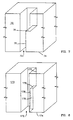
- Figure 7 is a first embodiment of a cross sectional view of a section of a connector housing having a hold-down reception space for receiving the hold-down terminal of Figure 1 in accordance with the present invention.
- Figure 8 is a second embodiment of a cross sectional view of a section of a connector housing having a hold-down reception space for receiving the hold-down terminal of Figure 3 in accordance with the present invention.
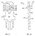
- Figure 9 is a side view of a third embodiment of a hold-down terminal in accordance with the present invention.
- Figure 10 is an edge view of the hold-down terminal of Figure 9.
- Figure 11 is a side view of a fourth embodiment of a hold-down terminal in accordance with the present invention.
- Figure 12 is an edge view of the hold-down terminal of Figure 11.
- Figure 13 is a perspective view of a connector having surface-mount terminal pins and hold-downs terminals in accordance with the present invention.
- FIG. 1 there is illustrated a side view of a first embodiment of a hold-down terminal 10 in accordance with the present invention.
- Figure 2 is an edge surface view of the hold-down terminal 10 of Figure 1.
- the hold-down terminal 10 is for holding a connector housing to a circuit assembly.
- circuit assembly is intended to include any assembly that includes a plurality of conductors, leads, plated through holes or conductive paths, pads or areas.
- the circuit assembly can be a printed wiring board or a printed circuit board, such as a backpanel, a mother board or a daughter board.
- the circuit assembly can be rigid or flexible.
- the hold-down terminal 10 comprises a housing attaching portion 12, a circuit assembly attaching portion 16 and a stand-off 14 between the housing attaching portion 12 and the circuit assembly attaching portion 16.
- the housing attaching portion 12, the circuit assembly attaching portion 16 and the stand-off 14 are preferably made from a single or one piece of material. They can be made from a single strip of metal defined by a pair of opposing sides 18 interconnected by edge surfaces.
- the housing attaching portion 12 has a spring member 20 entirely defined by areas 22 of the pair of opposing sides 18, a first edge surface 24 and a second edge surface of support surface 26.
- the first edge surface 24 and the second edge surface 26 interconnect the opposing side areas 22.
- the first edge surface 24 intersects the second edge surface 26 forming a first corner 28.
- the first corner 28 extends generally laterally with respect to the remainder of the hold-down 10.
- the opposing side areas 22 are bent with respect to the remainder of the opposing sides 18.
- the housing attaching portion 12 has a third planar edge surface 30 intersecting a fourth planar edge surface 32 forming a second corner 34.
- the housing attaching portion 12 When the housing attaching portion 12 is inserted in a space partially defined by a shoulder surface recessed in a connector housing, the housing compresses the spring member 20 until the second edge surface 26 springs onto the shoulder surface.
- One of the side areas 22 of the spring member 20 comprises an easy insertion ramp for sliding against the housing when inserted into the hold-down reception space.
- the second edge surface 26 in contact with the shoulder surface prevents withdrawal of the hold-down 10 from the housing space until the spring member 20 is compressed such as by a screw driver or other similar tool forced into the space on the shoulder surface adjacent the spring member 20.
- the housing attaching portion 12 is easily removed from the housing so the connector can be replaced or repairs can be performed.
- a single cut or shear can form both the second edge surface or support surface 26 and the third edge surface 30.
- a slug of material can be punched or stamped out forming the second edge surface 26 facing the third edge surface 30 across a gap. Then the opposing side areas 22 are bent or molded to the shape of the desired spring member 20.
- the circuit assembly attaching portion 16 is for securing to the circuit assembly.
- the circuit assembly attaching portion 16 can be described as generally having a shape of a Christmas tree.
- the circuit assembly attaching portion 16 comprises a pair of spring members 36 generally parallel to one another and spaced entirely apart by a slot 38.
- the spring members 36 are the branches of the Christmas tree.
- the spring members 36 are connected together at and extend from the stand-off 14. This connection of the spring members 36 to the stand-off 14 resembles a trunk 40 of the Christmas tree.
- the spring members 36 have outer edge surfaces comprising easy insertion ramps 42 with barbs 44 at outer ends of the ramps 42 such that the ramps 42 allow easy insertion into a hole through the circuit assembly forming an interference fit in the assembly hole. However, the barbs 44 dig into the circuit assembly if the hold-down terminal 10 is withdrawn from the hole.
- the barbs 44 resemble the ends of the branches of the Christmas tree.
- the stand-off 14 has opposed surfaces 46,48 for facing the housing and the circuit assembly.
- the stand-off 14 is for ensuring a space between the housing and the circuit assembly to limit wicking during soldering and to allow cleaning.
- One 46 of the opposing surfaces 46,48 of the stand-off 14 provides a stop for contacting the housing and preventing further insertion of the hold-down terminal 10 into the hold-down reception space.
- the opposing sides 18 of the housing attaching portion 12, the circuit assembly attaching portion 16 and the stand-off 14 are entirely in a pair of parallel planes, except for the opposing side areas 22 of the spring member 20 when in a noncompressed state.
- the opposing side areas 22 are substantially in the parallel planes with the remainder of the opposing sides 18.
- FIG. 3-6 there is illustrated a second embodiment of a hold-down terminal 110 in accordance with the present invention.
- the second hold-down terminal 110 is the same as the first hold-down terminal 10, except the second hold-down terminal 110 has a housing attaching portion 112 that is different than the housing attaching portion 12 of the first hold-down terminal 10.
- the housing attaching portion 112 comprises a flat strip having a first side 150 and a second side 152 folded upon itself forming a first portion 154, a second portion 156 and an elbow portion 158 interconnecting the first portion 154 and the second portion 156.
- the second portion 156 comprises a first section 160 and a second section 162.
- the first section 160 includes a spring member 120 entirely defined by areas 122 of the first and second sides 150,152, a first edge surface 124 and a second edge surface or support surface 126.
- the first edge surface 124 and the second edge surface 126 interconnect the side areas 122.
- the first edge surface 124 intersects the second edge surface 126 forming a first corner 128.
- the housing attaching portion 112 has a third planar edge surface 130 intersecting a fourth planar edge surface 132 forming a second corner 134.
- the first, second, third and fourth edge surfaces 24,26,30,32 are configured and function similar to the first, second, third and fourth edge surfaces 124,126,130,132, respectively.
- the first and second side areas 122 of the spring member 120 are configured and function similar to the side areas 22 of the spring member 20.
- the first side 150 of the first portion 154 substantially contacts the first side 150 of the second portion 156 except the second edge 126 extends away from the first portion 154 forming a protruding end surface of the spring member 120.
- the second edge surface or support surface 126 of the spring member 120 has a substantially U shaped cross section in its noncompressed state.
- the outer side area 122 of the spring member 120 comprises an easy insertion ramp for sliding against the housing when being inserted into the hold-down reception space recessed in the mounting face of the connector housing.
- FIG 7 is a first embodiment of a cross sectional view of a section of a connector housing 70 having a hold-down reception space 72 for receiving the hold-down terminal 10 of Figure 1 in accordance with the present invention.
- the housing 70 is made of a dielectric material. It has a mounting face 74 and the hold-down reception space 72 is recessed in the mounting face 74.
- the space 72 is partially defined by a shoulder surface 76 generally parallel to the mounting face 74. In this embodiment, the shoulder surface 76 extends the entire width of the space 72.
- This shoulder surface 76 can be described as the top surface of a step which has only one other surface 78 exposed or partially defining the space 72.
- Figure 8 is a second embodiment of a cross sectional view of a section of a connector housing 170 having a hold-down reception space 172 for receiving the hold-down terminal 110 of Figure 3 in accordance with the present invention.
- the hold-down reception space 172 illustrated in Figure 8 is the same as the hold-down reception space 172 illustrated in Figure 7 except the space 172 is partially defined by a shoulder surface 176 generally parallel to the mounting face 174 where the shoulder surface 176 does not extend the entire width of the space 172.
- the shoulder surface 176 is positioned in a corner 177 of the space 172.
- This shoulder surface 176 can be described as the top surface of a step which has two other surfaces 178,179 exposed or partially defining the space 172.
- FIG. 9 there is illustrated a third embodiment of a hold-down terminal 210 in accordance with the present invention.
- This embodiment is the same as the first hold-down terminal 10 except this hold-down terminal 210 has a housing attaching portion 212 which is different than the housing attaching portion 12 of the first hold-down terminal 10.
- the housing attaching portion 212 of this hold-down terminal 210 fits in and secures to the housing 70 defining the hold-down reception space 72 illustrated in Figure 7.
- the housing attaching portion 212 has a spring member 220 entirely defined by areas 222 of the pair of opposing sides 218, a first edge surface 224, a second edge surface or support surface 226 and a third edge surface 227.
- the first edge surface 224, the second edge surface 226 and the third edge surface 227 interconnect the opposing side areas 222.
- the first edge surface 224 intersects the second edge surface 226 forming a first corner 228.
- the second edge surface 226 intersects the third edge surface 227 forming a second corner 229. In a noncompressed state, the second edge surface or support surface 226 extends generally laterally with respect to the remainder of the hold-down terminal 210.
- the housing attaching portion 212 has a fourth edge surface 221 which intersects the third edge surface 227 at a curved junction or intersection 223.
- the fourth edge surface 221 intersects a fifth edge surface 230 forming a third rounded corner 225.
- a sixth planar edge surface 232 intersects the fifth edge surface 230 forming a fourth corner 234.
- the second edge surface or support surface 226 faces the fifth edge surface 230 across a gap
- the third edge surface 227 faces the fourth edge surface 221 across a gap
- the first edge surface 224 and the sixth edge surface 232 are coplanar and arranged end to end.
- the edge surfaces 226, 227, 221 and 230 can be formed by punching a first slug out from a strip of material forming the second edge surface 226 and the fifth edge surface 230. Another slug of material is punched out of the strip forming the third edge surface 227 and the fourth edge surface 221. Then the opposing side areas 222 are bent or molded to the shape of the desired spring member 220.
- a hold-down terminal 310 just like the first hold-down terminal 10 except this hold-down terminal 310 has a circuit assembly attaching portion 316 which is a mirror image of the housing attaching portion 12 of the first hold-down terminal 10.
- the assembly compresses a spring member 320 of the circuit assembly attaching portion 316 until an edge surface or support surface 324 of the spring member 320 of the circuit assembly attaching portion 316 springs out of the assembly hole below and onto a surface of the circuit assembly.
- the cross section of the assembly hole would preferably be rectangular.
- another hold-down terminal in accordance with the present invention is configured to have two mirror image end sections such that the housing attaching portion is as illustrated in Figures 3-6 and the circuit assembly attaching portion is its mirror image.
- Another hold-down terminal in accordance with the present invention is configured to have two mirror image end sections such that the housing attaching portion is as illustrated in Figures 9 and 10 and the circuit assembly attaching portion is its mirror image.
- the housing attaching portions disclosed herein will allow an easy release of the housing attaching portion from the connector housing and when used as a circuit assembly attaching portion will allow an easy release of the circuit assembly attaching portion from the circuit assembly. Thus, they can be used to hold down a connector to a circuit assembly and they also allow parts to be removed to permit repairs or exchange of parts.
- the hold-down terminals disclosed herein require a minimum of space in the connector housing and on the circuit assembly surface.
- FIG. 13 is a perspective view of a connector 400 having surface-mount terminal pins 402 and hold-downs terminals 410 in accordance with the present invention which are distinct from the surface mount pins or contact elements 402.
- the hold-downs terminals or hold-downs of the present invention can be made from any suitable metal used for making hold-downs, such as stainless steel. Further, the hold-downs can be made from any suitable metal used for making electrical terminals, such as brass, phosphor bronze, beryllium copper and the like. The hold-down may be plated or coated with a layer, such as tin, lead, nickel, palladium, gold, silver or a suitable alloy.
Landscapes
- Coupling Device And Connection With Printed Circuit (AREA)
- Connector Housings Or Holding Contact Members (AREA)
- Multi-Conductor Connections (AREA)
Description
- This invention relates to hold-downs for securing components to circuit assemblies and more particularly to hold-down terminals for securing connectors to printed circuit boards.
- Various apparatus exist for locating and securing connectors onto printed circuit boards (PCBs) prior to and during soldering of electrical terminals mounted in the connector to the circuit assembly.
- For instance, U.S. Patent 4,735,587 discloses a header with two rows of pins with selected opposed pin pairs having cantilever retention arms for engaging interior surfaces of circuit board holes to hold the header to a circuit board prior to and during soldering. The pins are held in the board holes merely by the interference fit between linear corners or edges of the pins against the wall of the board holes. The particular shape and orientation of the retention arms results in the need for a relatively high insertion force in order to press the pin into a hole.
- US-A-4 907 987 (equivalent to EP-A-0 366 964) discloses a boardlock for mounting a connector to a printed circuit board. A first portion of the boardlock is secured by an interference fit within a recess in the connector housing. Tabs define shoulders on the boardlock which prevent the housing from being separated from the boardlock. A pair of spring members extend from the first portion for insertion into a hole through the circuit board. Barbs on opposed surfaces of the spring members bite into the wall of the hole forming an interference fit between the boardlock and the circuit board. However, the retention force caused by the interference fit between this hold-down in a connector housing is low which may necessitate the use of a special seating tool to connect such a hold-down to a board.
- It is an object of this invention to provide a hold-down terminal that can be used to hold down a connector on a printed circuit board at least while terminals mounted in the connector are soldered to the circuit board.
- It is an object of this invention to provide the hold-down terminal such that it can be used to hold down either a through-mount connector or a surface mount connector onto a printed circuit board.
- The and other objects of the invention will be clear from the following description.
- As is known from US-A-4907987, the invention relates to a hold-down terminal for holding a component, such as a connector housing, to a circuit assembly the component having a mounting face and a hold-down reception space recessed in the mounting face, the space being partially defined by a shoulder surface generally parallel to the mounting face; the hold-down terminal comprising: a housing attaching portion and a circuit assembly attaching portion for securing to the circuit assembly,
- In accordance with the invention the housing attaching portion has a spring member with a support surface such that when the housing attaching portion is inserted in the reception space the spring member is compressed until the support surface springs onto the shoulder surface partially defining the space and there is a stand-off between the housing attaching portion and the circuit assembly attaching portion, the stand-off having opposed surfaces for facing the housing and the circuit assembly and for ensuring a space is present between the housing and the circuit assembly to limit wicking during soldering and to allow cleaning
- The shape of the spring member is such as to form an easy insertion ramp to aid insertion of the housing attaching portion into the reception space of the component.
- The housing attaching portion, circuit assembly attaching portion and the stand-offs can all be made in one piece.
- In one embodiment the housing attaching portion, the circuit assembly attaching portion and the stand-off of the hold down terminal have opposed sides which are entirely in a pair of parallel planes when the spring member is in a compressed state but not when it is in a non-compressed state.
- In another embodiment the housing attaching portion is made from a flat strip folded upon itself to form a first portion and a second portion joined by an elbow portion. The second portion can comprise a first section and a second section partially divided to form the support surface on the first section and another edge surface on the second section. The first portion and second portion substantially contact each other except where the support surface extends away from the first portion and protrudes from the remainder of the housing attaching portion.
- In a further embodiment the housing attaching portion and the spring member combine to define a generally U-shaped cross section in the non-compressed state of the spring member.
- The spring member may be spaced from the remainder of the housing attaching portion when in its compressed state. The spring member can also have two further edge surfaces in a configuration where in the compressed state the support surface and the two further edge surfaces are spaced from the remainder of the housing attaching portion.
- The circuit assembly attaching portion of the hold down terminal can be a mirror image of the housing attaching portion but in an alternative construction the circuit assembly attaching portion comprises a pair of spring members generally parallel to one another and spaced entirely apart by a slot, except where the spring members are connected together at the end from the stand-off The spring members have outer sides comprising easy insertion rams with barbs at their outer ends of the ramps. The ramps allow easy insertion to form an interference fit in a hole through the circuit assembly. If the hold-down terminal is withdraw from the hole, the barbs dig into the circuit assembly to resist removal.
- According to another optional feature of the invention one of the opposing surfaces of the stand-off provides a stop for contacting the housing and preventing further insertion of the hold-down terminal into the reception space.
- The invention can be more fully understood from the following detailed description thereof in connection with accompanying drawings described as follows.
- Figure 1 is a side view of a first embodiment of a hold-down terminal in accordance with the present invention.
- Figure 2 is an edge view of the hold-down terminal of Figure 1.
- Figure 3 is a side view of a second embodiment of a hold-down terminal in accordance with the present invention.
- Figure 4 is a cross sectional view taken along line A-A in Figure 3 generally in the direction of the arrows.
- Figure 5 is an edge view of the hold-down terminal of Figure 3.
- Figure 6 is a cross sectional view taken along line B-B in Figure 5 generally in the direction of the arrows.
- Figure 7 is a first embodiment of a cross sectional view of a section of a connector housing having a hold-down reception space for receiving the hold-down terminal of Figure 1 in accordance with the present invention.
- Figure 8 is a second embodiment of a cross sectional view of a section of a connector housing having a hold-down reception space for receiving the hold-down terminal of Figure 3 in accordance with the present invention.
- Figure 9 is a side view of a third embodiment of a hold-down terminal in accordance with the present invention.
- Figure 10 is an edge view of the hold-down terminal of Figure 9.
- Figure 11 is a side view of a fourth embodiment of a hold-down terminal in accordance with the present invention.
- Figure 12 is an edge view of the hold-down terminal of Figure 11.
- Figure 13 is a perspective view of a connector having surface-mount terminal pins and hold-downs terminals in accordance with the present invention.
- Throughout the following detailed description, similar reference characters refer to similar elements in all figures of the drawings.
- Referring to Figure 1, there is illustrated a side view of a first embodiment of a hold-
down terminal 10 in accordance with the present invention. Figure 2 is an edge surface view of the hold-downterminal 10 of Figure 1. - The hold-
down terminal 10 is for holding a connector housing to a circuit assembly. The term "circuit assembly" is intended to include any assembly that includes a plurality of conductors, leads, plated through holes or conductive paths, pads or areas. The circuit assembly can be a printed wiring board or a printed circuit board, such as a backpanel, a mother board or a daughter board. The circuit assembly can be rigid or flexible. - The hold-
down terminal 10 comprises ahousing attaching portion 12, a circuitassembly attaching portion 16 and a stand-off 14 between thehousing attaching portion 12 and the circuitassembly attaching portion 16. Thehousing attaching portion 12, the circuitassembly attaching portion 16 and the stand-off 14 are preferably made from a single or one piece of material. They can be made from a single strip of metal defined by a pair ofopposing sides 18 interconnected by edge surfaces. - The
housing attaching portion 12 has aspring member 20 entirely defined byareas 22 of the pair ofopposing sides 18, afirst edge surface 24 and a second edge surface ofsupport surface 26. Thefirst edge surface 24 and thesecond edge surface 26 interconnect theopposing side areas 22. Thefirst edge surface 24 intersects thesecond edge surface 26 forming afirst corner 28. In a noncompressed state, thefirst corner 28 extends generally laterally with respect to the remainder of the hold-down 10. In other words, theopposing side areas 22 are bent with respect to the remainder of theopposing sides 18. Thehousing attaching portion 12 has a thirdplanar edge surface 30 intersecting a fourthplanar edge surface 32 forming asecond corner 34. In a compressed state where the opposingside areas 22 are forced to substantially be coplanar with the remainder of the opposingsides 18, then (1) thesecond edge surface 26 faces thethird edge surface 30 and (2) thefirst edge surface 24 and thefourth edge surface 32 are coplanar and arranged end to end. When thehousing attaching portion 12 is inserted in a space partially defined by a shoulder surface recessed in a connector housing, the housing compresses thespring member 20 until thesecond edge surface 26 springs onto the shoulder surface. One of theside areas 22 of thespring member 20 comprises an easy insertion ramp for sliding against the housing when inserted into the hold-down reception space. Thesecond edge surface 26 in contact with the shoulder surface prevents withdrawal of the hold-down 10 from the housing space until thespring member 20 is compressed such as by a screw driver or other similar tool forced into the space on the shoulder surface adjacent thespring member 20. By this action, thehousing attaching portion 12 is easily removed from the housing so the connector can be replaced or repairs can be performed. - A single cut or shear can form both the second edge surface or
support surface 26 and thethird edge surface 30. Alternatively, a slug of material can be punched or stamped out forming thesecond edge surface 26 facing thethird edge surface 30 across a gap. Then the opposingside areas 22 are bent or molded to the shape of the desiredspring member 20. - The circuit
assembly attaching portion 16 is for securing to the circuit assembly. The circuitassembly attaching portion 16 can be described as generally having a shape of a Christmas tree. The circuitassembly attaching portion 16 comprises a pair ofspring members 36 generally parallel to one another and spaced entirely apart by aslot 38. Thespring members 36 are the branches of the Christmas tree. Thespring members 36 are connected together at and extend from the stand-off 14. This connection of thespring members 36 to the stand-off 14 resembles atrunk 40 of the Christmas tree. Thespring members 36 have outer edge surfaces comprising easy insertion ramps 42 withbarbs 44 at outer ends of theramps 42 such that theramps 42 allow easy insertion into a hole through the circuit assembly forming an interference fit in the assembly hole. However, thebarbs 44 dig into the circuit assembly if the hold-downterminal 10 is withdrawn from the hole. Thebarbs 44 resemble the ends of the branches of the Christmas tree. - The stand-
off 14 has opposedsurfaces off 14 is for ensuring a space between the housing and the circuit assembly to limit wicking during soldering and to allow cleaning. One 46 of the opposingsurfaces off 14 provides a stop for contacting the housing and preventing further insertion of the hold-down terminal 10 into the hold-down reception space. - The opposing sides 18 of the
housing attaching portion 12, the circuitassembly attaching portion 16 and the stand-off 14 are entirely in a pair of parallel planes, except for the opposingside areas 22 of thespring member 20 when in a noncompressed state. When thespring member 20 is in a compressed state, the opposingside areas 22 are substantially in the parallel planes with the remainder of the opposing sides 18. - Referring to Figures 3-6, there is illustrated a second embodiment of a hold-down terminal 110 in accordance with the present invention. The second hold-down
terminal 110 is the same as the first hold-down terminal 10, except the second hold-downterminal 110 has ahousing attaching portion 112 that is different than thehousing attaching portion 12 of the first hold-downterminal 10. - The
housing attaching portion 112 comprises a flat strip having afirst side 150 and asecond side 152 folded upon itself forming afirst portion 154, asecond portion 156 and anelbow portion 158 interconnecting thefirst portion 154 and thesecond portion 156. Thesecond portion 156 comprises afirst section 160 and asecond section 162. Thefirst section 160 includes aspring member 120 entirely defined by areas 122 of the first and second sides 150,152, afirst edge surface 124 and a second edge surface orsupport surface 126. Thefirst edge surface 124 and thesecond edge surface 126 interconnect the side areas 122. Thefirst edge surface 124 intersects thesecond edge surface 126 forming afirst corner 128. Thehousing attaching portion 112 has a thirdplanar edge surface 130 intersecting a fourthplanar edge surface 132 forming asecond corner 134. The first, second, third and fourth edge surfaces 24,26,30,32 are configured and function similar to the first, second, third and fourth edge surfaces 124,126,130,132, respectively. Similarly, the first and second side areas 122 of thespring member 120 are configured and function similar to theside areas 22 of thespring member 20. Thefirst side 150 of thefirst portion 154 substantially contacts thefirst side 150 of thesecond portion 156 except thesecond edge 126 extends away from thefirst portion 154 forming a protruding end surface of thespring member 120. Referring to Figure 6, the second edge surface orsupport surface 126 of thespring member 120 has a substantially U shaped cross section in its noncompressed state. The outer side area 122 of thespring member 120 comprises an easy insertion ramp for sliding against the housing when being inserted into the hold-down reception space recessed in the mounting face of the connector housing. - Figure 7 is a first embodiment of a cross sectional view of a section of a
connector housing 70 having a hold-down reception space 72 for receiving the hold-downterminal 10 of Figure 1 in accordance with the present invention. Thehousing 70 is made of a dielectric material. It has a mountingface 74 and the hold-down reception space 72 is recessed in the mountingface 74. Thespace 72 is partially defined by ashoulder surface 76 generally parallel to the mountingface 74. In this embodiment, theshoulder surface 76 extends the entire width of thespace 72. Thisshoulder surface 76 can be described as the top surface of a step which has only oneother surface 78 exposed or partially defining thespace 72. - Figure 8 is a second embodiment of a cross sectional view of a section of a
connector housing 170 having a hold-down reception space 172 for receiving the hold-downterminal 110 of Figure 3 in accordance with the present invention. The hold-down reception space 172 illustrated in Figure 8 is the same as the hold-down reception space 172 illustrated in Figure 7 except thespace 172 is partially defined by ashoulder surface 176 generally parallel to the mountingface 174 where theshoulder surface 176 does not extend the entire width of thespace 172. In this embodiment, theshoulder surface 176 is positioned in acorner 177 of thespace 172. Thisshoulder surface 176 can be described as the top surface of a step which has two other surfaces 178,179 exposed or partially defining thespace 172. - Referring to Figures 9 and 10, there is illustrated a third embodiment of a hold-down terminal 210 in accordance with the present invention. This embodiment is the same as the first hold-down terminal 10 except this hold-down
terminal 210 has a housing attaching portion 212 which is different than thehousing attaching portion 12 of the first hold-downterminal 10. However, like thehousing attaching portion 10 of the first hold-down terminal 10, the housing attaching portion 212 of this hold-down terminal 210 fits in and secures to thehousing 70 defining the hold-down reception space 72 illustrated in Figure 7. - The housing attaching portion 212 has a
spring member 220 entirely defined byareas 222 of the pair of opposingsides 218, afirst edge surface 224, a second edge surface orsupport surface 226 and athird edge surface 227. Thefirst edge surface 224, thesecond edge surface 226 and thethird edge surface 227 interconnect the opposingside areas 222. Thefirst edge surface 224 intersects thesecond edge surface 226 forming afirst corner 228. Thesecond edge surface 226 intersects thethird edge surface 227 forming asecond corner 229. In a noncompressed state, the second edge surface orsupport surface 226 extends generally laterally with respect to the remainder of the hold-downterminal 210. In other words, the opposingside areas 222 are bent with respect to the remainder of the opposing sides 218. The housing attaching portion 212 has afourth edge surface 221 which intersects thethird edge surface 227 at a curved junction orintersection 223. Thefourth edge surface 221 intersects afifth edge surface 230 forming a thirdrounded corner 225. A sixthplanar edge surface 232 intersects thefifth edge surface 230 forming afourth corner 234. In a compressed state where the opposingside areas 222 are forced to be substantially coplanar with the remainder of the opposingsides 218, then (1) the second edge surface orsupport surface 226 faces thefifth edge surface 230 across a gap, (2) thethird edge surface 227 faces thefourth edge surface 221 across a gap, and (3) thefirst edge surface 224 and thesixth edge surface 232 are coplanar and arranged end to end. - The edge surfaces 226, 227, 221 and 230 can be formed by punching a first slug out from a strip of material forming the
second edge surface 226 and thefifth edge surface 230. Another slug of material is punched out of the strip forming thethird edge surface 227 and thefourth edge surface 221. Then the opposingside areas 222 are bent or molded to the shape of the desiredspring member 220. - Referring to Figures 11 and 12, there is illustrated a hold-down terminal 310 just like the first hold-down terminal 10 except this hold-down
terminal 310 has a circuitassembly attaching portion 316 which is a mirror image of thehousing attaching portion 12 of the first hold-downterminal 10. With this hold-downterminal 310 when the circuitassembly attaching portion 316 is inserted in a hole through the circuit assembly, the assembly compresses aspring member 320 of the circuitassembly attaching portion 316 until an edge surface orsupport surface 324 of thespring member 320 of the circuitassembly attaching portion 316 springs out of the assembly hole below and onto a surface of the circuit assembly. The cross section of the assembly hole would preferably be rectangular. - It should be noted that another hold-down terminal in accordance with the present invention is configured to have two mirror image end sections such that the housing attaching portion is as illustrated in Figures 3-6 and the circuit assembly attaching portion is its mirror image. Another hold-down terminal in accordance with the present invention is configured to have two mirror image end sections such that the housing attaching portion is as illustrated in Figures 9 and 10 and the circuit assembly attaching portion is its mirror image.
- Alternatively, it is within the scope of the present invention to make a hold-down terminal with any one of the housing attaching portions disclosed herein connected to a stand-off which in turn is connected to any one of the circuit assembly attaching portions disclosed herein.
- The housing attaching portions disclosed herein will allow an easy release of the housing attaching portion from the connector housing and when used as a circuit assembly attaching portion will allow an easy release of the circuit assembly attaching portion from the circuit assembly. Thus, they can be used to hold down a connector to a circuit assembly and they also allow parts to be removed to permit repairs or exchange of parts. The hold-down terminals disclosed herein require a minimum of space in the connector housing and on the circuit assembly surface.
- The hold-down terminals of the present invention can be used to secure surface-mount connectors or through mount connectors to circuit assemblies. In either case, the hold-downs of the present invention can be used to ground the connector to the assembly. Typically, the hold-down terminals will be in addition to and distinct from the electrical contact elements used as signal paths. Figure 13 is a perspective view of a
connector 400 having surface-mount terminal pins 402 and hold-downs terminals 410 in accordance with the present invention which are distinct from the surface mount pins or contactelements 402. - The hold-downs terminals or hold-downs of the present invention can be made from any suitable metal used for making hold-downs, such as stainless steel. Further, the hold-downs can be made from any suitable metal used for making electrical terminals, such as brass, phosphor bronze, beryllium copper and the like. The hold-down may be plated or coated with a layer, such as tin, lead, nickel, palladium, gold, silver or a suitable alloy.
- Those skilled in the art, having the benefit of the teachings of the present invention as hereinabove set forth, can effect numerous modifications thereto. These modifications are to be construed as being encompassed within the scope of the present invention as set forth in the appended claims.
Claims (11)
- A hold-down terminal (10,110,210,310) for holding a component, such as a connector housing, to a circuit assembly, the component having a mounting face (74,174) and a hold-down receiving space (72,172) recessed in the mounting face, the space being partially defined by a shoulder surface (76,176) generally parallel to the mounting face; said hold-down terminal comprising: a housing attaching portion (12,112,212) and a circuit assembly attaching portion (16,316)
characterised in that: the housing attaching portion (12,112,212) has a spring member (20,120,220) with a support surface (26,126,226) such that when the housing attaching portion is inserted in the reception space the spring member is compressed until the support surface springs onto the shoulder surface partially defining the space and there is a stand-off (14) between the housing attaching portion and the circuit assembly attaching portion, the stand-off having opposed surfaces (46,48) for facing the housing and the circuit assembly and for ensuring a space is present between the housing and the circuit assembly to limit wicking during soldering and to allow cleaning. - The hold-down terminal of claim 1, wherein the circuit assembly attaching portion comprises a pair of spring members (36) generally parallel to one another and spaced entirely apart by a slot (38) except where the spring members are connected together at and extend from the stand-off (14), where the spring members (36) have outer sides comprising easy insertion ramps (42) with barbs (44) at outer ends of the ramps such that the ramps allow easy insertion forming an interference fit in a hole through the circuit assembly, but the barbs dig into the circuit assembly if the hold-down terminal is withdrawn from the hole.
- The hold-down terminal of claim 1, wherein the circuit assembly attaching portion (316) is a mirror image of the housing attaching portion (12,212) when the circuit assembly attaching portion (316) is inserted in a hole through the circuit assembly, the assembly compresses an associated spring member (320) of the circuit assembly attaching portion (316) until the support surface (324) of the associated spring member (320) of the circuit assembly attaching portion springs out of the assembly hole onto a surface of the circuit assembly.
- The hold-down terminal of any one of claims 1 or 3 wherein the housing attaching portion (112) and the spring member (120) combine to define a generally U-shaped cross-section in the non-compressed state of the spring member.
- The hold-down terminal of any one of claims 1 to 3 wherein the housing attaching portion (112) comprises a flat strip having a first side (150) and a second side (152) folded upon itself forming a first portion (154), a second portion (156) and an elbow portion (158) interconnecting the first portion (154) and the second portion (156), the second portion (156) comprises a first section (160) and a second section (162) partially divided to form the said support surface (126) on the first section (160) and another edge surface (130) on the second section (162), the first side (150) of the first portion (154) substantially contacting the first side (150) of the second portion (156) except where the said support surface (126) extends away from the first portion (154) so as to protrude from the remainder of the housing attaching portion.
- The hold-down terminal of any one of claims 1 to 3, wherein the housing attaching portion (12,212), the circuit assembly attaching portion (16,316) and the stand-off (14) have opposed sides (18,218) entirely in a pair of parallel planes, except the or each spring member (20,220,320) which has opposed side areas (22,222) that are substantially in the parallel planes when the spring member (20,220,320) is in a compressed state but not in the parallel planes when the spring member (20,220) is in a non-compressed state.
- The hold-down terminal of any one of claims 1,2,3 or 6, wherein in the compressed state the support surface (26) of the spring member (20) is spaced from the remainder of the housing attaching portion.
- The hold-down terminal of any one of claims 1 to 4 wherein the spring member (220) has two further edge surfaces (224,227) and in the compressed state the support surface (226) and the two further edge surfaces (224,227) of the spring member (220) are spaced from the remainder of the housing attaching portion (212).
- The hold-down terminal of any one of claims 1 to 8, wherein the housing attaching portion (12,112,212), the circuit assembly attaching portion (16,316) and the stand-off (14) are one-piece.
- The hold-down terminal of any one of claims 1 to 9, wherein one of the opposing surfaces (46) of the stand-off (14) provides a stop for contacting the housing and preventing further insertion of the hold-down terminal into the reception space.
- An electrical connector for mounting to a circuit assembly, comprising:a dielectric housing (70,170) having a mounting face (74) and a hold-down reception space (72,172) recessed in the mounting face, the space being partially defined by a shoulder surface (76, 176) generally parallel to the mounting face, anda hold-down terminal according to any one of the preceding claims which has its housing attaching portion inserted in the space (72,172) in the housing until its support surface engages on the shoulder surface (76,176).
Applications Claiming Priority (2)
| Application Number | Priority Date | Filing Date | Title |
|---|---|---|---|
| US647643 | 1991-01-29 | ||
| US07/647,643 US5135412A (en) | 1991-01-29 | 1991-01-29 | Hold-down terminal |
Publications (2)
| Publication Number | Publication Date |
|---|---|
| EP0497554A1 EP0497554A1 (en) | 1992-08-05 |
| EP0497554B1 true EP0497554B1 (en) | 1996-12-18 |
Family
ID=24597756
Family Applications (1)
| Application Number | Title | Priority Date | Filing Date |
|---|---|---|---|
| EP92300715A Expired - Lifetime EP0497554B1 (en) | 1991-01-29 | 1992-01-28 | Hold-down terminal |
Country Status (8)
| Country | Link |
|---|---|
| US (1) | US5135412A (en) |
| EP (1) | EP0497554B1 (en) |
| JP (1) | JPH0547427A (en) |
| KR (1) | KR100211272B1 (en) |
| AU (1) | AU1038592A (en) |
| CA (1) | CA2059393A1 (en) |
| DE (1) | DE69215917T2 (en) |
| HK (1) | HK63797A (en) |
Families Citing this family (18)
| Publication number | Priority date | Publication date | Assignee | Title |
|---|---|---|---|---|
| AU2264192A (en) * | 1992-03-13 | 1993-10-05 | Itt Industries, Inc. | Holdown key for low profile connector |
| US5228870A (en) * | 1992-07-30 | 1993-07-20 | Amp Incorporated | Connector to circuit board securing arrangement with holding device insertion depth compensator |
| US6280248B1 (en) | 1993-04-19 | 2001-08-28 | Berg Technology, Inc. | Hold-down element for electrical and/or electronic components |
| US5336111A (en) * | 1993-09-28 | 1994-08-09 | The Whitaker Corporation | Boardlock for an electrical connector |
| US5419713A (en) * | 1993-12-06 | 1995-05-30 | Berg Electronics | Electrical connector with self-retained boardlock |
| US5393247A (en) * | 1994-03-23 | 1995-02-28 | The Whitaker Corporation | Component mounting device |
| US5478257A (en) * | 1994-04-07 | 1995-12-26 | Burndy Corporation | Retention device |
| JPH10500248A (en) * | 1994-05-10 | 1998-01-06 | バーグ・テクノロジー・インコーポレーテッド | Multiple hooks holddown |
| US5489219A (en) * | 1994-05-24 | 1996-02-06 | The Whitaker Corporation | Self-retaining board lock |
| US5601453A (en) * | 1994-07-20 | 1997-02-11 | Berg Technology, Inc. | Electrical connector hold-down |
| US5575663A (en) * | 1994-11-29 | 1996-11-19 | The Whitaker Corporation | Electrical connector for mounting to an edge of a circuit board |
| US5664965A (en) * | 1996-03-29 | 1997-09-09 | Berg Technology, Inc. | Device for fixing an electrical connector to a printed circuit board |
| US5803765A (en) * | 1996-04-02 | 1998-09-08 | Molex Incorporated | Electrical connector with universal boardlock |
| US5868587A (en) * | 1997-02-20 | 1999-02-09 | The Whitaker Corporation | Component mounting device |
| TW419142U (en) * | 1999-02-09 | 2001-01-11 | Hon Hai Prec Ind Co Ltd | Electrical connector |
| JP2008059856A (en) * | 2006-08-30 | 2008-03-13 | Sumitomo Wiring Syst Ltd | Board connector |
| JP2008123966A (en) * | 2006-11-15 | 2008-05-29 | Auto Network Gijutsu Kenkyusho:Kk | Board connector |
| CN103457116A (en) * | 2013-08-30 | 2013-12-18 | 徐州华夏电子有限公司 | Improved power socket fixing insertion piece |
Family Cites Families (12)
| Publication number | Priority date | Publication date | Assignee | Title |
|---|---|---|---|---|
| FR1408761A (en) * | 1964-06-26 | 1965-08-20 | Souriau & Cie | Improvements to connectors, especially for printed circuits |
| US3902777A (en) * | 1974-05-16 | 1975-09-02 | Itt | Electrical connector assembly |
| FR2315781A1 (en) * | 1975-06-27 | 1977-01-21 | Socapex | FIXING DEVICE FOR ELECTRICAL CONNECTOR AND CONNECTOR EQUIPPED WITH SUCH A DEVICE |
| FR2353970A1 (en) * | 1976-06-03 | 1977-12-30 | Chauchat Jean | Thin panel mounting for rectangular electronic components - uses sprung clip gripping component and having arrow head ends passing through circuit board |
| US4220393A (en) * | 1977-02-22 | 1980-09-02 | Elfab Corporation | Electrical connector and method of fabrication and assembly |
| US4619495A (en) * | 1982-09-07 | 1986-10-28 | Sochor Jerzy R | High-density press-fit cardedge connectors |
| JPH0218527Y2 (en) * | 1985-04-04 | 1990-05-23 | ||
| US4645287A (en) * | 1985-09-09 | 1987-02-24 | Amp Incorporated | Surface mount connector |
| US4735587A (en) * | 1986-02-12 | 1988-04-05 | Specialty Electronics, Inc. | Pin header with board retention tail |
| US4907987A (en) * | 1988-11-04 | 1990-03-13 | Amp Incorporated | Connector with barbed boardlock |
| US4993975A (en) * | 1989-07-07 | 1991-02-19 | Amp Incorporated | Electrical connector and tapered fixed beam contact therefor |
| JP2508076Y2 (en) * | 1989-08-24 | 1996-08-21 | 日本エー・エム・ピー株式会社 | connector |
-
1991
- 1991-01-29 US US07/647,643 patent/US5135412A/en not_active Expired - Fee Related
-
1992
- 1992-01-15 CA CA002059393A patent/CA2059393A1/en not_active Abandoned
- 1992-01-22 AU AU10385/92A patent/AU1038592A/en not_active Abandoned
- 1992-01-28 EP EP92300715A patent/EP0497554B1/en not_active Expired - Lifetime
- 1992-01-28 KR KR1019920001189A patent/KR100211272B1/en not_active Expired - Fee Related
- 1992-01-28 DE DE69215917T patent/DE69215917T2/en not_active Expired - Fee Related
- 1992-01-29 JP JP4014142A patent/JPH0547427A/en active Pending
-
1997
- 1997-05-15 HK HK63797A patent/HK63797A/en not_active IP Right Cessation
Also Published As
| Publication number | Publication date |
|---|---|
| JPH0547427A (en) | 1993-02-26 |
| DE69215917D1 (en) | 1997-01-30 |
| KR920015662A (en) | 1992-08-27 |
| KR100211272B1 (en) | 1999-07-15 |
| US5135412A (en) | 1992-08-04 |
| CA2059393A1 (en) | 1992-07-30 |
| DE69215917T2 (en) | 1997-04-03 |
| EP0497554A1 (en) | 1992-08-05 |
| AU1038592A (en) | 1992-08-06 |
| HK63797A (en) | 1997-05-23 |
Similar Documents
| Publication | Publication Date | Title |
|---|---|---|
| US5135412A (en) | Hold-down terminal | |
| EP0411888B1 (en) | Electrical connector | |
| US5112233A (en) | Electrical connector having contact retention means | |
| US4050769A (en) | Electrical connector | |
| EP0280449B1 (en) | Surface mount electrical connector | |
| JP3019997B2 (en) | Surface mount type electrical connector | |
| US4264114A (en) | Electrical connector assembly | |
| EP0602443A2 (en) | Printed circuit board mounting device for electrical connectors | |
| US5496182A (en) | Connector device for electrically interconnecting printed circuit board like members | |
| JPH0613134A (en) | Connector with ground bus | |
| EP0658958A2 (en) | Multi-piece housing card edge connector with mounting arms | |
| EP0854549A2 (en) | Surface mount connector with integrated PCB assembly | |
| EP0693796A1 (en) | Connector provided with metal strips as contact members, connector assembly comprising such a connector | |
| EP0499431B1 (en) | Lanced hold-downs | |
| WO1997045896A1 (en) | Surface mountable electrical connector | |
| EP0709931A2 (en) | Surface mountable board edge connector | |
| EP0632549B1 (en) | Electrical connector assembly | |
| US4708416A (en) | Electrical connecting terminal for a connector | |
| CA1203589A (en) | Solderless circuit board connector | |
| US7112072B2 (en) | Ground bus for an electrical connector | |
| US5836780A (en) | Card edge connector | |
| JPH11502053A (en) | Electrical receptacle assembly and spring contact therefor | |
| EP0499436B1 (en) | Fish hook hold-downs | |
| US6475031B1 (en) | Electrical connector having improved retention devices | |
| US5967806A (en) | Electrical connector arrangement |
Legal Events
| Date | Code | Title | Description |
|---|---|---|---|
| PUAI | Public reference made under article 153(3) epc to a published international application that has entered the european phase |
Free format text: ORIGINAL CODE: 0009012 |
|
| AK | Designated contracting states |
Kind code of ref document: A1 Designated state(s): DE FR GB IT NL |
|
| 17P | Request for examination filed |
Effective date: 19920617 |
|
| RIN1 | Information on inventor provided before grant (corrected) |
Inventor name: SITZLER, FRED CHRISTIAN |
|
| 17Q | First examination report despatched |
Effective date: 19941222 |
|
| GRAG | Despatch of communication of intention to grant |
Free format text: ORIGINAL CODE: EPIDOS AGRA |
|
| GRAH | Despatch of communication of intention to grant a patent |
Free format text: ORIGINAL CODE: EPIDOS IGRA |
|
| RAP1 | Party data changed (applicant data changed or rights of an application transferred) |
Owner name: CONNECTOR SYSTEMS TECHNOLOGY N.V. Owner name: BERG ELECTRONICS MANUFACTURING B.V. |
|
| GRAH | Despatch of communication of intention to grant a patent |
Free format text: ORIGINAL CODE: EPIDOS IGRA |
|
| GRAA | (expected) grant |
Free format text: ORIGINAL CODE: 0009210 |
|
| AK | Designated contracting states |
Kind code of ref document: B1 Designated state(s): DE FR GB IT NL |
|
| PG25 | Lapsed in a contracting state [announced via postgrant information from national office to epo] |
Ref country code: IT Free format text: LAPSE BECAUSE OF FAILURE TO SUBMIT A TRANSLATION OF THE DESCRIPTION OR TO PAY THE FEE WITHIN THE PRESCRIBED TIME-LIMIT;WARNING: LAPSES OF ITALIAN PATENTS WITH EFFECTIVE DATE BEFORE 2007 MAY HAVE OCCURRED AT ANY TIME BEFORE 2007. THE CORRECT EFFECTIVE DATE MAY BE DIFFERENT FROM THE ONE RECORDED. Effective date: 19961218 Ref country code: NL Free format text: LAPSE BECAUSE OF FAILURE TO SUBMIT A TRANSLATION OF THE DESCRIPTION OR TO PAY THE FEE WITHIN THE PRESCRIBED TIME-LIMIT Effective date: 19961218 |
|
| ET | Fr: translation filed | ||
| REF | Corresponds to: |
Ref document number: 69215917 Country of ref document: DE Date of ref document: 19970130 |
|
| NLV1 | Nl: lapsed or annulled due to failure to fulfill the requirements of art. 29p and 29m of the patents act | ||
| PLBE | No opposition filed within time limit |
Free format text: ORIGINAL CODE: 0009261 |
|
| 26N | No opposition filed | ||
| REG | Reference to a national code |
Ref country code: GB Ref legal event code: 732E |
|
| PGFP | Annual fee paid to national office [announced via postgrant information from national office to epo] |
Ref country code: FR Payment date: 20010122 Year of fee payment: 10 |
|
| PGFP | Annual fee paid to national office [announced via postgrant information from national office to epo] |
Ref country code: GB Payment date: 20010124 Year of fee payment: 10 |
|
| PGFP | Annual fee paid to national office [announced via postgrant information from national office to epo] |
Ref country code: DE Payment date: 20010131 Year of fee payment: 10 |
|
| REG | Reference to a national code |
Ref country code: GB Ref legal event code: IF02 |
|
| PG25 | Lapsed in a contracting state [announced via postgrant information from national office to epo] |
Ref country code: GB Free format text: LAPSE BECAUSE OF NON-PAYMENT OF DUE FEES Effective date: 20020128 |
|
| PG25 | Lapsed in a contracting state [announced via postgrant information from national office to epo] |
Ref country code: DE Free format text: LAPSE BECAUSE OF NON-PAYMENT OF DUE FEES Effective date: 20020801 |
|
| GBPC | Gb: european patent ceased through non-payment of renewal fee |
Effective date: 20020128 |
|
| PG25 | Lapsed in a contracting state [announced via postgrant information from national office to epo] |
Ref country code: FR Free format text: LAPSE BECAUSE OF NON-PAYMENT OF DUE FEES Effective date: 20020930 |
|
| REG | Reference to a national code |
Ref country code: FR Ref legal event code: ST |