EP0709931A2 - Surface mountable board edge connector - Google Patents
Surface mountable board edge connector Download PDFInfo
- Publication number
- EP0709931A2 EP0709931A2 EP95307451A EP95307451A EP0709931A2 EP 0709931 A2 EP0709931 A2 EP 0709931A2 EP 95307451 A EP95307451 A EP 95307451A EP 95307451 A EP95307451 A EP 95307451A EP 0709931 A2 EP0709931 A2 EP 0709931A2
- Authority
- EP
- European Patent Office
- Prior art keywords
- board
- connector
- positions
- contact sections
- edge
- Prior art date
- Legal status (The legal status is an assumption and is not a legal conclusion. Google has not performed a legal analysis and makes no representation as to the accuracy of the status listed.)
- Ceased
Links
Images


Classifications
-
- H—ELECTRICITY
- H01—ELECTRIC ELEMENTS
- H01R—ELECTRICALLY-CONDUCTIVE CONNECTIONS; STRUCTURAL ASSOCIATIONS OF A PLURALITY OF MUTUALLY-INSULATED ELECTRICAL CONNECTING ELEMENTS; COUPLING DEVICES; CURRENT COLLECTORS
- H01R12/00—Structural associations of a plurality of mutually-insulated electrical connecting elements, specially adapted for printed circuits, e.g. printed circuit boards [PCB], flat or ribbon cables, or like generally planar structures, e.g. terminal strips, terminal blocks; Coupling devices specially adapted for printed circuits, flat or ribbon cables, or like generally planar structures; Terminals specially adapted for contact with, or insertion into, printed circuits, flat or ribbon cables, or like generally planar structures
- H01R12/70—Coupling devices
- H01R12/71—Coupling devices for rigid printing circuits or like structures
- H01R12/72—Coupling devices for rigid printing circuits or like structures coupling with the edge of the rigid printed circuits or like structures
- H01R12/721—Coupling devices for rigid printing circuits or like structures coupling with the edge of the rigid printed circuits or like structures cooperating directly with the edge of the rigid printed circuits
Definitions
- This invention relates to circuit board connectors and more particularly to board edge connectors having surface mountable terminal members.
- the edge connector is provided for receiving a circuit board having a mating edge and a plurality of contact pads or conductors exposed adjacent the mating edge of the board.
- the terminal members in the connectors include cantilevered spring arms which are in biased engagement against the contact pads on the board.
- the board edge connector and the attached circuit board form a subassembly for a further device.
- edge mount connectors are in the assembly of making memory cards or such devices.
- a connector is mounted to a circuit board having a plurality of electronic components mounted thereto.
- the position of the board relative to the connector is dependent upon the amount of space needed for the various components mounted on the board.
- the board needs to be offset from the center line of the connector to allow room for larger components on one side and smaller components on the other.
- the terminal members have surface mounted contact leads and they are soldered to the respective circuit pads on the board.
- the electrical connector be parallel to the circuit board to enable the covers to be secured around the assembly and to prevent stress on the soldered terminal members. It is also desirable that the connector be able to support the board in the desired alignment without the need for additional mounting means or for through holes or other devices that require additional space on the circuit board.
- the present invention is directed to alleviate the problems associated with the prior art by providing an improved offset straddle mount or edge connector having a stable board support with a minimal rotation.
- the board edge electrical connector includes a housing having a plurality of first and second terminal members disposed therein, the terminal members having respective contact sections extending in opposed first and second rows from a board engaging surface of the housing.
- the rows of contact sections define a board receiving entrance therebetween.
- Each of the first row contact sections include a contact surface adapted to engage a corresponding circuit of the circuit board at a first position.
- Each of the second row contact sections are adapted to engage a second major surface of the board at both a second position proximate the board edge and a third position farther from the board edge than the first position with each second contact sections electrically connected at at least one of the positions.
- the second and third positions are axially offset from each other and from the first position thereby enabling the second row contact to engage the board under spring bias at respective positions staggered from the first position.
- the arrangement altogether defines a stable board support having minimal rotation.
- the present invention provides an advantage of having three points of support to improve the alignment of the connector with the board.
- the board being held in alignment with the connector facilitates assembly into further components such as memory cards or the like and also prevents damage of the contacts when the connector is mated to its complementary connector.
- FIGURE 1 is a cross-sectional view of a prior art edge connector exploded from a circuit board.
- FIGURE 2 is a cross-sectional view of the prior art connector of Figure 1 mounted to the circuit board with the card covers exploded therefrom.
- FIGURE 3 is a cross-sectional view of the connector and board of Figure 2 having card covers attached thereto and illustrating the problem associated with the prior art.
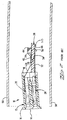
- FIGURE 4 is a perspective view of the connector of the present invention prior to mounting to a circuit board.
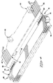
- FIGURE 5 is a cross-sectional view of the edge connector of the present invention exploded from a circuit board.
- FIGURE 6 is a cross-sectional view of the connector of Figure 4 mounted to the circuit board with the card covers exploded therefrom.
- FIGURE 7 is a cross-sectional view of the connector and board of Figure 6 with the card covers attached thereto.
- edge connector will be shown as part of a memory card assembly.
- memory cards is to be understood to include PCMCIA and similar style cards. It is to be understood that the board edge connector of the present invention is not limited to such assemblies.
- Electrical connector 10 includes a housing 12 having a mating face 14 and a board engaging face 18.
- Connector 10 includes a plurality of first terminal members 20 having first contact sections or leads 24 extending from the board engaging face 18 of the housing 12 and a plurality of second terminal members 28 having second contact sections or leads 32 extending rearwardly from the board engaging face 18.
- the first and second contact sections 24,32 define a board receiving entrance 36 therebetween.
- Connector 10 is adapted to be mounted to circuit board 38 having opposed major surfaces 40 and 46 and a corresponding plurality of first and second of circuits or circuit pads 42,48 on opposed major surfaces 40,46 thereof, proximate the leading edge 52, as best seen in Figure 1.
- Circuit board 38 further includes a plurality of large components 44 mounted on the first major surface 40 and a plurality of smaller components 50 mounted on the lower surface thereof.
- contact surface 26 of first contact section 24 engages a corresponding conductor 42 on the first major surface 40 of the board and the contact surface 34 of the second contact section or lead 32 engages a corresponding conductor 48 on the second major surface 46 of the board 38.
- the contact surfaces 26,34 are mechanically and electrically secured to the respective circuits 42,48 by means of solder (not shown), thus securing connector 10 to the board.
- solder not shown
- the unequal forces on opposite sides 40,46 of the board 38 cause the connector housing to rotate with the result that connector 10 is not parallel to the circuit board 38.
- soldering takes place the connector 10 is secured in the nonaligned position.
- Figure 3 illustrates the use of the prior art edge or straddle connector 10 in a memory card or the like.
- the covers of a card frame are typically 0.010 inches thick.
- the connector 10 and circuit board 38 are inserted between the covers 56,58, the circuit board 38 is held in position by supports (not shown) within the covers.
- the connector however, being soldered in the rotated position remains out of alignment with the board.
- the bottom cover 58 being thin will follow the shape of the connector and resile sufficiently to maintain contact with the lower edge of the connector.
- top cover 56 on the other hand unless subjected to force will have a tendency to remain straight and will extend and may not be even with the flange or lip 16 at the mating face 14 of the housing 12.
- forcing connector 10 into alignment with the board 38 after the contact surfaces 26,34 have been soldered to the corresponding circuits 42,48 on board 38 places stress on the soldered connections and may in fact break or fracture the soldered connections rendering the memory card inoperable.
- the memory card is designed to be received in a card holder (not shown) having a complementary mating connector.
- the card holder includes a slot of a controlled thickness into which the card must fit. If a card, having a protruding cover that is high enough to interfere with the card holder slot, is inserted into the holder, the card may be forced into misalignment with the connector in the card holder. This could cause damage to the mating terminal members or cause the card cover to peel back and permanently damage the card.
- Connector 60 includes a housing 12 having a mating face 14 and a board engaging face 18.
- Connector 60 includes a plurality of first terminal members 64 having a row 66 of first contact sections or leads 68 extending from the board engaging face 18 and a plurality of second terminal members 74 having a second row 76 of second contact sections or leads 78 extending rearwardly from the board engaging face 18.
- the connector 60 is designed to be mounted to a circuit board 38 having the same construction as previously described.
- FIGS. 5 and 6 respectively, illustrate connector 60 prior to and after being mounted to the circuit board 38.
- Each of the first row contact sections 68 includes a contact surface 70 which engages the first major surface 40 of the circuit board 38 at 43.
- First position 43 is a selected distance from the leading edge 52 of the board 38.
- Each of the second contact sections 78 engage the second major board surface 46 at second and third positions 53,54 respectively.
- the second position 53 is at least proximate the leading edge 52 of the board 38 and the third position 54 is farther from the board edge 52 than the first position 43.
- the second and third positions 53,54 are thereby axially offset from each other and from the first position 43 and engage the board 38 under spring bias at respective positions 53,54 staggered from the first position 43.
- the arrangement altogether defines a stable board support having minimum rotation.
- Figure 7 illustrates the alignment of the connector 60 and board 38 when used in assembling it a memory card having respective covers 56 and 58.
- top cover 56 is aligned with the flange 16 at the mating face 14 of the connector 60 and the lower cover 58 is aligned with the flange 16 extending from the lower edge of connector 60.
- the result and card assembly presents no protruding edges or gaps as shown with respect to prior art connector 10 in Figure 3 and thus presents no problems when being mated with the complementary connector (not shown). Since the housing 12 is in parallel alignment with the board 38, no stress is placed on the soldered joints as the memory card is assembled.
- the present invention additionally has the advantage that the connector can support the board in the desired alignment without the need for specialized hold down devices on the connector or through holes in the board all of which would require additional board space.
Abstract
Description
- This invention relates to circuit board connectors and more particularly to board edge connectors having surface mountable terminal members.
- One type of electrical connector used in today's electronic equipment is termed a "board edge" connector or "straddle mount" connector. The edge connector is provided for receiving a circuit board having a mating edge and a plurality of contact pads or conductors exposed adjacent the mating edge of the board. Most often, the terminal members in the connectors include cantilevered spring arms which are in biased engagement against the contact pads on the board. In some applications the board edge connector and the attached circuit board form a subassembly for a further device.
- One such use for edge mount connectors is in the assembly of making memory cards or such devices. In making such cards a connector is mounted to a circuit board having a plurality of electronic components mounted thereto. The position of the board relative to the connector is dependent upon the amount of space needed for the various components mounted on the board. In many of the cards, the board needs to be offset from the center line of the connector to allow room for larger components on one side and smaller components on the other. Typically the terminal members have surface mounted contact leads and they are soldered to the respective circuit pads on the board. To assure proper assembly of the memory card, it is desirable that the electrical connector be parallel to the circuit board to enable the covers to be secured around the assembly and to prevent stress on the soldered terminal members. It is also desirable that the connector be able to support the board in the desired alignment without the need for additional mounting means or for through holes or other devices that require additional space on the circuit board.
- The present invention is directed to alleviate the problems associated with the prior art by providing an improved offset straddle mount or edge connector having a stable board support with a minimal rotation. The board edge electrical connector includes a housing having a plurality of first and second terminal members disposed therein, the terminal members having respective contact sections extending in opposed first and second rows from a board engaging surface of the housing. The rows of contact sections define a board receiving entrance therebetween. Each of the first row contact sections include a contact surface adapted to engage a corresponding circuit of the circuit board at a first position. Each of the second row contact sections are adapted to engage a second major surface of the board at both a second position proximate the board edge and a third position farther from the board edge than the first position with each second contact sections electrically connected at at least one of the positions. The second and third positions are axially offset from each other and from the first position thereby enabling the second row contact to engage the board under spring bias at respective positions staggered from the first position. The arrangement altogether defines a stable board support having minimal rotation.
- The present invention provides an advantage of having three points of support to improve the alignment of the connector with the board. The board being held in alignment with the connector facilitates assembly into further components such as memory cards or the like and also prevents damage of the contacts when the connector is mated to its complementary connector. An embodiment of the invention will now be described by way of example with reference to the accompanying drawings in which:
- FIGURE 1 is a cross-sectional view of a prior art edge connector exploded from a circuit board.
- FIGURE 2 is a cross-sectional view of the prior art connector of Figure 1 mounted to the circuit board with the card covers exploded therefrom.
- FIGURE 3 is a cross-sectional view of the connector and board of Figure 2 having card covers attached thereto and illustrating the problem associated with the prior art.
- FIGURE 4 is a perspective view of the connector of the present invention prior to mounting to a circuit board.
- FIGURE 5 is a cross-sectional view of the edge connector of the present invention exploded from a circuit board.
- FIGURE 6 is a cross-sectional view of the connector of Figure 4 mounted to the circuit board with the card covers exploded therefrom.
- FIGURE 7 is a cross-sectional view of the connector and board of Figure 6 with the card covers attached thereto.
- For purposes of illustration of the invention the edge connector will be shown as part of a memory card assembly. For purposes of this invention the term memory cards is to be understood to include PCMCIA and similar style cards. It is to be understood that the board edge connector of the present invention is not limited to such assemblies.
- Figures 1, 2 and 3 illustrate the prior art connector and the problems associated therewith.
Electrical connector 10 includes ahousing 12 having amating face 14 and aboard engaging face 18.Connector 10 includes a plurality of firstterminal members 20 having first contact sections or leads 24 extending from theboard engaging face 18 of thehousing 12 and a plurality ofsecond terminal members 28 having second contact sections or leads 32 extending rearwardly from theboard engaging face 18. The first andsecond contact sections board receiving entrance 36 therebetween. -
Connector 10 is adapted to be mounted tocircuit board 38 having opposedmajor surfaces circuit pads major surfaces edge 52, as best seen in Figure 1.Circuit board 38 further includes a plurality oflarge components 44 mounted on the firstmajor surface 40 and a plurality ofsmaller components 50 mounted on the lower surface thereof. As seen in Figure 2, upon mountingprior art connector 10 to thecircuit board 38contact surface 26 offirst contact section 24 engages acorresponding conductor 42 on the firstmajor surface 40 of the board and thecontact surface 34 of the second contact section orlead 32 engages acorresponding conductor 48 on the secondmajor surface 46 of theboard 38. After assembling theconnector 10 to theboard 38 as shown in Figure 2, thecontact surfaces respective circuits connector 10 to the board. In the asymmetrical arrangement ofcard 38 with respect to thehousing 12, as shown in Figure 2, the unequal forces onopposite sides board 38 cause the connector housing to rotate with the result thatconnector 10 is not parallel to thecircuit board 38. When soldering takes place theconnector 10 is secured in the nonaligned position. - Figure 3 illustrates the use of the prior art edge or
straddle connector 10 in a memory card or the like. The covers of a card frame are typically 0.010 inches thick. When theconnector 10 andcircuit board 38 are inserted between thecovers circuit board 38 is held in position by supports (not shown) within the covers. The connector, however, being soldered in the rotated position remains out of alignment with the board. In assembling the "nonaligned" edge connector and board assembly into a memory card frame, thebottom cover 58 being thin will follow the shape of the connector and resile sufficiently to maintain contact with the lower edge of the connector. Thetop cover 56, on the other hand unless subjected to force will have a tendency to remain straight and will extend and may not be even with the flange orlip 16 at themating face 14 of thehousing 12. As can be seen from Figure 3, forcingconnector 10 into alignment with theboard 38 after thecontact surfaces corresponding circuits board 38 places stress on the soldered connections and may in fact break or fracture the soldered connections rendering the memory card inoperable. - The memory card is designed to be received in a card holder (not shown) having a complementary mating connector. The card holder includes a slot of a controlled thickness into which the card must fit. If a card, having a protruding cover that is high enough to interfere with the card holder slot, is inserted into the holder, the card may be forced into misalignment with the connector in the card holder. This could cause damage to the mating terminal members or cause the card cover to peel back and permanently damage the card.
- The improved edge mount connector of the present invention is illustrated in Figures 4 through 7. For purposes of illustrating the invention the
same housing 12 and corresponding numbers have been used as in the previous discussion.Connector 60 includes ahousing 12 having amating face 14 and aboard engaging face 18.Connector 60 includes a plurality of firstterminal members 64 having arow 66 of first contact sections or leads 68 extending from theboard engaging face 18 and a plurality ofsecond terminal members 74 having asecond row 76 of second contact sections or leads 78 extending rearwardly from theboard engaging face 18. Theconnector 60 is designed to be mounted to acircuit board 38 having the same construction as previously described. - Figures 5 and 6 respectively, illustrate
connector 60 prior to and after being mounted to thecircuit board 38. Each of the firstrow contact sections 68 includes acontact surface 70 which engages the firstmajor surface 40 of thecircuit board 38 at 43.First position 43 is a selected distance from the leadingedge 52 of theboard 38. Each of thesecond contact sections 78 engage the secondmajor board surface 46 at second andthird positions second position 53 is at least proximate the leadingedge 52 of theboard 38 and thethird position 54 is farther from theboard edge 52 than thefirst position 43. The second andthird positions first position 43 and engage theboard 38 under spring bias atrespective positions first position 43. The arrangement altogether defines a stable board support having minimum rotation. - Figure 7 illustrates the alignment of the
connector 60 andboard 38 when used in assembling it a memory card havingrespective covers top cover 56 is aligned with theflange 16 at themating face 14 of theconnector 60 and thelower cover 58 is aligned with theflange 16 extending from the lower edge ofconnector 60. The result and card assembly presents no protruding edges or gaps as shown with respect toprior art connector 10 in Figure 3 and thus presents no problems when being mated with the complementary connector (not shown). Since thehousing 12 is in parallel alignment with theboard 38, no stress is placed on the soldered joints as the memory card is assembled. - The present invention additionally has the advantage that the connector can support the board in the desired alignment without the need for specialized hold down devices on the connector or through holes in the board all of which would require additional board space.
Claims (4)
- An electrical connector (60) including a housing (12) having a plurality of first and second terminal members (64,74) disposed therein, each of said first and second terminal members (64,74) having a respective contact section (68,78) extending in corresponding first and second rows (66,76) from a board engaging face (18) and defining a board receiving entrance (84) therebetween;each of said first row contact sections (68) including a respective contact surface (70) adapted to engage a corresponding circuit at a first position (43) on a first major surface (40) of a circuit board (38), said first position (43) being a selected distance from an edge (52) of said board (38); the connector being characterized in that:each of said second row contact sections (78) are adapted to engage a second major surface (46) of said circuit board (38) only at spaced apart second and third positions (51,53) from said edge (52) of said board (38), said second position (51) being at least proximate to said board edge (52) and said third position (53) being farther from said board edge (52) than said first position (43), each of said second row contact sections (78) including a contact surface (82) adapted to engage a corresponding circuit on said second board surface (46) at at least one of said second and third positions (51,53);whereby said second and third positions (51,53)are axially offset from each other and from said first position (43) enabling said second row contact sections (78) to engage said board (38) under spring bias at respective positions staggered from said first position (43) and the arrangement altogether defining a stable board support with minimal rotation.
- The electrical connector (60) of claim 1 wherein leading ends of said first and second contact sections (68,78) diverge at said board receiving entrance (84) .
- The electrical connector (60) of claim 1 wherein each of said second contact sections (78) has a sharply defined bend (82) which engages said board (38) at said third position (53).
- The electrical connector (60) of claim 1 wherein each of said first contact sections (68) are laterally offset from a corresponding body portion of the respective said first terminal member (64).
Applications Claiming Priority (2)
| Application Number | Priority Date | Filing Date | Title |
|---|---|---|---|
| US08/332,164 US5472349A (en) | 1994-10-31 | 1994-10-31 | Surface mountable board edge connector |
| US332164 | 1994-10-31 |
Publications (2)
| Publication Number | Publication Date |
|---|---|
| EP0709931A2 true EP0709931A2 (en) | 1996-05-01 |
| EP0709931A3 EP0709931A3 (en) | 1997-01-02 |
Family
ID=23297000
Family Applications (1)
| Application Number | Title | Priority Date | Filing Date |
|---|---|---|---|
| EP95307451A Ceased EP0709931A3 (en) | 1994-10-31 | 1995-10-19 | Surface mountable board edge connector |
Country Status (4)
| Country | Link |
|---|---|
| US (1) | US5472349A (en) |
| EP (1) | EP0709931A3 (en) |
| JP (1) | JPH08213119A (en) |
| TW (1) | TW277174B (en) |
Cited By (1)
| Publication number | Priority date | Publication date | Assignee | Title |
|---|---|---|---|---|
| DE102005007931A1 (en) * | 2005-02-10 | 2006-08-24 | Valeo Schalter Und Sensoren Gmbh | Pluggable connector e.g. for motor vehicle electronic system, includes spring contact part with contact section for contacting circuit-board contact |
Families Citing this family (20)
| Publication number | Priority date | Publication date | Assignee | Title |
|---|---|---|---|---|
| WO1995020250A1 (en) * | 1994-01-25 | 1995-07-27 | North American Specialties Corporation | Smart card connector |
| JP3279443B2 (en) * | 1994-09-08 | 2002-04-30 | ミツミ電機株式会社 | Data recording / reproducing device |
| JPH1055864A (en) * | 1996-08-09 | 1998-02-24 | Amp Japan Ltd | Board fitting terminal assembly and board assembly using it |
| US6089882A (en) * | 1996-11-27 | 2000-07-18 | The Whitaker Corporation | Memory card connector with grounding clip |
| AU7876298A (en) * | 1996-12-20 | 1998-07-17 | Whitaker Corporation, The | Memory card connector assembly |
| JP3379882B2 (en) * | 1997-02-18 | 2003-02-24 | 本多通信工業株式会社 | Connector and its surface mounting method |
| US6315620B1 (en) | 1997-04-24 | 2001-11-13 | Seagate Technology Llc | System, method, and device for a pre-loaded straddle mounted connector assembly |
| US6287977B1 (en) | 1998-07-31 | 2001-09-11 | Applied Materials, Inc. | Method and apparatus for forming improved metal interconnects |
| US6120323A (en) * | 1999-07-20 | 2000-09-19 | Hon Hai Precision Ind. Co., Ltd. | Electrical connector |
| US7014475B1 (en) * | 2004-11-10 | 2006-03-21 | Samtec, Inc. | Edge mount electrical connector |
| JP2006139528A (en) * | 2004-11-12 | 2006-06-01 | Mitsuba Corp | Branch unit for sequencer |
| CN100578861C (en) * | 2005-05-31 | 2010-01-06 | 华硕电脑股份有限公司 | Structure of narrow boards |
| JP4832109B2 (en) * | 2006-02-27 | 2011-12-07 | 矢崎総業株式会社 | Electrical junction box |
| JP2009199743A (en) * | 2008-02-19 | 2009-09-03 | Japan Aviation Electronics Industry Ltd | Electrical connector |
| US8277232B2 (en) | 2010-10-07 | 2012-10-02 | Tyco Electronics Corporation | Straddle mount connector |
| US8123534B1 (en) | 2010-10-07 | 2012-02-28 | Tyco Electronics Corporation | Mounting features for straddle mount connectors |
| DE202012002352U1 (en) * | 2011-05-17 | 2012-04-18 | Erni Electronics Gmbh | Arrangement of plug connector and circuit board |
| DE102011076988A1 (en) * | 2011-06-06 | 2012-12-06 | Robert Bosch Gmbh | Direct plug-in element with protected direct contact |
| US8777635B1 (en) * | 2012-12-21 | 2014-07-15 | Tyco Electronics Corporation | Daughter card assembly having a power contact |
| US20150099398A1 (en) * | 2013-10-07 | 2015-04-09 | Eli Benoliel | Connector for printed circuit boards |
Family Cites Families (24)
| Publication number | Priority date | Publication date | Assignee | Title |
|---|---|---|---|---|
| NL133824C (en) * | 1960-06-03 | |||
| US3215968A (en) * | 1960-12-21 | 1965-11-02 | Adolf L Herrmann | Printed circuit board connector |
| US3160455A (en) * | 1961-05-16 | 1964-12-08 | Burroughs Corp | Printed circuit boards and connectors therefor |
| US3173732A (en) * | 1962-02-09 | 1965-03-16 | Brown Engineering Company Inc | Printed circuit board connector |
| GB1147037A (en) * | 1966-08-06 | 1969-04-02 | Ibm | Connector assembly |
| US3783433A (en) * | 1971-01-18 | 1974-01-01 | Litton Systems Inc | Solderless electrical connection system |
| US3725853A (en) * | 1971-03-22 | 1973-04-03 | Bendix Corp | Electrical contact |
| US3858961A (en) * | 1973-06-06 | 1975-01-07 | Itt | Printed circuit board connector |
| US3993383A (en) * | 1975-06-02 | 1976-11-23 | Vincent Marino | Printed circuit electrical connectors |
| US4298237A (en) * | 1979-12-20 | 1981-11-03 | Bell Telephone Laboratories, Incorporated | Printed wiring board interconnection apparatus |
| US4303291A (en) * | 1980-11-24 | 1981-12-01 | Western Electric Company, Inc. | Method of seating connector terminals on circuit board contact pads |
| US4577922A (en) * | 1985-04-04 | 1986-03-25 | Molex Incorporated | Laminated electrical connector arrangement |
| BR8701399A (en) * | 1986-04-03 | 1988-01-05 | Du Pont | CONTACT STRIP AND PROCESS FOR THE PRODUCTION OF A ROW OF EDGE CLAMP CONNECTORS, OR OF A SINGLE EDGE CLAMP CONNECTOR |
| FR2625040B1 (en) * | 1987-12-22 | 1991-01-04 | Cit Alcatel | CONNECTION DELAY PLOT FOR FIXING A CLAW SPINDLE ON THE WAFER OF A HYBRID CIRCUIT SUBSTRATE |
| ATE124812T1 (en) * | 1989-04-17 | 1995-07-15 | Connector Systems Tech Nv | MODULAR CONNECTOR SYSTEM WITH SURFACE MOUNTED CONNECTORS HIGH CONTACT ELEMENT DENSITY. |
| FR2647971B1 (en) * | 1989-06-01 | 1991-09-20 | Itt Composants Instr | CONNECTION ASSEMBLY FOR PRINTED CIRCUIT BOARDS |
| US4998886A (en) * | 1989-07-07 | 1991-03-12 | Teledyne Kinetics | High density stacking connector |
| US5024609A (en) * | 1990-04-04 | 1991-06-18 | Burndy Corporation | High-density bi-level card edge connector and method of making the same |
| US5141445A (en) * | 1991-04-30 | 1992-08-25 | Thomas & Betts Corporation | Surface mounted electrical connector |
| US5342208A (en) * | 1992-02-19 | 1994-08-30 | Nec Corporation | Package connector apparatus |
| US5203725A (en) * | 1992-03-16 | 1993-04-20 | Molex Incorporated | Biased edge card connector |
| US5197887A (en) * | 1992-03-27 | 1993-03-30 | International Business Machines Corporation | High density circuit connector |
| US5259767A (en) * | 1992-07-10 | 1993-11-09 | Teledyne Kinetics | Connector for a plated or soldered hole |
| US5239748A (en) * | 1992-07-24 | 1993-08-31 | Micro Control Company | Method of making high density connector for burn-in boards |
-
1994
- 1994-10-31 US US08/332,164 patent/US5472349A/en not_active Expired - Fee Related
- 1994-11-10 TW TW083110392A patent/TW277174B/zh active
-
1995
- 1995-10-19 EP EP95307451A patent/EP0709931A3/en not_active Ceased
- 1995-10-31 JP JP7306563A patent/JPH08213119A/en active Pending
Non-Patent Citations (1)
| Title |
|---|
| None |
Cited By (2)
| Publication number | Priority date | Publication date | Assignee | Title |
|---|---|---|---|---|
| DE102005007931A1 (en) * | 2005-02-10 | 2006-08-24 | Valeo Schalter Und Sensoren Gmbh | Pluggable connector e.g. for motor vehicle electronic system, includes spring contact part with contact section for contacting circuit-board contact |
| DE102005007931B4 (en) * | 2005-02-10 | 2008-01-10 | Valeo Schalter Und Sensoren Gmbh | Connector and electronic component |
Also Published As
| Publication number | Publication date |
|---|---|
| TW277174B (en) | 1996-06-01 |
| EP0709931A3 (en) | 1997-01-02 |
| US5472349A (en) | 1995-12-05 |
| JPH08213119A (en) | 1996-08-20 |
Similar Documents
| Publication | Publication Date | Title |
|---|---|---|
| US5472349A (en) | Surface mountable board edge connector | |
| US5496180A (en) | Surface mountable card edge connector | |
| JP3066940B2 (en) | Electrical connector for card reader | |
| US4264114A (en) | Electrical connector assembly | |
| US5046955A (en) | Active connector assembly | |
| US5906496A (en) | Miniature card edge clip | |
| US6315620B1 (en) | System, method, and device for a pre-loaded straddle mounted connector assembly | |
| EP1058352B1 (en) | Electrical connector | |
| US5769645A (en) | Electrical connector for dual printed circuit boards | |
| EP0403370A1 (en) | Multi-row box connector | |
| US5911597A (en) | Connector for flexible conductive line components | |
| US5613860A (en) | Universal grounding clip for card-receiving connector | |
| US6109952A (en) | Terminal connector assembly | |
| EP0413008A1 (en) | Insertable latch means for use in an electrical connector. | |
| US5704807A (en) | Surface mountable retention bracket for electrical connectors | |
| JPH09505435A (en) | Right angle electrical connector and member for inserting it | |
| WO1998024154A1 (en) | Memory card connector with grounding clip | |
| US5755592A (en) | Combined ground strap and board lock for electrical connector assembly | |
| KR20050013586A (en) | Electrical connector with wire management module | |
| US5135412A (en) | Hold-down terminal | |
| KR960706701A (en) | CONNECTOR FOR HIGH DENSITY ELECTRONIC ASSEMBLIES | |
| US5009611A (en) | High density electrical connector for printed circuit boards | |
| US6036506A (en) | Right angle electrical connector | |
| EP0766854B1 (en) | Sim card connector | |
| EP0724312B1 (en) | Multiposition electrical connector filter adapter |
Legal Events
| Date | Code | Title | Description |
|---|---|---|---|
| PUAI | Public reference made under article 153(3) epc to a published international application that has entered the european phase |
Free format text: ORIGINAL CODE: 0009012 |
|
| AK | Designated contracting states |
Kind code of ref document: A2 Designated state(s): DE GB IE |
|
| PUAL | Search report despatched |
Free format text: ORIGINAL CODE: 0009013 |
|
| AK | Designated contracting states |
Kind code of ref document: A3 Designated state(s): DE GB IE |
|
| 17P | Request for examination filed |
Effective date: 19970627 |
|
| GRAG | Despatch of communication of intention to grant |
Free format text: ORIGINAL CODE: EPIDOS AGRA |
|
| 17Q | First examination report despatched |
Effective date: 19990414 |
|
| STAA | Information on the status of an ep patent application or granted ep patent |
Free format text: STATUS: THE APPLICATION HAS BEEN REFUSED |
|
| 18R | Application refused |
Effective date: 19991004 |