EP0497529B1 - Apparatus for connecting adjustable reach steering column to impact actuated means - Google Patents
Apparatus for connecting adjustable reach steering column to impact actuated means Download PDFInfo
- Publication number
- EP0497529B1 EP0497529B1 EP92300667A EP92300667A EP0497529B1 EP 0497529 B1 EP0497529 B1 EP 0497529B1 EP 92300667 A EP92300667 A EP 92300667A EP 92300667 A EP92300667 A EP 92300667A EP 0497529 B1 EP0497529 B1 EP 0497529B1
- Authority
- EP
- European Patent Office
- Prior art keywords
- steering column
- legs
- serrations
- impact
- leg
- Prior art date
- Legal status (The legal status is an assumption and is not a legal conclusion. Google has not performed a legal analysis and makes no representation as to the accuracy of the status listed.)
- Expired - Lifetime
Links
Images

Classifications
-
- B—PERFORMING OPERATIONS; TRANSPORTING
- B62—LAND VEHICLES FOR TRAVELLING OTHERWISE THAN ON RAILS
- B62D—MOTOR VEHICLES; TRAILERS
- B62D1/00—Steering controls, i.e. means for initiating a change of direction of the vehicle
- B62D1/02—Steering controls, i.e. means for initiating a change of direction of the vehicle vehicle-mounted
- B62D1/16—Steering columns
- B62D1/18—Steering columns yieldable or adjustable, e.g. tiltable
- B62D1/19—Steering columns yieldable or adjustable, e.g. tiltable incorporating energy-absorbing arrangements, e.g. by being yieldable or collapsible
- B62D1/197—Steering columns yieldable or adjustable, e.g. tiltable incorporating energy-absorbing arrangements, e.g. by being yieldable or collapsible incorporating devices for preventing ingress of the steering column into the passengers space in case of accident
-
- B—PERFORMING OPERATIONS; TRANSPORTING
- B62—LAND VEHICLES FOR TRAVELLING OTHERWISE THAN ON RAILS
- B62D—MOTOR VEHICLES; TRAILERS
- B62D1/00—Steering controls, i.e. means for initiating a change of direction of the vehicle
- B62D1/02—Steering controls, i.e. means for initiating a change of direction of the vehicle vehicle-mounted
- B62D1/16—Steering columns
- B62D1/18—Steering columns yieldable or adjustable, e.g. tiltable
- B62D1/184—Mechanisms for locking columns at selected positions
Definitions
- This invention relates to an apparatus for connecting an adjustable reach steering column to means for moving, in use, the steering column away from a driver in the event of an impact of the vehicle in which the steering column is mounted.
- a means which is designed to pull a steering wheel column away from the driver in the event of an impact of the vehicle, the means acting in such a manner to pull the steering wheel to one side of the driver.
- DE-A-3 642 437 discloses an apparatus for connecting an adjustable reach steering column to means which moves the steering column away from the driver in the event of vehicle impact.
- the apparatus has a part for connection to the steering column to allow axial adjustment and another part for connection to the means for moving the steering column away from the driver.
- the apparatus incorporates a locking device which acts to prevent relative axial movement between the steering column and the first part upon actuation of said means upon vehicle impact, thereby to allow said means to act as intended on the steering column.
- an apparatus for connecting an adjustable reach steering column to means for moving, in use, the steering column away from a driver in the event of an impact of the vehicle in which the steering column is mounted having a first part for connection to the steering column in such manner as to allow axial adjustment of the steering column relative to said first part and a second part for connection to said means, and the two parts incorporating a locking device which acts to prevent relative axial movement between the steering column and said first part upon actuation of said means upon vehicle impact thereby to allow said means to act as intended on the steering column; characterised in that said first part and said second part are in the form of two flat legs, each leg having serrations along at least part of the length of one edge thereof and ramp portions along the opposite edge, the legs being so arranged that, when one of the legs is inverted relatively to the other, the two parts mate together by means of their ramps in the event of said impact.
- a shear element can be provided interconnecting the two legs to keep them normally in a nesting relationship with one another.
- the serrated block assembly is of such dimensions that its serrations and the serrations on the two legs do not normally interfere with one another, i.e. there is a small clearance between them.
- the block assembly is fixed so that, upon vehicle impact, the second part is pulled by said means and this causes the shear element to shear, thereby allowing the ramps of the leg of the first part to ride up over the ramps of the leg of the second part thereby to engage the serrations of the two legs with the serrations of the block assembly.
- the first and second parts, along with the steering column to which the first part is connected, is caused to be pulled by said means.
- a vehicle steering column 1 incorporates a device 2 which allows the steering column to be manually adjustable by the driver in terms of reach to obtain the most comfortable position of the steering wheel for the driver concerned.
- This adjustable reach apparatus is known and will not be described further.
- the apparatus according to the present invention incorporates a first part which is anchored to the steering column assembly and, in the embodiment illustrated, is anchored to a lock handle bolt 4 of a lock handle 5 and a second part which is anchored to the pulling cable 3.
- the apparatus comprises two legs 6 and 7 which are substantially identical. Each leg has along one edge a series of ramps 6A, 7A, respectively. The opposite edges of each leg have serrated portions 6B and 7B, respectively. As shown in Figure 4, when one leg is inverted relatively to the other, the two legs will mate with the ramps 6A nesting in valleys defined by the ramps. The two legs are held together in nesting relationship by a shear element 8 welded or otherwise secured to the legs. The legs are located by two guide rails 9 in a serrated block assembly 10 with its serrations 10A lying closely adjacent but normally clear of the serrations 6B and 7B along part of the length of the serrations on the legs 6 and 7.
- the serrated block assembly 10 is fixed in a bracket 11 which is welded or otherwise joined to an outer tube 12 forming part of the steering column itself.
- the tube 12, bracket 11 and the block assembly 10 is normally allowed to be adjustable in a linear direction over some 60 mm and because of the clearance, which is about 0.5 mm either side of the leg serrations 6A and 7B, the assembly of the tube, bracket and block can be adjusted over the legs 6 and 7 as, for example, shown by an alternative position indicated in dashed lines in Figure 4.
- the serrations 10A lie close to some of the serrations 6B and 7B.
- one end of the leg 7 is attached to one end of the crash pull cable 3 and the end of the leg 6 remote from the end of the leg 7 just mentioned is anchored to the lock handle bolt 4.
- the means for moving the steering column away from the driver is activated by sudden pulling on the cable 3.
- the shear element 8 breaks and the leg splines or serrations 6B and 7B lock into the splines or serrations of the serrated block assembly 10. Further pulling effort by the cable 3 continues to pull the whole assembly coupled to the steering column, including the two legs, the block assembly 10, the bracket 11, the tube 12 and the lock handle bolt 4.
Landscapes
- Engineering & Computer Science (AREA)
- Chemical & Material Sciences (AREA)
- Combustion & Propulsion (AREA)
- Transportation (AREA)
- Mechanical Engineering (AREA)
- Steering Controls (AREA)
Description
- This invention relates to an apparatus for connecting an adjustable reach steering column to means for moving, in use, the steering column away from a driver in the event of an impact of the vehicle in which the steering column is mounted.
- A means is known which is designed to pull a steering wheel column away from the driver in the event of an impact of the vehicle, the means acting in such a manner to pull the steering wheel to one side of the driver.
- DE-A-3 642 437 discloses an apparatus for connecting an adjustable reach steering column to means which moves the steering column away from the driver in the event of vehicle impact. The apparatus has a part for connection to the steering column to allow axial adjustment and another part for connection to the means for moving the steering column away from the driver. The apparatus incorporates a locking device which acts to prevent relative axial movement between the steering column and the first part upon actuation of said means upon vehicle impact, thereby to allow said means to act as intended on the steering column.
- According to the present invention, there is provided an apparatus for connecting an adjustable reach steering column to means for moving, in use, the steering column away from a driver in the event of an impact of the vehicle in which the steering column is mounted, the apparatus having a first part for connection to the steering column in such manner as to allow axial adjustment of the steering column relative to said first part and a second part for connection to said means, and the two parts incorporating a locking device which acts to prevent relative axial movement between the steering column and said first part upon actuation of said means upon vehicle impact thereby to allow said means to act as intended on the steering column; characterised in that said first part and said second part are in the form of two flat legs, each leg having serrations along at least part of the length of one edge thereof and ramp portions along the opposite edge, the legs being so arranged that, when one of the legs is inverted relatively to the other, the two parts mate together by means of their ramps in the event of said impact.
- A shear element can be provided interconnecting the two legs to keep them normally in a nesting relationship with one another.
- It is therefore the outer edges of the two legs which are provided with the serrations and the two legs are mounted in a serrated block assembly and located by guide rails. The serrated block assembly is of such dimensions that its serrations and the serrations on the two legs do not normally interfere with one another, i.e. there is a small clearance between them.
- The block assembly is fixed so that, upon vehicle impact, the second part is pulled by said means and this causes the shear element to shear, thereby allowing the ramps of the leg of the first part to ride up over the ramps of the leg of the second part thereby to engage the serrations of the two legs with the serrations of the block assembly. Thus the first and second parts, along with the steering column to which the first part is connected, is caused to be pulled by said means.
- For a better understanding of the invention and to show how the same may be carried into effect, reference will now be made, by way of example, to the accompanying drawings, in which:-
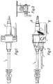
- Figure 1 is a plan view of a vehicle steering column incorporating manually operable means to adjust the reach of the steering column,
- Figure 2 is a side view of the steering column shown in Figure 1 incorporating an apparatus according to the present invention,
- Figure 3 is an end view viewed generally on the line III-III in Figure 2,
- Figure 4 is an enlarged side view of the apparatus according to the invention before activation caused by impact of the vehicle,
- Figure 5 is a diagrammatic sectional view taken on the line V-V in Figure 4, and
- Figure 6 is a view of part of the apparatus shown in Figure 4 after activation caused by vehicle impact.
- Referring to the drawings, a vehicle steering column 1 incorporates a device 2 which allows the steering column to be manually adjustable by the driver in terms of reach to obtain the most comfortable position of the steering wheel for the driver concerned. This adjustable reach apparatus is known and will not be described further.
- Also known is a means to pull the steering wheel away to one side of the driver in the event of an impact of the vehicle. Again, it is not necessary to describe details of this further, save for the fact that part of the means is a
cable 3 which is connected at one end to the steering column 1 and which is pulled by another part of the means in the event of vehicle impact. In Figures 2 and 4, thecable 3 is pulled to the left. - The apparatus according to the present invention incorporates a first part which is anchored to the steering column assembly and, in the embodiment illustrated, is anchored to a
lock handle bolt 4 of alock handle 5 and a second part which is anchored to the pullingcable 3. - In more detail, as best viewed in Figures 4 to 6, the apparatus comprises two
legs ramps serrated portions ramps 6A nesting in valleys defined by the ramps. The two legs are held together in nesting relationship by ashear element 8 welded or otherwise secured to the legs. The legs are located by twoguide rails 9 in aserrated block assembly 10 with itsserrations 10A lying closely adjacent but normally clear of theserrations legs - The
serrated block assembly 10 is fixed in abracket 11 which is welded or otherwise joined to anouter tube 12 forming part of the steering column itself. Thetube 12,bracket 11 and theblock assembly 10 is normally allowed to be adjustable in a linear direction over some 60 mm and because of the clearance, which is about 0.5 mm either side of theleg serrations legs serrations 10A lie close to some of theserrations leg 7 is attached to one end of thecrash pull cable 3 and the end of theleg 6 remote from the end of theleg 7 just mentioned is anchored to thelock handle bolt 4. - Referring to Figure 6, when the vehicle experiences impact, the means for moving the steering column away from the driver is activated by sudden pulling on the
cable 3. Theleg 7, with its ramps which are at about 45°, tries to separate from theleg 6. Theshear element 8 breaks and the leg splines orserrations serrated block assembly 10. Further pulling effort by thecable 3 continues to pull the whole assembly coupled to the steering column, including the two legs, theblock assembly 10, thebracket 11, thetube 12 and thelock handle bolt 4.
Claims (6)
- An apparatus for connecting an adjustable reach steering column (1) to means (3) for moving, in use, the steering column away from a driver in the event of an impact of the vehicle in which the steering column is mounted, the apparatus having a first part (6) for connection to the steering column in such manner as to allow axial adjustment of the steering column relative to said first part and a second part (7) for connection to said means, and the two parts incorporating a locking device (6A,B; 7A,B; 10) which acts to prevent relative axial movement between the steering column and said first part upon actuation of said means (3) upon vehicle impact thereby to allow said means to act as intended on the steering column; characterised in that said first part and said second part are in the form of two flat legs (6, 7), each leg having serrations (6B, 7B) along at least part of the length of one edge thereof and ramp portions (6A, 7A) along the opposite edge, the legs being so arranged that, when one of the legs is inverted relatively to the other, the two parts mate together by means of their ramps in the event of said impact.
- An apparatus according to claim 1, wherein said first and second parts are substantially identical.
- An apparatus according to claim 1 or 2, wherein a shear element (8) is provided interconnecting the two legs to keep them normally in a nesting relationship with one another.
- An apparatus according to claim 1, 2 or 3, wherein the legs are mounted in a serrated block assembly (10) and located by guide rails (9), the serrated block assembly being of such dimensions that its serrations and the serrations on the two legs do not normally interfere with one another.
- An apparatus according to claim 4, wherein the block assembly (10) is fixed so that, upon vehicle impact, the second part (7) is pulled by said means and this causes the shear element (8) to shear, thereby allowing the ramps of the leg of the first part (6) to ride up over the ramps of the leg of the second part, thereby to engage the serrations of the two legs with the serrations of the block assembly.
- A vehicle incorporating apparatus according to any one of the preceding claims.
Applications Claiming Priority (2)
| Application Number | Priority Date | Filing Date | Title |
|---|---|---|---|
| GB9101801 | 1991-01-28 | ||
| GB9101801A GB2252085B (en) | 1991-01-28 | 1991-01-28 | Apparatus for connecting adjustable reach steering column to impact actuating means. |
Publications (3)
| Publication Number | Publication Date |
|---|---|
| EP0497529A2 EP0497529A2 (en) | 1992-08-05 |
| EP0497529A3 EP0497529A3 (en) | 1992-11-19 |
| EP0497529B1 true EP0497529B1 (en) | 1995-03-08 |
Family
ID=10689114
Family Applications (1)
| Application Number | Title | Priority Date | Filing Date |
|---|---|---|---|
| EP92300667A Expired - Lifetime EP0497529B1 (en) | 1991-01-28 | 1992-01-27 | Apparatus for connecting adjustable reach steering column to impact actuated means |
Country Status (5)
| Country | Link |
|---|---|
| US (1) | US5209512A (en) |
| EP (1) | EP0497529B1 (en) |
| DE (1) | DE69201575T2 (en) |
| ES (1) | ES2069375T3 (en) |
| GB (1) | GB2252085B (en) |
Families Citing this family (9)
| Publication number | Priority date | Publication date | Assignee | Title |
|---|---|---|---|---|
| DE4239999A1 (en) * | 1992-11-27 | 1994-06-01 | Bayerische Motoren Werke Ag | Collapsible steering column for protection of driver in collision - is activated by accelerometer which frees spring to allow traction cable to telescope upper and lower sections of column |
| GB2281539A (en) * | 1993-09-01 | 1995-03-08 | Torrington Co | Adjustable vehicle steering column assembly |
| US6167777B1 (en) | 1998-12-14 | 2001-01-02 | Chrysler Corporation | Tiltable steering column lock mechanism |
| ES2157762B1 (en) * | 1999-02-26 | 2002-02-16 | Castellon Melchor Daumal | LONGITUDINAL GUIDANCE CONTROL SYSTEM FOR TELESCOPIC TREES AND / OR ASSEMBLIES WITH COLLAPSE MECHANISMS IN STEERING COLUMNS FOR AUTOMOBILE VEHICLES. |
| US6349611B1 (en) | 2000-03-20 | 2002-02-26 | L & P Property Management Company | Cable operated actuator assembly |
| KR100585885B1 (en) * | 2004-02-10 | 2006-06-08 | 남양공업주식회사 | Steering Gear for Simultaneous Tilt and Telescopic Operation |
| US7422238B2 (en) * | 2005-01-11 | 2008-09-09 | Delphi Technologies, Inc. | Rake design for steering column rake adjustment |
| US7827880B2 (en) * | 2005-03-21 | 2010-11-09 | Gm Global Technology Operations, Inc. | Steering column assembly with a quick release bolt |
| DE102021002297B3 (en) * | 2021-04-30 | 2021-12-09 | Daimler Ag | Vehicle with a steering wheel assembly |
Family Cites Families (5)
| Publication number | Priority date | Publication date | Assignee | Title |
|---|---|---|---|---|
| US3742563A (en) * | 1972-02-24 | 1973-07-03 | C Brown | Apparatus for handling cylindrical members |
| DE3544345C2 (en) * | 1984-12-24 | 1994-03-31 | Volkswagen Ag | Safety steering column for motor vehicles |
| DE3642437C1 (en) * | 1986-12-12 | 1988-03-24 | Audi Ag | Steering column mount |
| DE3822460C1 (en) * | 1988-07-02 | 1990-01-04 | Daimler-Benz Aktiengesellschaft, 7000 Stuttgart, De | |
| US5009120A (en) * | 1990-02-23 | 1991-04-23 | General Motors Corporation | Manual control for adjustable steering column |
-
1991
- 1991-01-28 GB GB9101801A patent/GB2252085B/en not_active Expired - Fee Related
-
1992
- 1992-01-13 US US07/819,698 patent/US5209512A/en not_active Expired - Fee Related
- 1992-01-27 DE DE69201575T patent/DE69201575T2/en not_active Expired - Fee Related
- 1992-01-27 EP EP92300667A patent/EP0497529B1/en not_active Expired - Lifetime
- 1992-01-27 ES ES92300667T patent/ES2069375T3/en not_active Expired - Lifetime
Also Published As
| Publication number | Publication date |
|---|---|
| GB9101801D0 (en) | 1991-03-13 |
| DE69201575D1 (en) | 1995-04-13 |
| EP0497529A2 (en) | 1992-08-05 |
| GB2252085A (en) | 1992-07-29 |
| EP0497529A3 (en) | 1992-11-19 |
| GB2252085B (en) | 1994-10-26 |
| ES2069375T3 (en) | 1995-05-01 |
| US5209512A (en) | 1993-05-11 |
| DE69201575T2 (en) | 1995-11-09 |
Similar Documents
| Publication | Publication Date | Title |
|---|---|---|
| CA1247986A (en) | Absorbing steering column for motor vehicles | |
| US6095012A (en) | Steering column for a motor vehicle | |
| US5286056A (en) | Device for absorbing energy transmitted through a vehicle steering column | |
| US7111859B2 (en) | Moveable side step for a vehicle | |
| US5503431A (en) | Adjustable energy absorbing steering column with adjustment disabled during collision | |
| US5547221A (en) | Energy absorbing member for shock absorbing steering column apparatus | |
| US5356179A (en) | Energy absorbing device for a steering column | |
| US20070013180A1 (en) | Collapsible steering assembly with a stationary reaction surface | |
| US5209512A (en) | Apparatus for connecting adjustable reach steering column to actuating means | |
| US5228359A (en) | Steering column bracket assembly | |
| JPH0575057U (en) | Shock absorption type steering column device | |
| JP2002362341A (en) | Automotive pedal support structure | |
| EP1070641B1 (en) | Height adjusting device for a vehicle seat belt | |
| US5560257A (en) | Separable connecting device for a steering column | |
| US5239889A (en) | Locking mechanism for a vehicle steering column | |
| EP0410377B1 (en) | Adjustable shoulder anchorage | |
| EP0999970B1 (en) | Improvements relating to steering assemblies | |
| EP0474400B1 (en) | Steering column equipped with an energy absorption system | |
| US11866093B2 (en) | Energy absorption strap assembly with customizable control bracket | |
| JPH03275B2 (en) | ||
| US12319339B2 (en) | Customizable energy absorption strap assembly for steering system | |
| GB2260953A (en) | Axially adjustable and retractable vehicle steering columns | |
| KR19980022034A (en) | Seat Mounting Device for Vehicle | |
| EP4619281A1 (en) | Heel airbag for a motor vehicle, and motor vehicle having at least one heel airbag | |
| WO2003035451A1 (en) | Steering column clamping mechanism locking device |
Legal Events
| Date | Code | Title | Description |
|---|---|---|---|
| PUAI | Public reference made under article 153(3) epc to a published international application that has entered the european phase |
Free format text: ORIGINAL CODE: 0009012 |
|
| AK | Designated contracting states |
Kind code of ref document: A2 Designated state(s): DE ES FR IT |
|
| PUAL | Search report despatched |
Free format text: ORIGINAL CODE: 0009013 |
|
| AK | Designated contracting states |
Kind code of ref document: A3 Designated state(s): DE ES FR IT |
|
| 17P | Request for examination filed |
Effective date: 19930109 |
|
| 17Q | First examination report despatched |
Effective date: 19931108 |
|
| GRAA | (expected) grant |
Free format text: ORIGINAL CODE: 0009210 |
|
| AK | Designated contracting states |
Kind code of ref document: B1 Designated state(s): DE ES FR IT |
|
| ITF | It: translation for a ep patent filed | ||
| REF | Corresponds to: |
Ref document number: 69201575 Country of ref document: DE Date of ref document: 19950413 |
|
| REG | Reference to a national code |
Ref country code: ES Ref legal event code: FG2A Ref document number: 2069375 Country of ref document: ES Kind code of ref document: T3 |
|
| ET | Fr: translation filed | ||
| PLBE | No opposition filed within time limit |
Free format text: ORIGINAL CODE: 0009261 |
|
| PG25 | Lapsed in a contracting state [announced via postgrant information from national office to epo] |
Ref country code: ES Free format text: LAPSE BECAUSE OF NON-PAYMENT OF DUE FEES Effective date: 19960129 |
|
| 26N | No opposition filed | ||
| PG25 | Lapsed in a contracting state [announced via postgrant information from national office to epo] |
Ref country code: FR Effective date: 19960930 |
|
| PG25 | Lapsed in a contracting state [announced via postgrant information from national office to epo] |
Ref country code: DE Effective date: 19961001 |
|
| REG | Reference to a national code |
Ref country code: FR Ref legal event code: ST |
|
| REG | Reference to a national code |
Ref country code: ES Ref legal event code: FD2A Effective date: 20020916 |
|
| PG25 | Lapsed in a contracting state [announced via postgrant information from national office to epo] |
Ref country code: IT Free format text: LAPSE BECAUSE OF NON-PAYMENT OF DUE FEES;WARNING: LAPSES OF ITALIAN PATENTS WITH EFFECTIVE DATE BEFORE 2007 MAY HAVE OCCURRED AT ANY TIME BEFORE 2007. THE CORRECT EFFECTIVE DATE MAY BE DIFFERENT FROM THE ONE RECORDED. Effective date: 20050127 |