EP0497413A1 - Subband coding system and a transmitter comprising the coding system - Google Patents
Subband coding system and a transmitter comprising the coding system Download PDFInfo
- Publication number
- EP0497413A1 EP0497413A1 EP92200195A EP92200195A EP0497413A1 EP 0497413 A1 EP0497413 A1 EP 0497413A1 EP 92200195 A EP92200195 A EP 92200195A EP 92200195 A EP92200195 A EP 92200195A EP 0497413 A1 EP0497413 A1 EP 0497413A1
- Authority
- EP
- European Patent Office
- Prior art keywords
- signal
- subband
- subband signal
- samples
- scale factor
- Prior art date
- Legal status (The legal status is an assumption and is not a legal conclusion. Google has not performed a legal analysis and makes no representation as to the accuracy of the status listed.)
- Granted
Links
Images


Classifications
-
- G—PHYSICS
- G10—MUSICAL INSTRUMENTS; ACOUSTICS
- G10L—SPEECH ANALYSIS OR SYNTHESIS; SPEECH RECOGNITION; SPEECH OR VOICE PROCESSING; SPEECH OR AUDIO CODING OR DECODING
- G10L19/00—Speech or audio signals analysis-synthesis techniques for redundancy reduction, e.g. in vocoders; Coding or decoding of speech or audio signals, using source filter models or psychoacoustic analysis
- G10L19/008—Multichannel audio signal coding or decoding using interchannel correlation to reduce redundancy, e.g. joint-stereo, intensity-coding or matrixing
-
- H—ELECTRICITY
- H04—ELECTRIC COMMUNICATION TECHNIQUE
- H04L—TRANSMISSION OF DIGITAL INFORMATION, e.g. TELEGRAPHIC COMMUNICATION
- H04L9/00—Cryptographic mechanisms or cryptographic arrangements for secret or secure communications; Network security protocols
-
- G—PHYSICS
- G06—COMPUTING; CALCULATING OR COUNTING
- G06T—IMAGE DATA PROCESSING OR GENERATION, IN GENERAL
- G06T9/00—Image coding
- G06T9/007—Transform coding, e.g. discrete cosine transform
-
- H—ELECTRICITY
- H04—ELECTRIC COMMUNICATION TECHNIQUE
- H04B—TRANSMISSION
- H04B1/00—Details of transmission systems, not covered by a single one of groups H04B3/00 - H04B13/00; Details of transmission systems not characterised by the medium used for transmission
- H04B1/66—Details of transmission systems, not covered by a single one of groups H04B3/00 - H04B13/00; Details of transmission systems not characterised by the medium used for transmission for reducing bandwidth of signals; for improving efficiency of transmission
- H04B1/667—Details of transmission systems, not covered by a single one of groups H04B3/00 - H04B13/00; Details of transmission systems not characterised by the medium used for transmission for reducing bandwidth of signals; for improving efficiency of transmission using a division in frequency subbands
-
- G—PHYSICS
- G10—MUSICAL INSTRUMENTS; ACOUSTICS
- G10L—SPEECH ANALYSIS OR SYNTHESIS; SPEECH RECOGNITION; SPEECH OR VOICE PROCESSING; SPEECH OR AUDIO CODING OR DECODING
- G10L19/00—Speech or audio signals analysis-synthesis techniques for redundancy reduction, e.g. in vocoders; Coding or decoding of speech or audio signals, using source filter models or psychoacoustic analysis
- G10L19/02—Speech or audio signals analysis-synthesis techniques for redundancy reduction, e.g. in vocoders; Coding or decoding of speech or audio signals, using source filter models or psychoacoustic analysis using spectral analysis, e.g. transform vocoders or subband vocoders
- G10L19/0204—Speech or audio signals analysis-synthesis techniques for redundancy reduction, e.g. in vocoders; Coding or decoding of speech or audio signals, using source filter models or psychoacoustic analysis using spectral analysis, e.g. transform vocoders or subband vocoders using subband decomposition
Definitions
- Prior-art system is disadvantageous in that the coding in the intensity mode does not always lead to a good signal transmission.
- the system according to the invention is characterized in that the system comprises angle determining means arranged for determining a straight line in a plane formed by a fictive co-ordinate system, for each of the subbands for which an intensity mode coding is possible and for corresponding signal blocks in the first and second subband signal components of such a subband, the line traversing the origin of the co-ordinate system and traversing a point cloud of q points in the plane, which points are formed by combining the k th sample from a q-sample signal block in the first subband signal component with the k th sample from the corresponding q-sample signal block in the second subband signal component, where k varies from 1 to q, and, for determining the k th point in the plane, by plotting the k th sample of the first subband signal component along one axis of the co-ordinate system and the k th sample of the second subband signal component along the other axis, and in that for the line it holds that a distance measure which
- the invention is based on the recognition that prior-art intensity code means that corresponding samples l[k], r[k] in a signal block of the first and second subband signal components in a subband are projected on a line traversing the origin of an l-r co-ordinate system at an angle of 45°, in which the points l[k],r[k] in the plane of the co-ordinate system are obtained by plotting the sample l[k] along the l-axis and the corresponding sample r[k] along the r-axis of the co-ordinate system.
- the transmission in the intensity mode actually means that only the length of the projections of the points on the line, calculated from the origin, are transmitted as samples of the composite subband signal.
- the length, calculated from the origin, of the projections of these points on this projection line are now transmitted as samples inclusive of their signs of the composite subband signal. The result of this coding is that a better transmission is realised. On the other hand, this coding means that one of the scale factors may now be negative.
- the scale factors SF l and SF r may be obtained in various ways.
- the scale factors may be derived in known manner from the original subband signal components. Another possibility is that the scale factors are derived from the scale factor SF lr of the composite subband signal.
- the system according to the invention is thereto characterized in that for determining the scale factor belonging to the corresponding signal block of the first subband signal component of which the composite subband signal is composed, the determining means are arranged for multiplying the amplitude of the sample having the largest amplitude by cos ⁇ , and in that for determining the scale factor belonging to the corresponding signal block of the second subband signal component of which the subband signal is composed, the determining means are arranged for multiplying the amplitude of the sample having the largest amplitude by (-sin ⁇ ).
- the system is characterized in that for determining the scale factor belonging to the corresponding signal block of the first subband signal component of which the composite subband signal is composed, the determining means are arranged for calculating the magnitude where S ll is equal to the sum of the squares of the amplitudes of the q samples in the signal block of the first subband signal component, S2 is equal to the sum of the squares of the q samples in the signal block of the composite subband signal, and SF lr is the amplitude of the largest sample in the q-sample signal block in the composite subband signal.
- S ll is equal to the sum of the squares of the amplitudes of the q samples in the signal block of the first subband signal component
- S2 is equal to the sum of the squares of the q samples in the signal block of the composite subband signal
- SF lr is the amplitude of the largest sample in the q-sample signal block in the composite subband signal.
- this system is characterized in that the coefficient is a function of SF l ' / SF l en SF' r / SF r where SF l and SF r are the scale factors belonging to the corresponding signal blocks of the first and second subband signal components respectively, of which the composite subband signal is composed, and SF' l and SF' r are the values of the quantized scale factors SF l and SF r subsequent to dequantization.
- a compensation is made for the quantization errors in one and also in the other scale factor. The compensation is not complete for either scale factor, but a compensation compensating for at least part of the quantization error is now performed in the two channels.
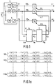
- Fig. 1 shows the coding system.
- a wideband digital signal is applied to the input terminal 1.
- the audio signal may be a stereo audio signal. In that case only one of the two signal components (left or right signal component) of the stereo audio signal will be discussed. The same will happen then with the other signal component.
- 16-bit samples of the left signal component of the audio signal are applied to the input 1 with a sampling frequency of 44 kHz.
- the audio signal is applied to a subband coder 2 which comprises signal splitting means.
- the subband coder 2 splits up the audio signal into M subbands by means of M filters, that is to say, a low-pass filter LP, M-2 band-pass filters BP and a high-pass filter HP.
- M is equal to 32.
- the sampling frequency of the M subband signals is reduced in the blocks referenced 9. The sampling frequency is reduced therein by a factor of M.
- the signals thus obtained are presented at the outputs 3.1, 3.2, ..., 3.M.
- the signal in the lowest subband SB1 is presented at output 3.1.
- the signal in the lowest but one subband SB2 is presented at output 3.2.
- the signal in the highest subband SB M is presented at the output 3.M.
- the signals at the outputs 3.1 to 3.M have the form of successive samples expressed in 16 or over, for example, 24-bit numbers.
- the samples of the left subband signal component appear at the outputs 3.1 to 3.M of Fig. 1. These samples are referenced l[k].
- the subband coding system for the right signal component of the audio signal similarly produces samples r[k] of the right signal component in the subbands SB1 to SB M . This is shown in Fig. 1a.
- the subbands SB1 to SB M have all the same width. This is not necessary, however.
- Prior-art publication (5), Krasner discusses for example, a subdivision into a number of subbands whose bandwidths approximately correspond to the bandwidths of the critical bands of the human auditory system in the respective frequency ranges.
- the subband signals are combined in successive signal blocks of q successive samples, cf . Fig. 1a, and applied to the associated quantizers Q1 to Q M .
- a quantizer Q m the samples are quantized to quantized samples having a number of bits n m smaller than 16.
- Fig. 1 shows how the left subband signals are applied to an associated quantizer Q m in signal blocks of q successive samples which are the samples l[l] to l[q].
- the right subband signals are applied to an associated quantizer (not shown) in signal blocks of q successive samples which are the samples r[l] to r[q].
- q is equal to 12.
- the signal blocks (groups) of q successive samples of the subband signal components are quantized to a smaller number of bits.
- the q samples in a signal block are first normalized. This normalization is effected by dividing the amplitudes of the q samples by the amplitude of the sample having the largest absolute value in the signal block.
- the amplitude of the sample having the largest amplitude in the signal block of the subband SB m provides the scale factor SF m , cf . document (2a), (2b).
- the amplitudes of the normalized samples, which are now situated in an amplitude range from -1 to +1 are quantized.
- the quantized samples in the subbands SB l to SB M are thereafter presented at the respective outputs 4.1 to 4.M.
- the outputs 3.1 to 3.M are further coupled to the respective inputs 5.1 to 5.M of the bit need determining means 6.
- the bit need determining means 6 determine the bit needs b ml and b mr for q-sample signal blocks corresponding with time of the left and right subband signal components in the subbands SB l to SB M .
- the bit needs b ml and b mr are numbers related to the number of bits with which the q samples in a q-sample signal block of the left or right subband signal components respectively, of a signal of the subband m ought to be quantized.
- bit needs b ll to b Ml , and b lr to b Mr derived by the bit need determining means 6 are applied to bit allocation means 7.
- the bit allocation means 7 determine, on the basis of the bit needs, the real number of bits n ll to n Ml and n lr to n Mr with which the q samples of the corresponding signal blocks of the left and right subband signal components in the subband signals SB l to SB M are quantized.
- Control signals corresponding to the numbers n ll to n Ml are applied to the respective quantizers Q l to Q M over the lines 8.1 to 8.M, so that the quantizers are capable of quantizing the samples with the correct numbers of bits.
- control signals corresponding to the numbers n lr to n Mr are applied to associated quantizers (not shown) for the right subband signal components, so that also these quantizers are capable of quantizing the samples of the right subband signal components with the correct numbers of bits.
- the publication (2b) of the reference list describes how in a stereo intensity mode the left and right subband signal components in a subband are combined in one or more subbands, cf . more particularly the description of Fig. 15c in the publication (2b).
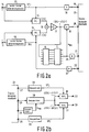
- Fig. 2a shows the structure of this part of the coding system in the publication (2b), which performs a stereo intensity coding of the left and right subband signal components in a subband SB m .
- the input terminal 10 is constantly supplied with q-sample signal blocks of the first subband signal component i.e. the left subband signal component in the subband SB m .
- the input terminal 11 is constantly supplied with q-sample signal blocks of the second subband signal component i.e. the right subband signal component in the subband SB m .
- the left subband signal component referenced l is applied both to a unit 12 and a divider 14. In the unit 12 a scale factor SF l is determined for each signal block in the left subband signal component.
- This scale factor is equal to, for example, the amplitude of the largest sample in the signal block.
- the divider 14 all the samples of the signal block are divided by the scale factor SF l .
- the output of the divider 14 then presents normalized samples referenced l[k] where k varies from 1 to q.
- the samples l[k] are applied to a first input of a signal combining unit 16 formed by an adder.
- the right subband signal component referenced r is applied both to the unit 13 and to a divider 15.
- a scale factor SF r is determined for each signal block in the right subband signal component, which factor is in this case also equal to the amplitude of the largest sample of the signal block.
- the divider 15 In the divider 15 all the samples in the signal block are divided by the scale factor SF r . The output of the divider 15 then presents normalized samples r[k] which are applied to a second input of the signal combining unit 16. Also in this case k varies from 1 to q. In an additional divider 17 the summed samples l[k]+r[k] are divided by 2. The samples thus obtained are applied to the quantizer 18.
- the bit need determining means 6 and the bit allocation means 7 determine, in the manner described, for example, in the documents (9a) and (9b), the number of bits n mc by which the samples in the signal block of the composite subband signal in the subband SB m are to be represented.
- the quantized signal block of the composite subband signal quantized in the quantizer 18 is then applied to the input 20 of a transmission medium 23.
- the scale factors SF l and SF r belonging to the corresponding signal blocks in the left and right subband signal components are applied, after quantization in the quantizers 36 and 37 respectively, to the respective inputs 19 and 22 of the transmission medium 23.
- the allocation information n mc denoting the number of bits by which the samples in the signal block of the quantized composite subband signal are represented, are applied, subsequent to quantization in the quantizer 35, to the input 21 of the transmission medium 23.
- the method described above is constantly repeated for successive corresponding signal blocks in the left and right signal components of the subband SB m .
- the transmission medium 23 may have the form of a wireless transmission such as, for example, a radio transmit channel. However, other transmission mediums are also possible.
- optical transmission for example, through optical fibres or optical record carriers such as compact disc-like media, or a transmission by means of magnetic record carriers utilizing, for example, RDAT or SDAT-like recording or reproducing techniques as described, for example, in document (8) in the reference list.
- the q-sample signal block of the composite subband signal in the subband SB m is derived from the data stream of the quantized samples applied to a dequantizer 29 through the input 26 in response to the allocation information n mc also applied to the dequantizer 29 through the input 25.
- This method is extensively discussed in document (2b) of the reference list.
- the samples thus obtained are then applied to multipliers 30 and 31.
- the scale factor information is also derived from the data stream sent to the receiver via the transmission medium 23. This scale factor information comprises the scale factors SF l and SF r which are also applied to the multipliers 30 and 31 through the inputs 27 and 28 respectively.
- the samples in the signal block of the composite subband signal are multiplied by SF l and SF r in the multipliers 30 and 31 respectively.
- the outputs 32 and 33 then present the left and right subband signal components respectively, in the subband SB m .
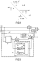
- the samples l[k] and r[k] belonging together in corresponding signal blocks of the left and right subband signal components may be plotted as points in a plane formed by a fictive co-ordinate system, the amplitude l[k] being plotted along one axis of the co-ordinate system and the amplitude r[k] being plotted along the other axis.
- Fig. 3 shows this co-ordinate system.
- P1, P2, P3 and P4 denote four points corresponding to the first four samples that belong together (l[l],r[l]), (l[2],r[2]), (l[3],r[3]) and (l[4],r[4]) in corresponding signal blocks in the left and right signal components of the subband SB m .
- Samples belonging together are added up in the adder 16 to become composite samples l[k]+r[k], divided by two in the divider 17 and transmitted via the transmission medium 23 after being quantized in the quantizer 18.
- the composite samples are applied to both multipliers 30 and 31.
- the samples belonging together and applied to the multipliers 30 and 31 may also be plotted as points in the plane shown in Fig. 3, the amplitude of the sample applied to the multiplier 30 being plotted along the l-axis and the amplitude of the sample applied to the multiplier 31 being plotted along the r-axis. This provides the points P1', P2', P3' and P4'.
- the coding and subsequent decoding does not cause any difficulties. This is due to the fact that the amplitude of the composite sample is relatively large compared to a specific noise level.
- the sample pairs corresponding to the points P3 and P4 are obtained from samples l[k] and r[k] which also have a relatively large amplitude compared to the noise level.
- Fig. 3 shows, however, that the projections of these points on the dashed line lead to composite samples having a relatively small amplitude. This amplitude may be so small as to be of the order of the noise level.
- the multiplication of these composite samples in the multipliers 30 and 31 produces reconstructed samples l r [k] and r r [k] which have a poor signal-to-noise ratio and are thus unreliable.
- the cloud of the q points P k (l[k],r[k]) does not coincide with the line I-I, but is more or less perpendicular to this line.
- projections on the line I-I lead to composite samples having amplitudes which are in most cases very small relative to the amplitudes of the original samples.
- the conclusion of this may be that once the line I-I does not optimally traverse the cloud of points, the coding as described above does not lead to good transmission.
- a coding system is proposed according to the invention, in which a projection is made on a line traversing the cloud of points in the best way possible depending on the position of this cloud of points.
- Fig. 4a shows the situation in which a q-point cloud of points is traversed by the line I-I. The angle ⁇ 1 is thus equal to 45°.
- Fig. 4b shows the situation in which the q-point cloud of points is traversed by the line I'-I' which is at an angle ⁇ 2 relative to the l-axis, which angle is smaller than 45°.
- Fig. 4c shows a q-point cloud of points which is optimally traversed by the line I''-I''.
- the angle ⁇ 3 is about 135°.
- Fig. 5 shows a cloud of points from one of the Figs. 4a, 4b and 4c after transformation to the I-E co-ordinate system according to the above rotation transformation.
- the l-axis after rotation coincides with the I-axis and the r-axis coincides after rotation with the E-axis.
- the transformation of the cloud of points in Fig. 4a to the cloud of points in Fig. 5 means a rotation through an angle ⁇ equal to - ⁇ 1.
- the transformation of the cloud of points in Fig. 4b to Fig. 5 means a rotation through an angle ⁇ equal to - ⁇ 2.
- the transformation of the cloud of points of Fig. 4c to Fig. 5 means a rotation through an angle ⁇ equal to - ⁇ 3.
- the coding at the transmitter end which was based according to the known method on the projection of the points (l,[k],r[k]) on the line I-I in the l-r co-ordinate system, cf . Fig. 3, is now transformed to a coding in the form of a projection of the points (I[k],E[k]) on the I-axis in the I-E co-ordinate system of Fig. 5.
- the projections of the points (I[k],E[k]) on the I-axis are transmitted via the transmission medium. This means that q samples I[k] in a signal block of the composite subband signal are transmitted.
- the I-axis in Fig. 5 is actually the intensity axis and the E-axis is thus the error axis.
- the angle ⁇ is then selected such that is minimized.
- the corresponding signal blocks of the first and second subband signal components in a subband are encoded in the intensity mode if the values E[k] obtained after rotation are small enough. This actually means that the error in the intensity coding is to be smaller than a specific value. If the error is too large, the signal blocks are not encoded in the intensity mode but the normal coding system as described in the documents (9a) and (9b) is performed separately on the corresponding signal blocks in the subband signal components of a subband. Another possibility is that in that case both E[k] and I[k] are transmitted. Possible decision criterions for switching the stereo intensity mode on or off are to be discussed at some later instant.
- Fig. 6 shows an exemplary embodiment of the system according to the invention which is able to code the subband signal components in a subband in the intensity mode.
- the inputs 10 and 11 are supplied with the samples l[k] and r[k] respectively, of corresponding signal blocks in the subband signal components.
- the samples l[k] and r[k] need not first be divided by the scale factors SF l and SF r respectively as was the case in the system shown in Fig. 2.
- the samples l[k] are applied to a unit 40 and a multiplier 41.
- the samples r[k] are also applied to the unit 40 and to a multiplier 42.
- the unit 40 determines, on the basis of the criterion to be discussed hereinafter, whether the relevant subband can be coded in the intensity mode. If this is the case the unit 40 derives the angle ⁇ from the samples l[l] to l[q] and r[l] to r[q] of the corresponding signal blocks in the fashion described above. Actually, the unit 40 determines the angle ⁇ of the lines I-I, I'-I' and I''-I'' in Fig. 4. Within a certain quantization accuracy range ⁇ is then equal to - ⁇ . For the lines located in the first and third quadrants of the l-r co-ordinate system shown in Fig. 4, such as the lines I-I and I'-I' in Figs.
- the unit 40 presents the value for ⁇ at an output for the value ⁇ to be applied to the multipliers 41 and 42.
- the multiplier 41 the samples l[l] to l[q] are multiplied by cos ⁇ and in the multiplier 42 the samples r[l] to r[q] are multiplied by - sin ⁇ .
- Outputs of the multipliers 41 and 42 are coupled to corresponding inputs of the adder 16.
- I[k] l[k]cos ⁇ -r[k]sin ⁇
- the multipliers 45 and 46 multiply the scale factor SF lr by cos ⁇ and -sin ⁇ respectively.
- the respective scale factors SF l and SF r then appear at the outputs of the multipliers 45 and 46.
- the scale factors are quantized in the quantizers 36 and 37 and applied to the transmission medium through the inputs 19 and 22.
- the receiver side in Fig. 6b may in fact be identical with the receiver side in Fig. 2b, and thus means no further explanation.
- the scale factor SF lr and the angle ⁇ could be transmitted.
- the scale factors SF l and SF r could then be reconstructed from SF lr and ⁇ . This is diagrammatically shown in Fig. 6c.
- the scale factors SF l and SF r are first derived and then multiplied by the composite samples so as to produce the samples in the left and right signal components.
- the composite samples could first be multiplied by SF lr at the receiver end and the samples thus obtained could be multiplied by cos ⁇ so as to obtain the left signal component, and by -sin ⁇ so as to obtain the right signal component. This is diagrammatically shown in Fig. 6d.
- multipliers 45 and 46 produce the scale factors SF l and SF r belonging to the original subband signal components.
- the coding at the transmitter end is based on the matrix multiplication as represented above.
- Fig. 7 represents the behaviour of cos ⁇ and sin ⁇ in the region between - ⁇ /2 and ⁇ /2 and thus the behaviour of the sign of SF l and SF r .
- SF lr is always a positive number. This means that SF r has a negative value if ⁇ is situated between 0 and ⁇ /2. This is thus valid in the cases where the cloud of points (l[k],r[k]) is located in the second and fourth quadrants of the co-ordinate system shown in Fig. 4c.
- the result of this is that at least one sign bit for one of the scale factors is to be transmitted.
- the format with which the whole data stream is to be transmitted through the transmission medium is then to be taken into consideration.
- the intensity mode can only be used for frequencies over about 1500 Hz. For each subband in this frequency range and for each q-sample signal block in the left and right subband signal components it has to be decided whether this subband is either or not coded in the intensity mode. Two criterions will be discussed.
- the first criterion starts from an E[k] which is small relative to the signal energy in the subband concerned. In that case a subband is coded in the intensity mode if where D is an arbitrary threshold. If this criterion is compared with the situations shown in Fig. 4, it appears that in all the cases that satisfy this criterion, the cloud of points l[k],r[k] has a cigar-like shape. Consequently, after the rotation transformation the magnitudes E[k] are small. In these cases an intensity coding will be permissible. However, if the cloud of points was more circular, an intensity coding would not be permitted.
- masking may be stated from. There may be derived that the power of the error occurring by omitting the samples E[k] for the left channel is produced by the formula and for the right channel by the formula Omission is permitted if the error in the two channels is masked.
- the exemplary embodiment of the system according to the invention means that at least one sign bit for a scale factor is to be transmitted via the transmission medium.
- the exemplary embodiment which will be discussed hereinafter renders transmitting the sign bit redundant, whereas yet a better transmission may be realised than with prior-art system shown in Fig. 2.
- This second exemplary embodiment is based on the system shown in Fig. 6, where an adaptation is realised in the unit 40.
- the section of the system shown in Fig. 6a is located between the inputs 10 and 11 and the adder 16.
- the unit 40 is shown in more detail in Fig. 9 and referenced by the reference numeral 40'.
- the unit 40' comprises a block 50 which determines the angle ⁇ of the projection lines I-I, I'-I' and I''-I'' in the Figs. 4a, 4b and 4c in above manner.
- a detector 52 detects whether ⁇ is situated between 0 and 90°. If this is the case, the detector 52 applies a detection signal to the control signal generator 55.
- a detector 53 in the comparing unit 51 detects whether ⁇ is situated between 90 and 135°. If this is the case, the detector 53 applies a detection signal to the generator 55.
- the detector 54 detects whether ⁇ is situated between -45° and 0°. If this is the case, the detector 54 applies a detection signal to the generator 55.
- the generator 55 produces first, second or third control signals respectively, to be applied to a control signal input of a controllable switch 56.
- the switch 56 In response to the first control signal the switch 56 connects the terminals a and d. This means that a value ⁇ equal to - ⁇ appears at the output of the unit 40', cf. block 57 in the unit 40' where ⁇ is assumed to be equal to - ⁇ .
- the switch 56 In response to the second control signal the switch 56 connects the terminals c and d. Due to the presence of block 58 in the unit 40', which in this case is coupled to the output of the unit 40', a value for a equal to -90° appears at this output.
- Fig. 8 clarifies that this coding produces a better transmission than the coding described for the system shown in Fig. 2.
- the projection on the r-axis shown in Fig. 8 produces a better approximate of the original samples than the projection on the line I-I in Fig. 3.
- the switch 56 In response to the third control signal the switch 56 connects the terminals b and d. Due to the presence of the block 59 in the unit 40', which is in this case coupled to the output of the unit 40', a value for a equal to 0° appears at this output.
- the third control signal characterizes a situation in which the cloud of points l[k],r[k] is essentially located in the parts of the plane shown in Fig. 8 referenced B. Because ⁇ is in this case assumed to be equal to 0°, this means that a coding of the points is performed in the form of a projection on the l-axis and that only these projections are transmitted via the transmission medium as samples of the composite subband signal. This is immediately clear from Fig.
- Fig. 10 shows this measure implemented in the transmitter according to the invention.
- Fig. 10 shows only the relevant transmitter section of the system shown in Fig. 6a.
- the scale factors were determined in the units 45 and 46. These units are omitted in the exemplary embodiment of Fig. 10 and replaced by the units 65 and 66.
- a first input of the unit 65 is coupled to the input terminal 10 through which the unit 65 is supplied with the samples l[l] to l[q] in a signal block.
- a second input is coupled to the output of the divider 43, so that the unit 65 is supplied with the composite samples i[l] to i[q] through this second input.
- Unit 65 is capable of computing the scale factor SF l from these input signals with the aid of above formula.
- a first input of the unit 66 is coupled to the input terminal 11 and a second input is coupled to the output of the divider 43.
- the unit 66 computes the scale factor SF r on the basis of the signals supplied through these inputs.
- This correction is again implemented in Fig. 11 in a system according to the invention such as the one described, for example, in Fig. 6 or 10. However, it should be observed in this respect that this correction may also be used in systems according to the state of the art which are capable of applying an intensity mode coding to the left and right signal components of a subband.
- the samples i[k] at the transmitter end are first to be divided by (l+ ⁇ ).
- the relevant section of the system which is capable of making corrections for the other value of the quantized scale factor SF l is represented in Fig. 11.
- at least one sign bit for one of the scale factors is to be determined as described hereinbefore with reference to Fig. 6a. This sign bit may then be added to the associated scale factors after which transmission may be effected.
- the output of the quantizer 36 is coupled to the input of a dequantizer 70 in which the quantized scale factor SF l is again dequantized.
- the dequantizer thus produces a value SF' l of the quantized scale factor SF l .
- the outputs of the dequantizer 70 and the unit 36 are coupled to inputs of a divider 71 in which a division of SF' l /SF l is performed for obtaining the value l+ ⁇ .
- This value is applied to a divider 72 inserted between the divider 43 and the quantizer 18.
- the samples i[k] are divided by the value l+ ⁇ .
- a compensation is made for the quantizing error resulting from the quantization of the scale factor SF l .
- the power in the left channel remains constant.
- Fig. 12 shows an exemplary embodiment in which the quantization error in SF l as well as the quantization error in SF r are taken into consideration. Therefore, the system shown in Fig. 12 comprises a dequantizer 75, a divider 76 and a divider 77.
- a compromise is reached so that corrections are made at least partly for the quantization errors in the scale factors in both channels.
- This measure is also applicable to aforementioned state-of-the-art systems.
- a still further possibility would be to detect for each signal block of the left signal component and the corresponding signal block of the right subband signal component which of the two signal blocks is louder, and correct the scale factor belonging to the subband signal component which is the louder in accordance with the method shown in Fig. 11.
- correction factor in the unit 77 is a function of the values (l+ ⁇ ) and (l+ ⁇ ), which function may then further be determined by the value of the scale factors and/or the energies of the two signal components.
- Fig. 13 shows the use of the subband coder as described hereinbefore, in a transmitter, more particularly, a transmitter in the form of a recording device for recording the quantized subband signals in one or more tracks on a magnetic record carrier.
- the section referenced 130 is the afore-discussed subband coder presenting the quantized subband signals at the outputs 4.1 to 4.M.
- the output 4.M actually covers two separate outputs at which the quantized subband signal components are presented.
- the q quantized samples of two corresponding signal blocks in the first and second signal components of the subband m can be presented consecutively at the output 4.m.
- the quantized composite subband signal is presented at an output 4.m. Furthermore, two quantized scale factors SF' l and SF' r for each subband are presented at an output of the section 130. Allocation information for each subband is likewise presented at an output of the section 130. For a subband m, for which the first and second subband signal components are processed separately, the allocation information is thus generated for each subband signal component. Thus, for a subband m processed in the intensity mode, only the allocation information is generated for the quantized composite subband signal.
- the section referenced 131 converts all these signals and includes these signals in a second digital signal to be presented at the output 132.
- This second digital signal is constituted by successive frames whose format is extensively discussed in prior-art documents (2a) and (2b). Also the structure of the block 131 is explained in these documents.
- the section referenced 133 renders the second digital signal suitable for recording on a record carrier, for example, a magnetic record carrier 134.
- the unit 133 thereto comprises an 8-to-10 converter. In such a converter 8-bit data words in the serial information stream are converted to 10-bit codewords. Interleaving may also be effected. All this is aimed at making an error correction of the received information possible at the receive end (when the record carrier is reproduced).
- the output signal of block 133 is applied to write means 135 by which the signal is recorded in one or more longitudinal tracks on the record carrier 134.
- the write means 135 thereto comprise one or more write heads 136.
Abstract

Description
- The invention relates to a coding system comprising a subband coder for subband coding of a wideband digital signal, for example, a digital stereo audio signal, constituted by at least first and second signal components which are sampled each with a specific sampling frequency F₈, the subband coder including signal splitting means for generating, in response to the wideband digital signal, a number of M subband signals by means of a sampling frequency reduction, for which purpose the splitting means split up the wideband signal into successive subbands having bad numbers m which augment with frequency, where m = 1 ≦ m ≦ M, and in which each subband signal is constituted by at least first and second subband signal components, the coding system further including quantizing means for quantizing block-by-block the first and second subband signal components in a subband SBm, a quantized subband signal component comprising successive signal blocks, each signal block containing q samples, the q samples in corresponding signal blocks of the first and second quantized subband signal components in the subband SBm being represented by nml, and nm2 bits respectively, and in which in an intensity mode coding for at least one of the subbands the quantizing means are arranged for combining corresponding samples of the first and second subband signal components in the subband so as to obtain a composite signal in the subband, and are arranged for quantizing block-by-block the composite signal in the subband, the quantized composite signal in the subband being constituted by successive signal blocks, each signal block containing q samples where the q samples in a signal block of the quantized composite signal are represented each by nmc bits, the system further including scale factor information determining means for determining information related to a scale factor belonging to each q-sample signal block in the first and second subband signal components of the subbands, to a transmitter comprising the coding system and to a receiver.
- The system of the type mentioned in the opening paragraph is known from Dutch Patent Application No. 90.00.338 (PHN 13.241), cf. document (2b) in the reference list at the back of this Application. With prior-art system it is possible with some subbands to code the first and second subband signal components in the subbands in a so-called intensity mode. In that case the left and right signal components are combined for obtaining a type of mono signal. Such a signal coding is used if the phase difference between the left and right subband signal components is not important, but if the waveform of the mono signal is important indeed. This is especially the case for signals in higher subbands, because the human auditory system is less phase-sensitive to the frequencies in these subbands. By implementing such a coding, a smaller information content for the subband to be transmitted will suffice with a certain coding accuracy, or a larger information content with a greater coding accuracy. On reproduction at the receiver end a stereo effect is realised known by the name of intensity stereo. Only the intensities of the left and right subband signal components differ, having the different values for the scale factors belonging to the first and second subband signal components.
- Prior-art system is disadvantageous in that the coding in the intensity mode does not always lead to a good signal transmission.
- It is an object of the invention to provide a system with which, even in the cases where no good transmission takes place, a good transmission may yet be realised.
- The system according to the invention is characterized in that the system comprises angle determining means arranged for determining a straight line in a plane formed by a fictive co-ordinate system, for each of the subbands for which an intensity mode coding is possible and for corresponding signal blocks in the first and second subband signal components of such a subband, the line traversing the origin of the co-ordinate system and traversing a point cloud of q points in the plane, which points are formed by combining the kth sample from a q-sample signal block in the first subband signal component with the kth sample from the corresponding q-sample signal block in the second subband signal component, where k varies from 1 to q, and, for determining the kth point in the plane, by plotting the kth sample of the first subband signal component along one axis of the co-ordinate system and the kth sample of the second subband signal component along the other axis, and in that for the line it holds that a distance measure which is a measure of the distance from the line to all the q points is minimum, in that the angle determining means are further arranged for determining an angle β in essence equal to the angle formed by the line and the axis of the co-ordinate system along which the samples of the first subband signal component are plotted, in that the angle determining means comprise a comparator for comparing the distance measure with a threshold, in that the comparator is arranged for generating a control signal if the distance measure does not exceed the threshold, and in that the quantizing means are arranged for performing an intensity mode coding of the corresponding signal blocks in the first and second subband signal components of the relevant subband in response to the control signal, and in that the quantizing means to this end comprise signal combining means for multiplying the q samples of the first subband signal component by cos(α), for multiplying the q corresponding samples of the second subband signal component by -sin(α) and for combining subsequent to the multiplication the corresponding samples of the q-sample first and second subband signal components to become the composite subband signal, and in that α has a relation to the angle β.
- The invention is based on the recognition that prior-art intensity code means that corresponding samples l[k], r[k] in a signal block of the first and second subband signal components in a subband are projected on a line traversing the origin of an l-r co-ordinate system at an angle of 45°, in which the points l[k],r[k] in the plane of the co-ordinate system are obtained by plotting the sample l[k] along the l-axis and the corresponding sample r[k] along the r-axis of the co-ordinate system. The transmission in the intensity mode actually means that only the length of the projections of the points on the line, calculated from the origin, are transmitted as samples of the composite subband signal. Such a coding works out favourably for the cloud of points of sample pairs l[l],r[l] to l[q],r[q], which is essentially located in the first and third quadrants of the co-ordinate system, but is less favourable for a cloud of points located in the second and fourth quadrants.
- The measure according to the invention is based on the concept of determining a projection line as a function of the location of the cloud of points, this line traversing this cloud of points in the most advantageous way. Subsequently, the points are projected on this projection line. According to the invention this means that α=-β. The length, calculated from the origin, of the projections of these points on this projection line are now transmitted as samples inclusive of their signs of the composite subband signal. The result of this coding is that a better transmission is realised. On the other hand, this coding means that one of the scale factors may now be negative. In the format of the data signal via which the information is to be transmitted, the fact that one of the scale factors may be negative is to be taken into consideration, that is, by reserving an additional sign bit for this scale factor in the data stream. This would imply an extension of the signal format as described in aforementioned Dutch Patent Application 90.00.338.
- If one does not wish any extension of the format, in the way that one does not wish to introduce an additional sign bit in the signal format, the system may be characterized in that for the case where β satisfies the condition of 0 ≦ β ≦ 90°, it holds that α = -β, in that for the case where β satisfies the condition of 90° < β < 135°, it holds that α = -90°, and in that for the case where β satisfies the condition of -45° < β < 0, it holds that α = 0°. This means that the cloud of points of sample pairs l[k],r[k] situated in the first and third quadrants of the l-r co-ordinate system, is coded in the manner described hereinbefore. For a cloud of points of sample pairs l[k],r[k] located in the second and fourth quadrants, it holds that the points are projected on either the l-axis if 90° < β < 135°, or the r-axis if -45° < β < 0°, and that the lengths of the projections on these axes are used as the samples of the composite subband signal which are transmitted. Since projections are made on the l-axis or the r-axis, a sign bit has become redundant. In addition, such a transmission is still an improvement relative to prior-art transmission. This is because a projection on the l-axis or the r-axis is a better approximate of the sample pairs than if projections were made on the line traversing the origin of the co-ordinate system at an angle of 45° as according to prior-art coding.
- The scale factors SFl and SFr may be obtained in various ways. The scale factors may be derived in known manner from the original subband signal components. Another possibility is that the scale factors are derived from the scale factor SFlr of the composite subband signal. The system according to the invention is thereto characterized in that for determining the scale factor belonging to the corresponding signal block of the first subband signal component of which the composite subband signal is composed, the determining means are arranged for multiplying the amplitude of the sample having the largest amplitude by cos α, and in that for determining the scale factor belonging to the corresponding signal block of the second subband signal component of which the subband signal is composed, the determining means are arranged for multiplying the amplitude of the sample having the largest amplitude by (-sin α).
- In this case the scale factors SFl and SFr are transmitted via the transmission medium.
- Another possibility is that the scale factor SFlr and the angle α are transmitted and that the scale factors SFl and SFr are reconstructed from SFlr and α not until the receiver end is reached.
- Another possibility is that the system is characterized in that for determining the scale factor belonging to the corresponding signal block of the first subband signal component of which the composite subband signal is composed, the determining means are arranged for calculating the magnitude

where Sll is equal to the sum of the squares of the amplitudes of the q samples in the signal block of the first subband signal component, S₂ is equal to the sum of the squares of the q samples in the signal block of the composite subband signal, and SFlr is the amplitude of the largest sample in the q-sample signal block in the composite subband signal. In this case the requirement is posed that the powers of the first subband signal component before and after transmission are equal. A similar calculation may be performed for obtaining the scale factor for the second subband signal component. - It should be observed that this calculation of the scale factors, which is thus based on maintaining equal subband signal component powers on receiver and transmitter sides, is apart from the intensity mode coding according to the present invention, but that this calculation is likewise usable for the state-of-the-art intensity mode coding.
- The system according to the invention may further be characterized in that the scale factor information determining means comprise
- second quantizing means for quantizing the scale factor which belongs to the corresponding signal block of the first and/or second subband signal component of which the composite subband signal is composed,
- dequantizing means for dequantizing the scale factors quantized in the second quantizing means, and
- dividing means for dividing the scale factor and the dequantized scale factor into one another so as to obtain a coefficient, and in that the quantizing means comprise multiplier means for multiplying the q samples of the composite subband signal by the coefficient. If the system is further characterized in that the coefficient is equal to SFl/SF'l, where SFl is the scale factor belonging to the corresponding signal block of the first subband signal component of which the composite subband signal is composed, and SF'l is the value of the quantized scale factor SFl subsequent to dequantization, a compensation may be made in this case for quantization errors occurring during quantization of the scale factor belonging to the first subband signal component. If, instead, the system is characterized in that the coefficient is equal to SFr/SF'r, where SFr is the scale factor belonging to the corresponding signal block of the second subband signal component of which the composite subband signal is composed, and SF'r is the value of the quantized scale factor SFr subsequent to dequantization, a compensation may be made for quantization errors occurring during the quantization of the scale factor belonging to the second subband signal component. It should be stated, however, that the compensation for the quantization error in one scale factor for one channel means that the transmission in the other channel produces an error which, expressed in dB, is equal to the maximum quantization step size (dB) in the scale factors.
- Also in this case it should be expressly stated that aforesaid compensation for quantization errors in either or both scale factors is detached from the intensity mode coding according to the invention, and from the calculation of the scale factors as will be discussed with reference to
claim 10. The compensation is thus also applicable to the state-of-the-art intensity mode coding. - In another embodiment of the invention this system is characterized in that the coefficient is a function of

where SFl and SFr are the scale factors belonging to the corresponding signal blocks of the first and second subband signal components respectively, of which the composite subband signal is composed, and SF'l and SF'r are the values of the quantized scale factors SFl and SFr subsequent to dequantization. In this case a compensation is made for the quantization errors in one and also in the other scale factor. The compensation is not complete for either scale factor, but a compensation compensating for at least part of the quantization error is now performed in the two channels. - The invention will now be explained in the description of the drawing Figures with reference to a number of exemplary embodiments, in which:
- Fig. 1 shows a subband coding system,
- Fig. 2 shows prior-art stereo intensity coding in the system shown in Fig. 1,
- Fig. 3 gives a further explanation of prior-art stereo intensity coding,
- Figs. 4 and 5 give explanations of the stereo intensity coding according to the invention,
- Fig. 6 in Fig. 6a shows the section of the subband coding system shown in Fig. 1, which is capable of performing the stereo intensity coding according to the invention, and in Figs. 6b, 6c and 6d three exemplary embodiments of receivers for decoding the signals coded in the system shown in Fig. 6a,
- Fig. 7 gives an explanation of the behaviour of the scale factors as a function of the rotation angle α,
- Fig. 8 gives an explanation of another embodiment of the stereo intensity coding according to the invention,
- Fig. 9 shows the section of the subband coding system shown in Fig. 1, which is capable of performing the stereo intensity code as discussed with reference to Fig. 8,
- Fig. 10 shows another exemplary embodiment of the section of the subband coding system shown in Fig. 1, which is capable of performing the stereo intensity code according to the invention,
- Fig. 11 shows a detail of another exemplary embodiment,
- Fig. 12 shows a detail of yet another exemplary embodiment, and
- Fig. 13 shows the use of the coding system in a transmitter in the form of a recording device for recording the quantized subband signals on a magnetic record carrier.
- Fig. 1 shows the coding system. A wideband digital signal is applied to the
input terminal 1. One may think in this respect of an audio signal having a bandwidth of about 20 kHz. The audio signal may be a stereo audio signal. In that case only one of the two signal components (left or right signal component) of the stereo audio signal will be discussed. The same will happen then with the other signal component. - For example, 16-bit samples of the left signal component of the audio signal are applied to the
input 1 with a sampling frequency of 44 kHz. The audio signal is applied to asubband coder 2 which comprises signal splitting means. Thesubband coder 2 splits up the audio signal into M subbands by means of M filters, that is to say, a low-pass filter LP, M-2 band-pass filters BP and a high-pass filter HP. For example, M is equal to 32. The sampling frequency of the M subband signals is reduced in the blocks referenced 9. The sampling frequency is reduced therein by a factor of M. The signals thus obtained are presented at the outputs 3.1, 3.2, ..., 3.M. The signal in the lowest subband SB₁ is presented at output 3.1. The signal in the lowest but one subband SB₂ is presented at output 3.2. The signal in the highest subband SBM is presented at the output 3.M. The signals at the outputs 3.1 to 3.M have the form of successive samples expressed in 16 or over, for example, 24-bit numbers. Thus, the samples of the left subband signal component appear at the outputs 3.1 to 3.M of Fig. 1. These samples are referenced l[k]. The subband coding system for the right signal component of the audio signal similarly produces samples r[k] of the right signal component in the subbands SB₁ to SBM. This is shown in Fig. 1a. - In the present exemplary embodiment the subbands SB₁ to SBM have all the same width. This is not necessary, however. Prior-art publication (5), Krasner, discusses for example, a subdivision into a number of subbands whose bandwidths approximately correspond to the bandwidths of the critical bands of the human auditory system in the respective frequency ranges.
- The operation of the
subband coder 2 will not be discussed any further, because the operation of a subband coder has already been extensively discussed. To this end reference be made to prior-art documents (1), (5) and (7) which are considered included in this application where deemed necessary. - The subband signals are combined in successive signal blocks of q successive samples, cf. Fig. 1a, and applied to the associated quantizers Q₁ to QM. In a quantizer Qm the samples are quantized to quantized samples having a number of bits nm smaller than 16.
- Fig. 1 shows how the left subband signals are applied to an associated quantizer Qm in signal blocks of q successive samples which are the samples l[l] to l[q]. In similar fashion the right subband signals are applied to an associated quantizer (not shown) in signal blocks of q successive samples which are the samples r[l] to r[q]. For example, q is equal to 12.
- During quantization, the signal blocks (groups) of q successive samples of the subband signal components are quantized to a smaller number of bits. For this purpose, the q samples in a signal block are first normalized. This normalization is effected by dividing the amplitudes of the q samples by the amplitude of the sample having the largest absolute value in the signal block. The amplitude of the sample having the largest amplitude in the signal block of the subband SBm provides the scale factor SFm, cf. document (2a), (2b). Subsequently, the amplitudes of the normalized samples, which are now situated in an amplitude range from -1 to +1 are quantized.
- In prior-art document (2b) this quantization is extensively discussed, cf. Figs. 24, 25 and 26 and the associated descriptions in that document.
- The quantized samples in the subbands SBl to SBM are thereafter presented at the respective outputs 4.1 to 4.M.
- The outputs 3.1 to 3.M are further coupled to the respective inputs 5.1 to 5.M of the bit need determining
means 6. The bit need determiningmeans 6 determine the bit needs bml and bmr for q-sample signal blocks corresponding with time of the left and right subband signal components in the subbands SBl to SBM. The bit needs bml and bmr are numbers related to the number of bits with which the q samples in a q-sample signal block of the left or right subband signal components respectively, of a signal of the subband m ought to be quantized. - The bit needs bll to bMl, and blr to bMr derived by the bit need determining
means 6 are applied to bit allocation means 7. The bit allocation means 7 determine, on the basis of the bit needs, the real number of bits nll to nMl and nlr to nMr with which the q samples of the corresponding signal blocks of the left and right subband signal components in the subband signals SBl to SBM are quantized. Control signals corresponding to the numbers nll to nMl are applied to the respective quantizers Ql to QM over the lines 8.1 to 8.M, so that the quantizers are capable of quantizing the samples with the correct numbers of bits. Similarly, control signals corresponding to the numbers nlr to nMr are applied to associated quantizers (not shown) for the right subband signal components, so that also these quantizers are capable of quantizing the samples of the right subband signal components with the correct numbers of bits. - The documents (9a) and (9b) of the reference list extensively discuss how the bit need determining
means 6 and the bit allocation means 7 may function. - The publication (2b) of the reference list describes how in a stereo intensity mode the left and right subband signal components in a subband are combined in one or more subbands, cf. more particularly the description of Fig. 15c in the publication (2b).
- Fig. 2a shows the structure of this part of the coding system in the publication (2b), which performs a stereo intensity coding of the left and right subband signal components in a subband SBm. The
input terminal 10 is constantly supplied with q-sample signal blocks of the first subband signal component i.e. the left subband signal component in the subband SBm. Theinput terminal 11 is constantly supplied with q-sample signal blocks of the second subband signal component i.e. the right subband signal component in the subband SBm. The left subband signal component referenced l is applied both to aunit 12 and adivider 14. In the unit 12 a scale factor SFl is determined for each signal block in the left subband signal component. This scale factor is equal to, for example, the amplitude of the largest sample in the signal block. In thedivider 14 all the samples of the signal block are divided by the scale factor SFl. The output of thedivider 14 then presents normalized samples referenced l[k] where k varies from 1 to q. The samples l[k] are applied to a first input of asignal combining unit 16 formed by an adder. The right subband signal component referenced r is applied both to theunit 13 and to adivider 15. In the unit 13 a scale factor SFr is determined for each signal block in the right subband signal component, which factor is in this case also equal to the amplitude of the largest sample of the signal block. In thedivider 15 all the samples in the signal block are divided by the scale factor SFr. The output of thedivider 15 then presents normalized samples r[k] which are applied to a second input of thesignal combining unit 16. Also in this case k varies from 1 to q. In anadditional divider 17 the summed samples l[k]+r[k] are divided by 2. The samples thus obtained are applied to thequantizer 18. - The bit need determining
means 6 and the bit allocation means 7 determine, in the manner described, for example, in the documents (9a) and (9b), the number of bits nmc by which the samples in the signal block of the composite subband signal in the subband SBm are to be represented. The quantized signal block of the composite subband signal quantized in thequantizer 18 is then applied to theinput 20 of atransmission medium 23. Similarly, the scale factors SFl and SFr belonging to the corresponding signal blocks in the left and right subband signal components are applied, after quantization in thequantizers respective inputs transmission medium 23. Furthermore, the allocation information nmc denoting the number of bits by which the samples in the signal block of the quantized composite subband signal are represented, are applied, subsequent to quantization in thequantizer 35, to theinput 21 of thetransmission medium 23. The method described above is constantly repeated for successive corresponding signal blocks in the left and right signal components of the subband SBm.
Thetransmission medium 23 may have the form of a wireless transmission such as, for example, a radio transmit channel. However, other transmission mediums are also possible. One may think of optical transmission, for example, through optical fibres or optical record carriers such as compact disc-like media, or a transmission by means of magnetic record carriers utilizing, for example, RDAT or SDAT-like recording or reproducing techniques as described, for example, in document (8) in the reference list. - At the receiver end of the
transmission medium 23, cf. Fig. 2b, the q-sample signal block of the composite subband signal in the subband SBm is derived from the data stream of the quantized samples applied to adequantizer 29 through theinput 26 in response to the allocation information nmc also applied to thedequantizer 29 through theinput 25. This method is extensively discussed in document (2b) of the reference list. The samples thus obtained are then applied tomultipliers transmission medium 23. This scale factor information comprises the scale factors SFl and SFr which are also applied to themultipliers inputs multipliers outputs - The consequences of the stereo intensity coding at the transmitter end and the corresponding decoding at the receiver end will be explained with reference to Fig. 3.
- The samples l[k] and r[k] belonging together in corresponding signal blocks of the left and right subband signal components may be plotted as points in a plane formed by a fictive co-ordinate system, the amplitude l[k] being plotted along one axis of the co-ordinate system and the amplitude r[k] being plotted along the other axis. Fig. 3 shows this co-ordinate system. P₁, P₂, P₃ and P₄ denote four points corresponding to the first four samples that belong together (l[l],r[l]), (l[2],r[2]), (l[3],r[3]) and (l[4],r[4]) in corresponding signal blocks in the left and right signal components of the subband SBm. Samples belonging together are added up in the
adder 16 to become composite samples l[k]+r[k], divided by two in thedivider 17 and transmitted via thetransmission medium 23 after being quantized in thequantizer 18. At the receiver end, after dequantization, the composite samples are applied to bothmultipliers multipliers multiplier 30 being plotted along the l-axis and the amplitude of the sample applied to themultiplier 31 being plotted along the r-axis. This provides the points P₁', P₂', P₃' and P₄'. The co-ordinates of these points are ((l[k]+r[k])/2,(l[k]+r[k])/2), where k varies from 1 to q. All these points are thus plotted on the dashed line I-I which traverses the origin of the co-ordinate system at an angle β equal to 45°. Fig. 3 makes apparent that the coding of a sample pair l[k],r[k] to a sample in the composite subband signal and the subsequent decoding of this sample narrows down to a projection of the point (l[k],r[k]) on the dashed line I-I in Fig. 3. - For the sample pairs corresponding to the points P₁ and P₂ the coding and subsequent decoding does not cause any difficulties. This is due to the fact that the amplitude of the composite sample is relatively large compared to a specific noise level. The sample pairs corresponding to the points P₃ and P₄ are obtained from samples l[k] and r[k] which also have a relatively large amplitude compared to the noise level. Fig. 3 shows, however, that the projections of these points on the dashed line lead to composite samples having a relatively small amplitude. This amplitude may be so small as to be of the order of the noise level. The multiplication of these composite samples in the
multipliers - Thus it has to be concluded that there are situations in which there is good transmission and situations in which there is poor transmission. Good transmission is effected if the samples belonging together of two corresponding signal blocks in the left and right subband signal components lead to q points Pk situated in a cloud of points traversed by the dashed line I-I. A similar situation is represented in Fig. 4a. Projections on the line lead to composite samples having an amplitude which is mostly of the same order of magnitude as the amplitude of the original samples. Fig. 4c shows a situation in which the coding and subsequent decoding lead to a poor transmission with much noise being introduced. The cloud of the q points Pk = (l[k],r[k]) does not coincide with the line I-I, but is more or less perpendicular to this line. As a result, projections on the line I-I lead to composite samples having amplitudes which are in most cases very small relative to the amplitudes of the original samples.
- More generally, the conclusion of this may be that once the line I-I does not optimally traverse the cloud of points, the coding as described above does not lead to good transmission.
- For realising good transmission also for the situations in which the cloud of points is not traversed by the line I-I, a coding system is proposed according to the invention, in which a projection is made on a line traversing the cloud of points in the best way possible depending on the position of this cloud of points. This is shown in a diagram in Fig. 4. Fig. 4a shows the situation in which a q-point cloud of points is traversed by the line I-I. The angle β₁ is thus equal to 45°. Fig. 4b shows the situation in which the q-point cloud of points is traversed by the line I'-I' which is at an angle β₂ relative to the l-axis, which angle is smaller than 45°. Fig. 4c shows a q-point cloud of points which is optimally traversed by the line I''-I''. The angle β₃ is about 135°.
- Projections on the lines I-I, I'-I' and I''-I'' actually means that a rotation transformation is performed of the q points (l[k],r[k]), so that the l-axis coincides with the relevant line I-I, I'-I' or I''-I''. As a result of this transformation the points (l[k],r[k]) in the l-r plane of Figs. 3 and 4 are transformed to the points in an I-E plane as shown in Fig. 5, that is to say, according to the following formula:

- For α it holds that

- Fig. 5 shows a cloud of points from one of the Figs. 4a, 4b and 4c after transformation to the I-E co-ordinate system according to the above rotation transformation. The l-axis after rotation coincides with the I-axis and the r-axis coincides after rotation with the E-axis. The transformation of the cloud of points in Fig. 4a to the cloud of points in Fig. 5 means a rotation through an angle α equal to - β₁. The transformation of the cloud of points in Fig. 4b to Fig. 5 means a rotation through an angle α equal to -β₂. The transformation of the cloud of points of Fig. 4c to Fig. 5 means a rotation through an angle α equal to -β₃.
- As a result of the rotation, the coding at the transmitter end which was based according to the known method on the projection of the points (l,[k],r[k]) on the line I-I in the l-r co-ordinate system, cf. Fig. 3, is now transformed to a coding in the form of a projection of the points (I[k],E[k]) on the I-axis in the I-E co-ordinate system of Fig. 5. According to the invention only the projections of the points (I[k],E[k]) on the I-axis are transmitted via the transmission medium. This means that q samples I[k] in a signal block of the composite subband signal are transmitted. The I-axis in Fig. 5 is actually the intensity axis and the E-axis is thus the error axis. The angle α is then selected such that

is minimized. - In the system according to the invention the corresponding signal blocks of the first and second subband signal components in a subband are encoded in the intensity mode if the values E[k] obtained after rotation are small enough. This actually means that the error in the intensity coding is to be smaller than a specific value. If the error is too large, the signal blocks are not encoded in the intensity mode but the normal coding system as described in the documents (9a) and (9b) is performed separately on the corresponding signal blocks in the subband signal components of a subband. Another possibility is that in that case both E[k] and I[k] are transmitted. Possible decision criterions for switching the stereo intensity mode on or off are to be discussed at some later instant.
- Fig. 6 shows an exemplary embodiment of the system according to the invention which is able to code the subband signal components in a subband in the intensity mode. The
inputs unit 40 and amultiplier 41. The samples r[k] are also applied to theunit 40 and to amultiplier 42. - The
unit 40 determines, on the basis of the criterion to be discussed hereinafter, whether the relevant subband can be coded in the intensity mode. If this is the case theunit 40 derives the angle α from the samples l[l] to l[q] and r[l] to r[q] of the corresponding signal blocks in the fashion described above. Actually, theunit 40 determines the angle β of the lines I-I, I'-I' and I''-I'' in Fig. 4. Within a certain quantization accuracy range α is then equal to -β. For the lines located in the first and third quadrants of the l-r co-ordinate system shown in Fig. 4, such as the lines I-I and I'-I' in Figs. 4a and 4b, this means that a has a negative value. For lines located in the second and fourth quadrants, such as the line I''-I'' in Fig. 4, it means that α is positive, that is to say, equal to π-β₃ in the example shown in Fig. 4c. - The
unit 40 presents the value for α at an output for the value α to be applied to themultipliers multiplier 41 the samples l[l] to l[q] are multiplied by cosα and in themultiplier 42 the samples r[l] to r[q] are multiplied by - sinα. Outputs of themultipliers adder 16. At the output of theadder 16 then appear the samples I[k] of the composite signal for which holds:

- These samples are applied to a scale
factor determining means 44 and to adivider 43. In the determining means 44 the amplitude of the largest sample in the signal block of the q samples I[l] to I[q] is determined. This amplitude becomes the scale factor SFlr. In thedivider 43 the samples are divided by this scale factor. In the manner already described with respect to Fig. 2 the samples are then quantized in thequantizer 18 and the quantized samples are presented to the transmission medium through theinput 20. The output of theunit 40 is furthermore coupled to first inputs ofmultipliers multipliers multipliers multipliers quantizers inputs - Instead of transmitting SFl and SFr, the scale factor SFlr and the angle α could be transmitted. At the receiver end, which then naturally looks different from that of Fig. 6b, the scale factors SFl and SFr could then be reconstructed from SFlr and α. This is diagrammatically shown in Fig. 6c. In Fig. 6c the scale factors SFl and SFr are first derived and then multiplied by the composite samples so as to produce the samples in the left and right signal components. Instead, the composite samples could first be multiplied by SFlr at the receiver end and the samples thus obtained could be multiplied by cosα so as to obtain the left signal component, and by -sinα so as to obtain the right signal component. This is diagrammatically shown in Fig. 6d.
- It will be explained hereinafter that the
multipliers - The transmission medium transmits normalized samples of the composite subband signal which satisfy the formula

- The coding at the transmitter end is based on the matrix multiplication as represented above. At the receiver end the inverse matrix multiplication is then to be performed according to the following formula

This means for the samples l'[k] at theoutput 32


In addition, according to the circuit shown in Fig. 6:


This means that the following is to be valid:

multipliers - Fig. 7 represents the behaviour of cosα and sinα in the region between - π/2 and π/2 and thus the behaviour of the sign of SFl and SFr. SFlr is always a positive number. This means that SFr has a negative value if α is situated between 0 and π/2. This is thus valid in the cases where the cloud of points (l[k],r[k]) is located in the second and fourth quadrants of the co-ordinate system shown in Fig. 4c. The result of this is that at least one sign bit for one of the scale factors is to be transmitted. The format with which the whole data stream is to be transmitted through the transmission medium is then to be taken into consideration. In the document (2b) of the reference list, a suchlike format is described. The scale factors, however, are then coded as positive values and transmitted. For the use of the intensity coding as described hereinbefore, this would imply that an extra bit of, for example, the scale factor SFr will have to be reserved in the data stream, denoting the sign of the scale factor.
- Hereinbelow it will be explained how it is determined whether a subband can either or not be coded in the intensity mode.
On the basis of psychoacoustic considerations, the intensity mode can only be used for frequencies over about 1500 Hz. For each subband in this frequency range and for each q-sample signal block in the left and right subband signal components it has to be decided whether this subband is either or not coded in the intensity mode. Two criterions will be discussed. - The first criterion starts from an E[k] which is small relative to the signal energy in the subband concerned. In that case a subband is coded in the intensity mode if

where D is an arbitrary threshold. If this criterion is compared with the situations shown in Fig. 4, it appears that in all the cases that satisfy this criterion, the cloud of points l[k],r[k] has a cigar-like shape. Consequently, after the rotation transformation the magnitudes E[k] are small. In these cases an intensity coding will be permissible. However, if the cloud of points was more circular, an intensity coding would not be permitted. - According to a second criterion, masking may be stated from. There may be derived that the power of the error occurring by omitting the samples E[k] for the left channel is produced by the formula

and for the right channel by the formula
Omission is permitted if the error in the two channels is masked. - For a further description of the function of masking, reference be made to the documents (1), (3), (4), (9a) and (9b).
- As observed above, the exemplary embodiment of the system according to the invention means that at least one sign bit for a scale factor is to be transmitted via the transmission medium.
- The exemplary embodiment which will be discussed hereinafter renders transmitting the sign bit redundant, whereas yet a better transmission may be realised than with prior-art system shown in Fig. 2. This second exemplary embodiment is based on the system shown in Fig. 6, where an adaptation is realised in the
unit 40. In Fig. 9 the section of the system shown in Fig. 6a is located between theinputs adder 16. Theunit 40 is shown in more detail in Fig. 9 and referenced by the reference numeral 40'. The unit 40' comprises ablock 50 which determines the angle β of the projection lines I-I, I'-I' and I''-I'' in the Figs. 4a, 4b and 4c in above manner. In a comparing unit 51 adetector 52 detects whether β is situated between 0 and 90°. If this is the case, thedetector 52 applies a detection signal to the control signal generator 55. Adetector 53 in the comparing unit 51 detects whether β is situated between 90 and 135°. If this is the case, thedetector 53 applies a detection signal to the generator 55. The detector 54 detects whether β is situated between -45° and 0°. If this is the case, the detector 54 applies a detection signal to the generator 55. In response to the detection signal applied by thedetector controllable switch 56. - In response to the first control signal the
switch 56 connects the terminals a and d. This means that a value α equal to -β appears at the output of the unit 40', cf.block 57 in the unit 40' where α is assumed to be equal to -β. The first control signal in fact characterizes the situation in which the cloud of points l[k],r[k] is essentially located in the first and third quadrants of the l-r co-ordinate system. This is shown in Fig. 8 by the equation α=-β in the first quadrant. Actually, in this situation the coding is performed as discussed with respect to the system shown in Fig. 6. - In response to the second control signal the
switch 56 connects the terminals c and d. Due to the presence of block 58 in the unit 40', which in this case is coupled to the output of the unit 40', a value for a equal to -90° appears at this output. The second control signal characterizes the situation in which a cloud of points l[k],r[k] is in essence located in the parts of the plane in Fig. 8 denoted by the letters A. Because α is in this case assumed to be equal to -90°, this means that a coding of these points is performed by way of a projection on the r-axis, and that only these projections are transmitted via the transmission medium as the samples of the composite subband signal. This immediately becomes apparent from Fig. 9 because samples I[k] for which holds

appear at the output of the adder after multiplication in themultipliers adder 16. - Another description of what happens here, which description is more in the line of the description with respect to Figs. 4 and 5, is that the cloud of points is rotated through 90° and the projections are performed on the l-axis. These projections are then transmitted.
- Furthermore, Fig. 8 clarifies that this coding produces a better transmission than the coding described for the system shown in Fig. 2. The projection on the r-axis shown in Fig. 8 produces a better approximate of the original samples than the projection on the line I-I in Fig. 3.
- In response to the third control signal the
switch 56 connects the terminals b and d. Due to the presence of the block 59 in the unit 40', which is in this case coupled to the output of the unit 40', a value for a equal to 0° appears at this output. The third control signal characterizes a situation in which the cloud of points l[k],r[k] is essentially located in the parts of the plane shown in Fig. 8 referenced B. Because α is in this case assumed to be equal to 0°, this means that a coding of the points is performed in the form of a projection on the l-axis and that only these projections are transmitted via the transmission medium as samples of the composite subband signal. This is immediately clear from Fig. 9 because, after the multiplication in themultipliers adder 16, samples I[k] appear at the output of theadder 16 for which holds:

Fig. 8 furthermore clarifies that this coding produces a better transmission than the coding described with respect to the system shown in Fig. 2. The projection on the l-axis as shown in Fig. 8 produces a better approximate of the original samples than the projections on the line I-I in Fig. 3. - If the samples are coded in the fashion described with reference to Figs. 8 and 9, this means that there are no special adaptations at the receiver end. The receiver may thus look just like the receiver shown in Fig. 6.
- Hereinafter, a manner for determining the scale factors SFl and SFr will be discussed which can be used in the system according to the invention as discussed above, but also in systems according to the state of the art which are capable of applying an intensity mode coding to the left and right signal components of a subband. This is based on the requirement that the reconstructed signal at the receiver ed is to have the same power as the original signal. This implies that the following equality is to hold:

and thus:
Similarly, one finds for SFr
- Fig. 10 shows this measure implemented in the transmitter according to the invention. Fig. 10 shows only the relevant transmitter section of the system shown in Fig. 6a. In Fig. 6a the scale factors were determined in the
units units unit 65 is coupled to theinput terminal 10 through which theunit 65 is supplied with the samples l[l] to l[q] in a signal block. A second input is coupled to the output of thedivider 43, so that theunit 65 is supplied with the composite samples i[l] to i[q] through this second input.Unit 65 is capable of computing the scale factor SFl from these input signals with the aid of above formula. A first input of theunit 66 is coupled to theinput terminal 11 and a second input is coupled to the output of thedivider 43. Theunit 66 computes the scale factor SFr on the basis of the signals supplied through these inputs. - This correction is again implemented in Fig. 11 in a system according to the invention such as the one described, for example, in Fig. 6 or 10. However, it should be observed in this respect that this correction may also be used in systems according to the state of the art which are capable of applying an intensity mode coding to the left and right signal components of a subband.
- A further item worth mentioning is the quantization of the scale factors in the
quantizers quantizer 36 that the quantized scale factor SFl has a value slightly deviating from the real value for the scale factor. Represented in a formula, the following would then hold:

where SF'l is the value of the quantized scale factor SFl.
As a result, the power of the left subband signal at the receiver end is changed by a factor of (l+γ)². Since one wishes to fulfil the requirement that the power of the left subband signal component at the transmitter and receiver ends is the same, the samples i[k] at the transmitter end are first to be divided by (l+γ). The relevant section of the system which is capable of making corrections for the other value of the quantized scale factor SFl is represented in Fig. 11. For this application at least one sign bit for one of the scale factors is to be determined as described hereinbefore with reference to Fig. 6a. This sign bit may then be added to the associated scale factors after which transmission may be effected. The output of thequantizer 36 is coupled to the input of adequantizer 70 in which the quantized scale factor SFl is again dequantized. The dequantizer thus produces a value SF'l of the quantized scale factor SFl. The outputs of thedequantizer 70 and theunit 36 are coupled to inputs of adivider 71 in which a division of SF'l/SFl is performed for obtaining the value l+γ. This value is applied to adivider 72 inserted between thedivider 43 and thequantizer 18. In thedivider 72 the samples i[k] are divided by the value l+γ. In this fashion a compensation is made for the quantizing error resulting from the quantization of the scale factor SFl. As a result of this correction the power in the left channel remains constant. - In the right channel an error has developed in the power, which error, expressed in dB, is equal to the maximum quantization step size (in dB) in the scale factors. A compensation for the quantization error, which error occurs as a result of the quantization of the scale factor SFr, could naturally be made in the manner as described above for the left channel. This again would mean that an error is developed in the transmitted left subband signal component.
- Fig. 12 shows an exemplary embodiment in which the quantization error in SFl as well as the quantization error in SFr are taken into consideration. Therefore, the system shown in Fig. 12 comprises a
dequantizer 75, adivider 76 and adivider 77. In thedivider 76 the value (l+δ) is determined for which holds:

In thedivider 77 the samples i[k] are then divided by the value

In this case a compromise is reached so that corrections are made at least partly for the quantization errors in the scale factors in both channels. - This measure is also applicable to aforementioned state-of-the-art systems.
- A still further possibility would be to detect for each signal block of the left signal component and the corresponding signal block of the right subband signal component which of the two signal blocks is louder, and correct the scale factor belonging to the subband signal component which is the louder in accordance with the method shown in Fig. 11.
- More generally, this means that the correction factor in the
unit 77 is a function of the values (l+γ) and (l+δ), which function may then further be determined by the value of the scale factors and/or the energies of the two signal components. - A more general formula for the correction factor could be:

where L and R stand for either SFl and SFr, or for the energies in the left and right subband signal components respectively. It is clear that for L=R this formula is simplified to aforementioned formula for the correction factor. - Fig. 13 shows the use of the subband coder as described hereinbefore, in a transmitter, more particularly, a transmitter in the form of a recording device for recording the quantized subband signals in one or more tracks on a magnetic record carrier.
- The section referenced 130 is the afore-discussed subband coder presenting the quantized subband signals at the outputs 4.1 to 4.M.
- For each subband m, the first and second subband signal components being processed seperately, the output 4.M actually covers two separate outputs at which the quantized subband signal components are presented. Alternatively, it is possible for the q quantized samples of two corresponding signal blocks in the first and second signal components of the subband m to be presented consecutively at the output 4.m.
- For this subband m processed in the intensity mode, the quantized composite subband signal is presented at an output 4.m. Furthermore, two quantized scale factors SF'l and SF'r for each subband are presented at an output of the
section 130. Allocation information for each subband is likewise presented at an output of thesection 130. For a subband m, for which the first and second subband signal components are processed separately, the allocation information is thus generated for each subband signal component. Thus, for a subband m processed in the intensity mode, only the allocation information is generated for the quantized composite subband signal. - The section referenced 131 converts all these signals and includes these signals in a second digital signal to be presented at the
output 132. This second digital signal is constituted by successive frames whose format is extensively discussed in prior-art documents (2a) and (2b). Also the structure of theblock 131 is explained in these documents. - The section referenced 133 renders the second digital signal suitable for recording on a record carrier, for example, a
magnetic record carrier 134. Theunit 133 thereto comprises an 8-to-10 converter. In such a converter 8-bit data words in the serial information stream are converted to 10-bit codewords. Interleaving may also be effected. All this is aimed at making an error correction of the received information possible at the receive end (when the record carrier is reproduced). - The output signal of
block 133 is applied to writemeans 135 by which the signal is recorded in one or more longitudinal tracks on therecord carrier 134. The write means 135 thereto comprise one or more write heads 136. - For a further explanation of the system shown in Fig. 13 reference be made to prior-art document (8) which is also considered included in this Application where deemed necessary.
- It should further be observed that the invention is not restricted only to the exemplary embodiments shown. Various modifications of the exemplary embodiments described are possible without deviating from the invention as defined in the claims.
-
- (1) European patent application No. 289 080 (PHN 12.108)
- (2a) Dutch patent application No. 89.01.401 (PHN 12.967)
- (2b) Dutch patent application No. 90.00.338 (PHN 13.241)
- (3) EBU Techn. Review No. 230, Aug. 1988
G. Theile et al "Low bit rate coding of high-quality audio signals. An introduction to the MASCAM system". - (4) Philips Journal of Research 44,329-343, 1989
R.N.J. Veldhuis et al. "Subband coding of digital audio signals". - (5) IEEE ICASSP 80, Vol. 1, 327-331, April 9-11, 1980
M.A. Krasner "The critical band coder ... Digital encoding of speech signals based on the perceptual requirements of the auditory system". - (6) F.J. MacWilliams et al, "The theory of error correcting codes", North Holland publishing comp. 1983
- (7) European patent application No. 89 201 408.5 (PHQ 89.018)
- (8) Dutch patent application No. 90.00.635 (PHN 13.281)
- (9a) Dutch patent application No. 90.01.127 (PHN 13.328)
- (9b) Dutch patent application No.90.01.128 (PHN 13.329)
Claims (25)
- Coding system, comprising a subband coder for subband coding of a wideband digital signal, for example, a digital stereo audio signal, constituted by at least first and second signal components which are sampled each with a specific sampling frequency F₈, the subband coder including signal splitting means for generating, in response to the wideband digital signal, a number of M subband signals by means of a sampling frequency reduction, for which purpose the splitting means split up the wideband signal into successive subbands having band numbers m which augment with frequency, where m = 1 ≦ m ≦ M, and in which each subband signal is constituted by at least first and second subband signal components, the coding system further including quantizing means for quantizing block-by-block the first and second subband signal components in a subband SBm, a quantized subband signal component comprising successive signal blocks, each signal block containing q samples, the q samples in corresponding signal blocks of the first and second quantized subband signal components in the subband SBm being represented by nml and nm2 bits respectively, and in which in an intensity mode coding for at least one of the subbands the quantizing means are arranged for combining corresponding samples of the first and second subband signal components in the subband so as to obtain a composite signal in the subband, and are arranged for quantizing block-by-block the composite signal in the subband, the quantized composite signal in the subband being constituted by successive signal blocks, each signal block containing q samples where the q samples in a signal block of the quantized composite signal are represented each by nmc bits, the system further including scale factor information determining means for determining information related to a scale factor belonging to each q-sample signal block in the first and second subband signal components of the subbands, characterized in that the system comprises angle determining means arranged for determining a straight line in a plane formed by a fictive co-ordinate system, for each of the subbands for which an intensity mode coding is possible and for corresponding signal blocks in the first and second subband signal components of such a subband, the line traversing the origin of the co-ordinate system and traversing a point cloud of q points in the plane, which points are formed by combining the kth sample from a q-sample signal block in the first subband signal component with the kth sample from the corresponding q-sample signal block in the second subband signal component, where k varies from 1 to q, and, for determining the kth point in the plane, by plotting the kth sample of the first subband signal component along one axis of the co-ordinate system and the kth sample of the second subband signal component along the other axis, and in that for the line it holds that a distance measure which is a measure of the distance from the line to all the q points is minimum, in that the angle determining means are further arranged for determining an angle β in essence equal to the angle formed by the line and the axis of the co-ordinate system along which the samples of the first subband signal component are plotted, in that the angle determining means comprise a comparator for comparing the distance measure with a threshold, in that the comparator is arranged for generating a control signal if the distance measure does not exceed the threshold, and in that the quantizing means are arranged for performing an intensity mode coding of the corresponding signal blocks in the first and second subband signal components of the relevant subband in response to the control signal, and in that the quantizing means to this end comprise signal combining means for multiplying the q samples of the first subband signal component by cos(α), for multiplying the q corresponding samples of the second subband signal component by -sin(α) and for combining subsequent to the multiplication the corresponding samples of the q-sample first and second subband signal components to become the composite subband signal, and in that α has a relation to the angle β.
- Coding system as claimed in Claim 1, characterized in that α = -β.
- Coding system as claimed in Claim 1, characterized in that for the case where β satisfies the condition of 0 ≦ β ≦ 90°, it holds that α = - β, in that for the case where β satisfies the condition of 90° < β < 135°, it holds that α = - 90°, and in that for the case where β satisfies the condition of -45° < β < 0, it holds that α = 0°.
- Coding system as claimed in Claim 3, characterized in that for the case where β is equal to 135° it holds that α = -90°.
- Coding system as claimed in Claim 3, characterized in that for the case where β = -45° it holds that α = 0°.
- Coding system as claimed in one of the preceding Claims, characterized in that the signal combining means comprise first multiplying means for multiplying q samples of the first subband signal component by cos α, second multiplying means for multiplying the q samples of the second subband signal component by - sin α, and summing means for summing the output signals of the first and second multiplying means.
- Coding system as claimed in one of the preceding Claims, characterized in that the scale factor information determining means are arranged for determining the sample in the q-sample signal block in the composite subband signal having the largest amplitude, and in that the quantizing means comprise a divider for dividing the q samples by the amplitude of the sample having the largest amplitude, prior to the quantization of these q samples of the signal block in a composite subband signal.
- Coding system as claimed in Claim 7, characterized in that for determining the scale factor belonging to the corresponding signal block of the first subband signal component of which the composite subband signal is composed, the determining means are arranged for multiplying the amplitude of the sample having the largest amplitude by cos α, and in that for determining the scale factor belonging to the corresponding signal block of the second subband signal component of which the subband signal is composed, the determining means are arranged for multiplying the amplitude of the sample having the largest amplitude by (-sin α).
- Coding system as claimed in one of the preceding Claims, characterized in that the distance measure is equal to an error value which is equal to the sum of the squares of the q lengths of the q perpendiculars on said line.
- Coding system as claimed in Claim 7, characterized in that for determining the scale factor belonging to the corresponding signal block of the first subband signal component of which the composite subband signal is composed, the determining means are arranged for calculating the magnitude

- Coding system as claimed in one of the preceding Claims, characterized in that the scale factor information determining means comprise- second quantizing means for quantizing the scale factor which belongs to the corresponding signal block of the first and/or second subband signal component of which the composite subband signal is composed,- dequantizing means for dequantizing the scale factors quantized in the second quantizing means, and- dividing means for dividing the scale factor and the dequantized scale factor into one another so as to obtain a coefficient, and in that the quantizing means comprise multiplier means for multiplying the q samples of the composite subband signal by the coefficient.
- Coding system as claimed in Claim 11, characterized in that the coefficient is equal to SFl/SF'l, where SFl is the scale factor belonging to the corresponding signal block of the first subband signal component of which the composite subband signal is composed and SF'l is the value of the quantized scale factor SFl subsequent to dequantization.
- Coding system as claimed in Claim 11, characterized in that the coefficient is equal to SFr/SF'r, where SFr is the scale factor belonging to the corresponding signal block of the second subband signal component of which the composite subband signal is formed and SF'r is the value of the quantized scale factor SFr subsequent to dequantization.
- Coding system as claimed in Claim 11, characterized in that the coefficient is a function of

where SFl and SFr are the scale factors belonging to the corresponding signal blocks of the first and second subband signal component respectively, of which the composite subband signal is composed, and SF'l and SF'r are the values of the quantized scale factors SFl and SFr subsequent to dequantization. - Coding system as claimed in Claim 14, characterized in that the coefficient is equal to

- Transmitter comprising a coding system as claimed in one of the preceding Claims.
- Transmitter as claimed in Claim 16, characterized in that the transmitter has the form of a device for recording quantized subband signals in a track on a record carrier.
- Transmitter as claimed in Claim 17, characterized in that the record carrier is a magnetic record carrier.
- Transmitter as claimed in one of the Claims 16, 17 or 18 for transmitting the composite subband signal and the scale factor information in an intensity mode for at least one of the subbands, which transmitter comprises a coding system as claimed in Claim 7, characterized in that the transmitter is further arranged for transmitting for each signal block the scale information in the form of the amplitude of the sample having the largest amplitude in the signal block and the value of α.
- Receiver for receiving the composite subband signal and the scale factor information transmitted by the transmitter as claimed in Claim 19, characterized in that the receiver comprises first and second multipliers for multiplying the amplitude of the sample having the largest amplitude by cos α or (-sin α) respectively, so as to obtain the scale factor belonging to the first or second subband signal component respectively, and includes third and fourth multipliers for multiplying the samples of the composite subband signal by the associated scale factor so as to obtain the first or second subband signal component respectively.
- Receiver for receiving the composite subband signal and the scale factor information transmitted by the transmitter as claimed in Claim 19, characterized in that the receiver comprises a first multiplier for multiplying the composite subband signal by the amplitude of the sample having the largest amplitude, and second and third multipliers for multiplying the signal thus obtained by cos α or (-sin α) respectively, so as to obtain the first or second subband signal component respectively.
- Transmitter as claimed in one of the Claims 16, 17 or 18, for transmitting the composite subband signal and the scale factor information in an intensity mode for at least one of the subbands, characterized in that the transmitter is arranged for transmitting for each signal block the scale factor information in the form of a first scale factor belonging to the first subband signal component and a second scale factor belonging to the second subband signal component, and at least one sign bit belonging to either scale factor.
- Receiver for receiving the composite subband signal and the scale factor information transmitted by the transmitter as claimed in Claim 22, characterized in that the receiver is arranged for receiving the scale factor information in the form of the first and the second scale factors and at least the one sign bit.
- Receiver as claimed in one of the Claims 20, 21 and 23, characterized in that the receiver has the structure of a system for reading information from a track on a record carrier.
- Receiver as claimed in Claim 24, characterized in that the record carrier is a magnetic record carrier.
Applications Claiming Priority (2)
| Application Number | Priority Date | Filing Date | Title |
|---|---|---|---|
| NL9100173A NL9100173A (en) | 1991-02-01 | 1991-02-01 | SUBBAND CODING DEVICE, AND A TRANSMITTER EQUIPPED WITH THE CODING DEVICE. |
| NL9100173 | 1991-02-01 |
Publications (2)
| Publication Number | Publication Date |
|---|---|
| EP0497413A1 true EP0497413A1 (en) | 1992-08-05 |
| EP0497413B1 EP0497413B1 (en) | 1996-04-24 |
Family
ID=19858808
Family Applications (1)
| Application Number | Title | Priority Date | Filing Date |
|---|---|---|---|
| EP92200195A Expired - Lifetime EP0497413B1 (en) | 1991-02-01 | 1992-01-24 | Subband coding system and a transmitter comprising the coding system |
Country Status (6)
| Country | Link |
|---|---|
| US (1) | US5621855A (en) |
| EP (1) | EP0497413B1 (en) |
| JP (1) | JPH04360331A (en) |
| KR (1) | KR920017399A (en) |
| DE (1) | DE69210064T2 (en) |
| NL (1) | NL9100173A (en) |
Cited By (19)
| Publication number | Priority date | Publication date | Assignee | Title |
|---|---|---|---|---|
| WO1995012254A1 (en) * | 1993-10-27 | 1995-05-04 | Philips Electronics N.V. | Transmission and reception of a first and a second main signal component |
| WO1998003037A1 (en) * | 1996-07-12 | 1998-01-22 | Fraunhofer-Gesellschaft zur Förderung der angewandten Forschung e.V. | Coding and decoding of audio signals by using intensity stereo and prediction processes |
| US5812971A (en) * | 1996-03-22 | 1998-09-22 | Lucent Technologies Inc. | Enhanced joint stereo coding method using temporal envelope shaping |
| US5850456A (en) * | 1996-02-08 | 1998-12-15 | U.S. Philips Corporation | 7-channel transmission, compatible with 5-channel transmission and 2-channel transmission |
| US5850418A (en) * | 1994-05-02 | 1998-12-15 | U.S. Philips Corporation | Encoding system and encoding method for encoding a digital signal having at least a first and a second digital component |
| US5864800A (en) * | 1995-01-05 | 1999-01-26 | Sony Corporation | Methods and apparatus for processing digital signals by allocation of subband signals and recording medium therefor |
| US5909664A (en) * | 1991-01-08 | 1999-06-01 | Ray Milton Dolby | Method and apparatus for encoding and decoding audio information representing three-dimensional sound fields |
| US5960037A (en) * | 1996-04-10 | 1999-09-28 | U.S. Phillips Corporation | Encoding of a plurality of information signals |
| WO1999052326A1 (en) * | 1998-04-07 | 1999-10-14 | Ray Milton Dolby | Low bit-rate spatial coding method and system |
| US6038369A (en) * | 1996-09-10 | 2000-03-14 | Sony Corporation | Signal recording method and apparatus, recording medium and signal processing method |
| WO2005059899A1 (en) * | 2003-12-19 | 2005-06-30 | Telefonaktiebolaget Lm Ericsson (Publ) | Fidelity-optimised variable frame length encoding |
| WO2008064577A1 (en) * | 2006-12-01 | 2008-06-05 | Huawei Technologies Co., Ltd. | A method and an apparatus for adjusting quantization quality in encoder and decoder |
| US7725324B2 (en) | 2003-12-19 | 2010-05-25 | Telefonaktiebolaget Lm Ericsson (Publ) | Constrained filter encoding of polyphonic signals |
| US7809579B2 (en) | 2003-12-19 | 2010-10-05 | Telefonaktiebolaget Lm Ericsson (Publ) | Fidelity-optimized variable frame length encoding |
| US7822617B2 (en) | 2005-02-23 | 2010-10-26 | Telefonaktiebolaget Lm Ericsson (Publ) | Optimized fidelity and reduced signaling in multi-channel audio encoding |
| US8073685B2 (en) | 2003-10-30 | 2011-12-06 | Koninklijke Philips Electronics, N.V. | Audio signal encoding or decoding |
| EP2456236A1 (en) | 2003-12-19 | 2012-05-23 | Telefonaktiebolaget L M Ericsson AB (Publ) | Constrained filter encoding of polyphonic signals |
| US8218775B2 (en) | 2007-09-19 | 2012-07-10 | Telefonaktiebolaget L M Ericsson (Publ) | Joint enhancement of multi-channel audio |
| US9626973B2 (en) | 2005-02-23 | 2017-04-18 | Telefonaktiebolaget L M Ericsson (Publ) | Adaptive bit allocation for multi-channel audio encoding |
Families Citing this family (25)
| Publication number | Priority date | Publication date | Assignee | Title |
|---|---|---|---|---|
| DE69331166T2 (en) * | 1992-02-03 | 2002-08-22 | Koninkl Philips Electronics Nv | Transmission of digital broadband signals |
| TW221836B (en) * | 1992-06-09 | 1994-03-21 | Philips Electronics Nv | |
| JP3277699B2 (en) * | 1994-06-13 | 2002-04-22 | ソニー株式会社 | Signal encoding method and apparatus, and signal decoding method and apparatus |
| CA2184541A1 (en) | 1996-08-30 | 1998-03-01 | Tet Hin Yeap | Method and apparatus for wavelet modulation of signals for transmission and/or storage |
| JP3279228B2 (en) * | 1997-08-09 | 2002-04-30 | 日本電気株式会社 | Encoded speech decoding device |
| WO1999033194A1 (en) * | 1997-12-19 | 1999-07-01 | Sgs-Thomson Microelectronics Asia Pacific (Pte) Ltd. | Method and apparatus for phase estimation in a transform coder for high quality audio |
| DE69711102T2 (en) * | 1997-12-27 | 2002-11-07 | St Microelectronics Asia | METHOD AND DEVICE FOR ESTIMATING COUPLING PARAMETERS IN A TRANSFORMATION ENCODER FOR HIGH-QUALITY SOUND SIGNALS |
| US6931372B1 (en) | 1999-01-27 | 2005-08-16 | Agere Systems Inc. | Joint multiple program coding for digital audio broadcasting and other applications |
| BRPI0308691B1 (en) * | 2002-04-10 | 2018-06-19 | Koninklijke Philips N.V. | "Methods for encoding a multi channel signal and for decoding multiple channel signal information, and arrangements for encoding and decoding a multiple channel signal" |
| KR101016251B1 (en) * | 2002-04-10 | 2011-02-25 | 코닌클리케 필립스 일렉트로닉스 엔.브이. | Coding of stereo signals |
| ES2323294T3 (en) | 2002-04-22 | 2009-07-10 | Koninklijke Philips Electronics N.V. | DECODING DEVICE WITH A DECORRELATION UNIT. |
| US20030220800A1 (en) * | 2002-05-21 | 2003-11-27 | Budnikov Dmitry N. | Coding multichannel audio signals |
| US7453945B2 (en) * | 2003-09-05 | 2008-11-18 | Lucent Technologies Inc. | Methods and devices for controlling RF, multi-carrier amplifier signal power |
| CA2992125C (en) | 2004-03-01 | 2018-09-25 | Dolby Laboratories Licensing Corporation | Reconstructing audio signals with multiple decorrelation techniques and differentially coded parameters |
| EP3561810B1 (en) * | 2004-04-05 | 2023-03-29 | Koninklijke Philips N.V. | Method of encoding left and right audio input signals, corresponding encoder, decoder and computer program product |
| TWI497485B (en) * | 2004-08-25 | 2015-08-21 | Dolby Lab Licensing Corp | Method for reshaping the temporal envelope of synthesized output audio signal to approximate more closely the temporal envelope of input audio signal |
| TWI393121B (en) * | 2004-08-25 | 2013-04-11 | Dolby Lab Licensing Corp | Method and apparatus for processing a set of n audio signals, and computer program associated therewith |
| KR100707177B1 (en) * | 2005-01-19 | 2007-04-13 | 삼성전자주식회사 | Method and apparatus for encoding and decoding of digital signals |
| EP1953736A4 (en) * | 2005-10-31 | 2009-08-05 | Panasonic Corp | Stereo encoding device, and stereo signal predicting method |
| US8385556B1 (en) * | 2007-08-17 | 2013-02-26 | Dts, Inc. | Parametric stereo conversion system and method |
| CN101673548B (en) * | 2008-09-08 | 2012-08-08 | 华为技术有限公司 | Parametric stereo encoding method, parametric stereo encoding device, parametric stereo decoding method and parametric stereo decoding device |
| CN102177542B (en) | 2008-10-10 | 2013-01-09 | 艾利森电话股份有限公司 | Energy conservative multi-channel audio coding |
| CN103152062B (en) * | 2013-01-28 | 2014-11-12 | 中国电子科技集团公司第二十二研究所 | Generation method of real-time signal and device |
| TWI579831B (en) * | 2013-09-12 | 2017-04-21 | 杜比國際公司 | Method for quantization of parameters, method for dequantization of quantized parameters and computer-readable medium, audio encoder, audio decoder and audio system thereof |
| US11030777B2 (en) * | 2018-09-14 | 2021-06-08 | Sony Group Corporation | Adaptive subband coding for lifting transform |
Citations (3)
| Publication number | Priority date | Publication date | Assignee | Title |
|---|---|---|---|---|
| EP0176243A2 (en) * | 1984-08-24 | 1986-04-02 | BRITISH TELECOMMUNICATIONS public limited company | Frequency domain speech coding |
| GB2224185A (en) * | 1987-08-26 | 1990-04-25 | Vnii Radiovesh Priema Akustiki | Device for coding and decoding sound broadcast signals |
| EP0402973A1 (en) * | 1989-06-02 | 1990-12-19 | Koninklijke Philips Electronics N.V. | Digital transmission system, transmitter and receiver for use in the transmission system, and record carrier obtained by means of the transmitter in the form of a recording device |
Family Cites Families (9)
| Publication number | Priority date | Publication date | Assignee | Title |
|---|---|---|---|---|
| DE3167257D1 (en) * | 1981-02-27 | 1985-01-03 | Ibm | Transmission methods and apparatus for implementing the method |
| DE3171990D1 (en) * | 1981-04-30 | 1985-10-03 | Ibm | Speech coding methods and apparatus for carrying out the method |
| EP0085820B1 (en) * | 1982-02-09 | 1985-11-21 | International Business Machines Corporation | Method for multi-speed digital transmission and apparatus for carrying out said method |
| NL8700985A (en) * | 1987-04-27 | 1988-11-16 | Philips Nv | SYSTEM FOR SUB-BAND CODING OF A DIGITAL AUDIO SIGNAL. |
| EP0400222A1 (en) * | 1989-06-02 | 1990-12-05 | ETAT FRANCAIS représenté par le Ministère des Postes, des Télécommunications et de l'Espace | Digital transmission system using subband coding of a digital signal |
| NL9000635A (en) * | 1990-03-20 | 1991-10-16 | Philips Nv | DIGITAL RECORDING AND DISPLAY SYSTEM. |
| US5367608A (en) * | 1990-05-14 | 1994-11-22 | U.S. Philips Corporation | Transmitter, encoding system and method employing use of a bit allocation unit for subband coding a digital signal |
| US5365553A (en) * | 1990-11-30 | 1994-11-15 | U.S. Philips Corporation | Transmitter, encoding system and method employing use of a bit need determiner for subband coding a digital signal |
| US5323390A (en) * | 1992-10-20 | 1994-06-21 | At&T Bell Laboratories | Multirate, sonet-ready, switching arrangement |
-
1991
- 1991-02-01 NL NL9100173A patent/NL9100173A/en not_active Application Discontinuation
-
1992
- 1992-01-24 DE DE69210064T patent/DE69210064T2/en not_active Expired - Fee Related
- 1992-01-24 EP EP92200195A patent/EP0497413B1/en not_active Expired - Lifetime
- 1992-01-29 KR KR1019920001277A patent/KR920017399A/en not_active Application Discontinuation
- 1992-01-31 JP JP4016954A patent/JPH04360331A/en active Pending
-
1994
- 1994-10-19 US US08/326,145 patent/US5621855A/en not_active Expired - Fee Related
Patent Citations (3)
| Publication number | Priority date | Publication date | Assignee | Title |
|---|---|---|---|---|
| EP0176243A2 (en) * | 1984-08-24 | 1986-04-02 | BRITISH TELECOMMUNICATIONS public limited company | Frequency domain speech coding |
| GB2224185A (en) * | 1987-08-26 | 1990-04-25 | Vnii Radiovesh Priema Akustiki | Device for coding and decoding sound broadcast signals |
| EP0402973A1 (en) * | 1989-06-02 | 1990-12-19 | Koninklijke Philips Electronics N.V. | Digital transmission system, transmitter and receiver for use in the transmission system, and record carrier obtained by means of the transmitter in the form of a recording device |
Cited By (29)
| Publication number | Priority date | Publication date | Assignee | Title |
|---|---|---|---|---|
| US6021386A (en) * | 1991-01-08 | 2000-02-01 | Dolby Laboratories Licensing Corporation | Coding method and apparatus for multiple channels of audio information representing three-dimensional sound fields |
| US5909664A (en) * | 1991-01-08 | 1999-06-01 | Ray Milton Dolby | Method and apparatus for encoding and decoding audio information representing three-dimensional sound fields |
| WO1995012254A1 (en) * | 1993-10-27 | 1995-05-04 | Philips Electronics N.V. | Transmission and reception of a first and a second main signal component |
| US5850418A (en) * | 1994-05-02 | 1998-12-15 | U.S. Philips Corporation | Encoding system and encoding method for encoding a digital signal having at least a first and a second digital component |
| US5864800A (en) * | 1995-01-05 | 1999-01-26 | Sony Corporation | Methods and apparatus for processing digital signals by allocation of subband signals and recording medium therefor |
| US5850456A (en) * | 1996-02-08 | 1998-12-15 | U.S. Philips Corporation | 7-channel transmission, compatible with 5-channel transmission and 2-channel transmission |
| US5812971A (en) * | 1996-03-22 | 1998-09-22 | Lucent Technologies Inc. | Enhanced joint stereo coding method using temporal envelope shaping |
| US5960037A (en) * | 1996-04-10 | 1999-09-28 | U.S. Phillips Corporation | Encoding of a plurality of information signals |
| AU707665B2 (en) * | 1996-07-12 | 1999-07-15 | At&T Laboratories/Research | Coding and decoding of audio signals using intensity stereo and prediction |
| US6341165B1 (en) | 1996-07-12 | 2002-01-22 | Fraunhofer-Gesellschaft zur Förderdung der Angewandten Forschung E.V. | Coding and decoding of audio signals by using intensity stereo and prediction processes |
| WO1998003037A1 (en) * | 1996-07-12 | 1998-01-22 | Fraunhofer-Gesellschaft zur Förderung der angewandten Forschung e.V. | Coding and decoding of audio signals by using intensity stereo and prediction processes |
| US6038369A (en) * | 1996-09-10 | 2000-03-14 | Sony Corporation | Signal recording method and apparatus, recording medium and signal processing method |
| WO1999052326A1 (en) * | 1998-04-07 | 1999-10-14 | Ray Milton Dolby | Low bit-rate spatial coding method and system |
| US6016473A (en) * | 1998-04-07 | 2000-01-18 | Dolby; Ray M. | Low bit-rate spatial coding method and system |
| EP1677576A2 (en) * | 1998-04-07 | 2006-07-05 | Dolby Laboratories Licensing Corporation | Low bit-rate spatial coding method and system |
| EP1677576A3 (en) * | 1998-04-07 | 2007-06-27 | Dolby Laboratories Licensing Corporation | Low bit-rate spatial coding method and system |
| KR100828952B1 (en) * | 1998-04-07 | 2008-05-13 | 돌비 레버러토리즈 라이쎈싱 코오포레이션 | Low bit-rate spatial coding method and system |
| US8073685B2 (en) | 2003-10-30 | 2011-12-06 | Koninklijke Philips Electronics, N.V. | Audio signal encoding or decoding |
| US8260607B2 (en) | 2003-10-30 | 2012-09-04 | Koninklijke Philips Electronics, N.V. | Audio signal encoding or decoding |
| WO2005059899A1 (en) * | 2003-12-19 | 2005-06-30 | Telefonaktiebolaget Lm Ericsson (Publ) | Fidelity-optimised variable frame length encoding |
| US7725324B2 (en) | 2003-12-19 | 2010-05-25 | Telefonaktiebolaget Lm Ericsson (Publ) | Constrained filter encoding of polyphonic signals |
| US7809579B2 (en) | 2003-12-19 | 2010-10-05 | Telefonaktiebolaget Lm Ericsson (Publ) | Fidelity-optimized variable frame length encoding |
| CN100559465C (en) * | 2003-12-19 | 2009-11-11 | 艾利森电话股份有限公司 | The variable frame length coding that fidelity is optimized |
| EP2456236A1 (en) | 2003-12-19 | 2012-05-23 | Telefonaktiebolaget L M Ericsson AB (Publ) | Constrained filter encoding of polyphonic signals |
| US7822617B2 (en) | 2005-02-23 | 2010-10-26 | Telefonaktiebolaget Lm Ericsson (Publ) | Optimized fidelity and reduced signaling in multi-channel audio encoding |
| US7945055B2 (en) | 2005-02-23 | 2011-05-17 | Telefonaktiebolaget Lm Ericcson (Publ) | Filter smoothing in multi-channel audio encoding and/or decoding |
| US9626973B2 (en) | 2005-02-23 | 2017-04-18 | Telefonaktiebolaget L M Ericsson (Publ) | Adaptive bit allocation for multi-channel audio encoding |
| WO2008064577A1 (en) * | 2006-12-01 | 2008-06-05 | Huawei Technologies Co., Ltd. | A method and an apparatus for adjusting quantization quality in encoder and decoder |
| US8218775B2 (en) | 2007-09-19 | 2012-07-10 | Telefonaktiebolaget L M Ericsson (Publ) | Joint enhancement of multi-channel audio |
Also Published As
| Publication number | Publication date |
|---|---|
| DE69210064D1 (en) | 1996-05-30 |
| US5621855A (en) | 1997-04-15 |
| DE69210064T2 (en) | 1996-11-21 |
| JPH04360331A (en) | 1992-12-14 |
| KR920017399A (en) | 1992-09-26 |
| EP0497413B1 (en) | 1996-04-24 |
| NL9100173A (en) | 1992-09-01 |
Similar Documents
| Publication | Publication Date | Title |
|---|---|---|
| EP0497413B1 (en) | Subband coding system and a transmitter comprising the coding system | |
| US5530750A (en) | Apparatus, method, and system for compressing a digital input signal in more than one compression mode | |
| USRE39080E1 (en) | Rate loop processor for perceptual encoder/decoder | |
| US5864800A (en) | Methods and apparatus for processing digital signals by allocation of subband signals and recording medium therefor | |
| US6169973B1 (en) | Encoding method and apparatus, decoding method and apparatus and recording medium | |
| KR100550504B1 (en) | Digital signal processing method, digital signal processing apparatus, digital signal recording method, digital signal recording apparatus, recording medium, digital signal transmission method and digital signal transmission apparatus | |
| JPH0830295A (en) | Method and device for digital/audio signal recording and reproducing | |
| EP0457390B1 (en) | Encoding system comprising a subband coder, and a transmitter comprising an encoding system | |
| US6353584B1 (en) | Reproducing and recording apparatus, decoding apparatus, recording apparatus, reproducing and recording method, decoding method and recording method | |
| EP0691751B1 (en) | Method and device for compressing information, and device for recording/transmitting compressed information | |
| EP0775389B1 (en) | Encoding system and encoding method for encoding a digital signal having at least a first and a second digital signal component | |
| KR100321015B1 (en) | A transceiver for transmitting and receiving first and second main signal components | |
| US5440596A (en) | Transmitter, receiver and record carrier in a digital transmission system | |
| USRE40280E1 (en) | Rate loop processor for perceptual encoder/decoder | |
| JP3879250B2 (en) | Encoding method, decoding method, encoding device, decoding device, digital signal recording method, digital signal recording device, recording medium, digital signal transmission method, and digital signal transmission device | |
| JP3318824B2 (en) | Digital signal encoding method, digital signal encoding device, digital signal recording method, digital signal recording device, recording medium, digital signal transmission method, and digital signal transmission device | |
| JPH09102742A (en) | Encoding method and device, decoding method and device and recording medium | |
| EP1046239B1 (en) | Method and apparatus for phase estimation in a transform coder for high quality audio | |
| EP0853842B1 (en) | Encoding of a plurality of information signals | |
| JP3879249B2 (en) | Encoding method, decoding method, encoding device, decoding device, digital signal recording method, digital signal recording device, recording medium, digital signal transmission method, and digital signal transmission device | |
| JP3827720B2 (en) | Transmission system using differential coding principle | |
| EP0573103B1 (en) | Digital transmission system | |
| JPH07193510A (en) | Digital signal processor, digital signal processing method and recording medium | |
| EP0554934B1 (en) | Transmission of digital wideband signals | |
| JPH11272294A (en) | Encoding method, decoding method, encoder, decoder, digital signal recording method and device, storage medium, and digital signal transmitting method and device |
Legal Events
| Date | Code | Title | Description |
|---|---|---|---|
| PUAI | Public reference made under article 153(3) epc to a published international application that has entered the european phase |
Free format text: ORIGINAL CODE: 0009012 |
|
| AK | Designated contracting states |
Kind code of ref document: A1 Designated state(s): DE FR GB IT |
|
| 17P | Request for examination filed |
Effective date: 19930203 |
|
| 17Q | First examination report despatched |
Effective date: 19950315 |
|
| GRAH | Despatch of communication of intention to grant a patent |
Free format text: ORIGINAL CODE: EPIDOS IGRA |
|
| GRAA | (expected) grant |
Free format text: ORIGINAL CODE: 0009210 |
|
| AK | Designated contracting states |
Kind code of ref document: B1 Designated state(s): DE FR GB IT |
|
| REF | Corresponds to: |
Ref document number: 69210064 Country of ref document: DE Date of ref document: 19960530 |
|
| ET | Fr: translation filed | ||
| ITF | It: translation for a ep patent filed |
Owner name: ING. C. GREGORJ S.P.A. |
|
| PLBE | No opposition filed within time limit |
Free format text: ORIGINAL CODE: 0009261 |
|
| STAA | Information on the status of an ep patent application or granted ep patent |
Free format text: STATUS: NO OPPOSITION FILED WITHIN TIME LIMIT |
|
| 26N | No opposition filed | ||
| PGFP | Annual fee paid to national office [announced via postgrant information from national office to epo] |
Ref country code: GB Payment date: 19971229 Year of fee payment: 7 |
|
| PGFP | Annual fee paid to national office [announced via postgrant information from national office to epo] |
Ref country code: FR Payment date: 19980120 Year of fee payment: 7 |
|
| PGFP | Annual fee paid to national office [announced via postgrant information from national office to epo] |
Ref country code: DE Payment date: 19980323 Year of fee payment: 7 |
|
| REG | Reference to a national code |
Ref country code: FR Ref legal event code: CD |
|
| PG25 | Lapsed in a contracting state [announced via postgrant information from national office to epo] |
Ref country code: GB Free format text: LAPSE BECAUSE OF NON-PAYMENT OF DUE FEES Effective date: 19990124 |
|
| GBPC | Gb: european patent ceased through non-payment of renewal fee |
Effective date: 19990124 |
|
| PG25 | Lapsed in a contracting state [announced via postgrant information from national office to epo] |
Ref country code: FR Free format text: LAPSE BECAUSE OF NON-PAYMENT OF DUE FEES Effective date: 19990930 |
|
| PG25 | Lapsed in a contracting state [announced via postgrant information from national office to epo] |
Ref country code: DE Free format text: LAPSE BECAUSE OF NON-PAYMENT OF DUE FEES Effective date: 19991103 |
|
| REG | Reference to a national code |
Ref country code: FR Ref legal event code: ST |
|
| PG25 | Lapsed in a contracting state [announced via postgrant information from national office to epo] |
Ref country code: IT Free format text: LAPSE BECAUSE OF NON-PAYMENT OF DUE FEES Effective date: 20050124 |